Nedap ANPR LUMO User manual
www.nedap
identification.com
installation guide
2021-01-05 | v1.12 | Doc. no. 5286778
ANPR LUMO

ANPR LUMO | installation guide
2/
39
Copyright
Copyright © Nedap N.V. All rights reserved. The information in this document is subject to change without notice, it is
not to be reproduced in any way, in whole or in part, without the written consent of Nedap N.V. All trademarks
referenced belong to their respective owners
Disclaimer
Nedap N.V. has made every effort to ensure the accuracy of the information contained in this document. However,
Nedap N.V. makes no representations or warranties whatsoever whether express or implied as to the accuracy,
correctness, completeness or fit-for-purpose or suitability for the purpose of this product. You use the products at your
own risk. Nedap N.V. excludes any liability to the maximum extent permitted by applicable law for the damages caused
by errors or failures made during the installation or improper use of this product or by not applying the instructions
stated in this document.
Nedap N.V. reserves the right to make improvements or amendments to this document and/or the products described
therein at any time without any notification. The latest version of this document can be found on our partner portal
https://portal.nedapidentification.com. Please download the latest version of this document and keep a copy for your
own records.
This document can be published in various languages but only the English language version will prevail. Nedap N.V.
assumes no responsibility for any errors caused for the translations into another language.
Warranty and spare parts
Please consult the Nedap products dealer from whom you purchased this product, in regards to the applicable warranty
conditions. This product cannot be used for any other purpose as described in this document. If the product is not
installed according to this document; the warranty provided is not applicable. At the sole discretion of Nedap N.V.,
Nedap N.V. may decide to change the conditions of the warranty policy. You agree that Nedap N.V. is able to
compensate you the pro-rata value of the warranty involved rather than replacing or repairing the product depending
on the technical or economical value of the product.
Prior to applying the warranty, please verify if you comply with the warranty conditions of the warranty policy, whether
you can successfully apply for the replacement or repair of a defective part. Parts can only be replaced with original
Nedap parts, otherwise the warranty policy will not be applicable on the product. If the warranty is applicable, please
contact the dealer or send the defective parts to the dealer.
Additional information
For any information or questions regarding the product, please contact your own dealer.
Nedap N.V.
Identification Systems
Parallelweg 2
7141 DC Groenlo
The Netherlands
+31 (0)544 471 111
info@nedapidentification.com
www.nedapidentification.com

ANPR LUMO | installation guide
3/
39
Contents
1Introduction ........................................................................................................................................................................ 5
1.1 Typical applications ................................................................................................................................................. 5
1.2 Key features ............................................................................................................................................................. 5
2Getting started .................................................................................................................................................................... 6
2.1 Mounting the ANPR LUMO....................................................................................................................................... 6
2.2 Connecting the ANPR............................................................................................................................................... 6
2.3 Assigning an IP-address.......................................................................................................................................... 6
2.4 Testing the ANPR ..................................................................................................................................................... 6
3Installation .......................................................................................................................................................................... 7
3.1 Safety precautions ................................................................................................................................................... 7
3.2 Mounting................................................................................................................................................................... 7
3.2.1 Pole mounting...................................................................................................................................................... 7
3.2.2 Behind barrier mounting ..................................................................................................................................... 8
3.3 Dimensions............................................................................................................................................................... 8
4Connections ...................................................................................................................................................................... 10
4.1 Ethernet connection .............................................................................................................................................. 10
4.2 Power supply.......................................................................................................................................................... 10
4.3 RS485 connection.................................................................................................................................................. 10
4.4 Wiegand connection .............................................................................................................................................. 10
4.5 Digital I/O ............................................................................................................................................................... 10
5OSDP.................................................................................................................................................................................. 11
5.1 Requirements......................................................................................................................................................... 11
5.2 Connections............................................................................................................................................................ 11
5.3 Configuration.......................................................................................................................................................... 11
5.4 Plate reading messages......................................................................................................................................... 11
5.5 Relay outputs ......................................................................................................................................................... 11
5.6 Digital inputs .......................................................................................................................................................... 12
5.7 OSDP capabilities................................................................................................................................................... 12
6Configuration..................................................................................................................................................................... 13
6.1 Using the web server ............................................................................................................................................. 13
6.2 Menu Items ............................................................................................................................................................ 14
6.2.1 Home.................................................................................................................................................................. 14
6.2.2 Text results ........................................................................................................................................................ 15
6.3 Access list............................................................................................................................................................... 16

ANPR LUMO | installation guide
4/
39
6.3.1 Wiegand matchlist............................................................................................................................................. 19
7Configuration menus ........................................................................................................................................................ 20
7.1 CAMERA.................................................................................................................................................................. 20
7.2 ANPR....................................................................................................................................................................... 22
7.3 ACTIONS................................................................................................................................................................. 29
7.3.1 DIGITAL OUT ..................................................................................................................................................... 29
7.3.2 FTP UPLOAD ...................................................................................................................................................... 30
7.3.3 FTP DATABASE .................................................................................................................................................. 30
7.3.4 STORE ................................................................................................................................................................ 30
7.3.5 HTTP ACTION .................................................................................................................................................... 31
7.3.6 TCP ACTION....................................................................................................................................................... 31
7.3.7 SERIAL ............................................................................................................................................................... 32
7.3.8 SERIAL OSDP..................................................................................................................................................... 32
7.3.9 WIEGAND 26 ..................................................................................................................................................... 32
7.3.10 WIEGAND 64................................................................................................................................................. 32
7.3.11 WIEGAND MATCHLIST ................................................................................................................................. 33
7.4 Installation parameters......................................................................................................................................... 34
8SYSTEM SETTINGS........................................................................................................................................................... 35
8.1 NETWORK............................................................................................................................................................... 35
8.1.1 NETWORK SETTINGS........................................................................................................................................ 35
8.1.2 TIME SETTINGS................................................................................................................................................. 35
8.2 USERS ..................................................................................................................................................................... 36
8.3 CLASSIFIER............................................................................................................................................................ 36
8.4 SYSTEM................................................................................................................................................................... 36
8.4.1 SYSTEM MANAGEMENT.................................................................................................................................... 36
8.4.2 LIBRARY VERSION ............................................................................................................................................ 37
8.4.3 DIGITAL IO ........................................................................................................................................................ 37
AMessage placeholders...................................................................................................................................................... 38
BDisposal of equipment...................................................................................................................................................... 39
CCE declaration ................................................................................................................................................................... 39
DDocument revision............................................................................................................................................................ 39

ANPR LUMO | installation guide
5/
39
1Introduction
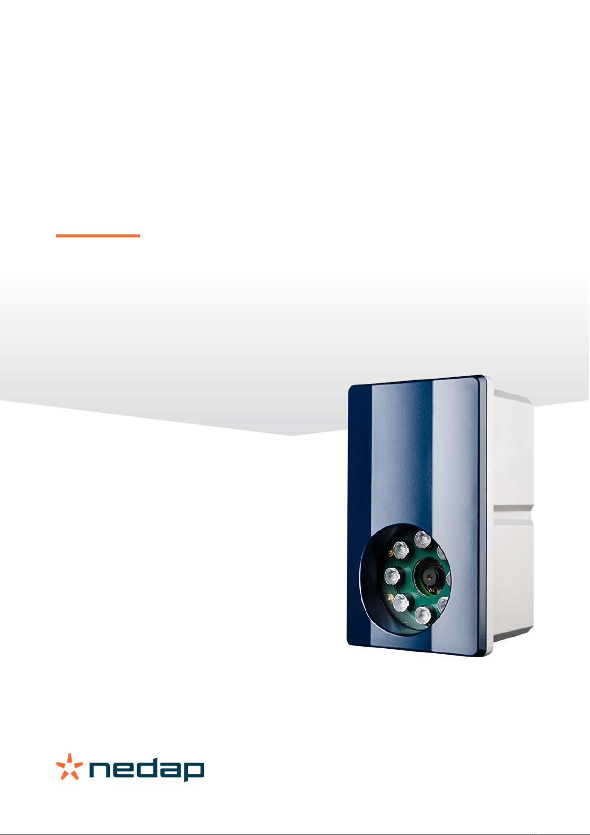
The NEDAP ANPR LUMO License Plate Reader offers automatic number plate reading. The NEDAP ANPR LUMO is an all
in one camera including camera, analyzer and IR illuminator. The ANPR has embedded processing software onboard.
The License Plate Reader is default featured with RS485, Wiegand and Ethernet communication.
1.1 Typical applications
Typical applications include parking, crime prevention, toll systems, security and access control, logistics and customs.
In addition the NEDAP ANPR LUMO can be applied in applications where it is difficult to issue RFID tags.
1.2 Key features
•Automatic number plate reading.
•All-in-one system including camera, analyzer, IR illuminator.
•ANPR LUMO optimal performance in range from 2 to 10 meters.
•Easy user configuration (web server).
•TCP/IP Ethernet interface.
•RS485 serial interface.
•OSDP v2 supported including secure channel protocol.
•Wiegand 26 bit/64 bit.
•Wiegand match-list with custom Wiegand format.
•Digital inputs.
•Stand-alone operation supported by digital outputs and black-, white-, ignore list features.
•Advanced access lists features through regular expressions.
•Multiple regions of interest
•Power over Ethernet
•REST API

ANPR LUMO | installation guide
6/
39
2Getting started
2.1 Mounting the ANPR LUMO
Determine how to mount the ANPR. The ANPR LUMO can be installed onto a pole or behind the barrier. Mount behind
the barrier to ensure recognition right in front of the barrier.
Important mounting issues are:
•Best focus distance is between 2 and 10 meters [7 … 26 ft].
•Angle between ANPR and number plate should be smaller than 25 degrees.
Mounting details are described in chapter 3.2.
2.2 Connecting the ANPR
The ANPR is delivered with 5m cables for power, I/O and network. Power supply, RS485 communication and I/O are
combined in one cable. Ethernet network is a separate cable. The cables are pre-fitted to the ANPR. For installation the
ANPR does not need to be opened. Connecting the power supply and network cable are required to configure the
ANPR.
2.3 Assigning an IP-address
Enter the default IP-address in the address bar of your web browser.
Default IP address is:
IP address: 192.168.3.15
The login window appears where the user is asked to type the username and password.
Username: admin
Password: secret
Go to the system configuration and setup the network configuration as desired. If required, now also other
configuration settings may be changed.
Note : The ANPR LUMO software interface is not compatible with Internet explorer
2.4 Testing the ANPR
Test the ANPR to check if it is aligned correctly and if it is able to read the license plates. Drive the vehicle into the
position where it should be possible to read its license plate.
Connect to the ANPR using your web browser on the main page you can see the live video. On the right side of the page
the text results are shown. It might be necessary to adjust the ANPR alignment.

ANPR LUMO | installation guide
7/
39
3Installation
3.1 Safety precautions
The following safety precautions must be observed during normal use, service and repair.
•The ANPR shall be connected to safety ground.
•Disconnect the power supply before removing any parts.
•The ANPR shall only be installed and serviced by qualified and trained personnel.
•To be sure of safety, do not modify or add anything other than mentioned in this manual or indicated by NEDAP
N.V.
•CAUTION: for continued protection against risk of fire, replace fuses only with the same type and rating.
•The ANPR can be powered from a low power, Class 2 power supply, in compliance with local regulations or
through POE.
•The product is to be connected only to PoE networks without routing to the outside plant.
•The ANPR is equipped with an 850nm Infrared illuminator. The human eye will not or slightly see this light
coming from the illuminator. Do not look into the ANPR lens directly from close range or for more than 100
seconds. Eyes can be damaged by not taking these precautions. During normal use of the ANPR at a vehicle
gate, reading plates, there is no risk to the public.
3.2 Mounting
The ANPR is intended for vehicle access control. Vehicles are identified by the number plate when approaching the
gate. Because the number plate recognition is very fast, a full stop is normally not necessary. The ANPR covers a
reading distance of 2 to 8 meters. The field of view is typically one lane wide. There are 2 recommended positions for
the ANPR.
3.2.1 Pole mounting
The ANPR is positioned directly behind or in front of the actual barrier onto a pole. In that case the ANPR can be best
positioned on a pole at maximum 2m20 height. In this position the number plate of the vehicle directly in front of the
barrier cannot be read anymore. So these vehicles need to be recognized in flow. Mounting the ANPR at 2m20 height is
here the best option. When overhead installation is an option, the ANPR can at best be installed in the center of the
lane, above the lane. Horizontal angle will be 0° in that case, which is good.
Figure 1: Pole mounting (ANPR LUMO)

ANPR LUMO | installation guide
8/
39
3.2.2 Behind barrier mounting
The ANPR is positioned behind the barrier at bumper height.
If there is space behind the barrier and the sight is not blocked, then the best place for the ANPR is at bumper height
(0.5m height) about 2 to 3 meters behind the barrier. A vehicle just in front of the barrier is still recognized in that case.
Figure 2: Behind the barrier mounting (ANPR LUMO)
3.3 Dimensions
Figure 3: ANPR housing dimensions
76.5
104
104
M6 (4x)
76.5
M4x12 (6x)
35
91
118

ANPR LUMO | installation guide
9/
39
Figure 4: Mounting bracket dimensions
104
83
66
34
Ø7 (4x)
65
80
60° max
60° max

ANPR LUMO | installation guide
10/
39
4Connections
The ANPR is delivered with two 5m long cables. Power supply, RS485 communication and I/O are combined in one cable.
Ethernet network is a second cable. The cables are pre-fitted to the ANPR. For installation the ANPR does not need to be
opened.
4.1 Ethernet connection
The Ethernet cable is already fitted to the ANPR provided an RJ-45 connector. This Cat5e cable will be adequate for
connection of the unit to a local area network. The ANPR LUMO can also be powered through Power Over Ethernet
(POE).
4.2 Power supply
RED Power supply +24VDC ~ 1A
BLUE Ground 0V
BLACK Ground 0V
Note: the ANPR LUMO may also be powered through POE
4.3 RS485 connection
YELLOW RS-485 A
GREEN RS-485 B
PURPLE RS-485 GND
4.4 Wiegand connection
WHITE Wiegand Data-0
BROWN Wiegand Data-1
PURPLE Wiegand GND
4.5 Digital I/O
PINK Digital input IN 1 + (optocoupler positive contact, U = 5 - 24VDC)
GRAY Digital input IN 1 -
GRAY/PINK Digital input IN 2 + (optocoupler positive contact, U = 5 - 24VDC)
RED/BLUE Digital input IN 2 -
WHITE/GREEN Relay output 1 (normally open contact, Umax = 24VDC, Imax = 2A).
BROWN/GREEN Relay output 1 (common contact).
WHITE/YELLOW Relay output 2 (normally open contact, Umax = 24VDC, Imax = 2A).
BROWN/YELLOW Relay output 2 (common contact).

ANPR LUMO | installation guide
11/
39
5OSDP
The ANPR LUMO support OSDP v2 , including the secure channel protocol.
5.1 Requirements
ANPR LUMO (art.no. 9986138) hardware revision A.05.
ANPR LUMO software v4.5.1 (or newer).
5.2 Connections
The OSDP communication is performed on the RS485 interface. See chapter 4.3 for a description of the RS485
connections. The communication can be connected in point-to-point or in multi-drop.
5.3 Configuration
Enable the OSDP communication in SYSTEM SETTINGS - SERIAL SETUP. See page 37.
Here you also set the OSDP baudrate, the OSDP device address and the secure protocol encryption key (SCBK).
5.4 Plate reading messages
Ensure that you enable a SERIAL-OSDP action upon a READ-event. See page 32.
The ANPR LUMO will send an OSDP_RAW message including the message data. The data report will be sent in response
to a poll command (OSDP_POLL).
OSDP_RAW message format:
CMD OSDP_RAW (fixed value 0x50)
byte 0 Reader number (fixed value 0x00)
byte 1 Format code (fixed value 0x00 = raw bit array)
byte 2/3 Bit count data length LSB first (bit count = length in bytes x 8)
byte 4/N Message data
Example license plate = "HK55EVB" :
50 00 00 38 00 48 4B 35 35 45 56 42
48 4B 35 35 45 56 42 = "HK55EVB"
38 00 = Bit count 56 (56/8 = 7 bytes)
5.5 Relay outputs
Use the OSDP_OUT command to control the relay outputs.
Output #0 = Relay 1.
Output #1 = Relay 2.
See chapter 4.5 for a description of the digital IO connections.

ANPR LUMO | installation guide
12/
39
5.6 Digital inputs
Upon status change the ANPR LUMO will send input status report message OSDP_ISTATR.
The current input status can be requested by sending the input status report request message OSDP_ISTAT.
Input #0 = Digital input 1.
Input #1 = Digital input 2.
See chapter 4.5 for a description of the digital IO connections.
5.7 OSDP capabilities
The ANPR LUMO supports the OSDP v2 including the secure channel protocol.
The OSDP control panel (CP) can request the device capabilities using the OSDP_CAP command. The ANPR LUMO will
respond with the OSDP_PDCAP device capabilities report. Below an overview of the ANPR device capabilities.
Function code
ANPR LUMO
1
Input
2x IN (no supervision)
2
Output
2x OUT (+timed)
3
Card data format
Raw array of bits
4
LED control
No user LED
5
Buzzer control
No buzzer
6
Text output
No display
7
Time keeping
The ANPR LUMO is able to locally update the time and date.
8
Check character report
CRC
9
Communication security
Yes, encrypted AES128
10
Receive buffer size
65535 bytes

ANPR LUMO | installation guide
13/
39
6Configuration
6.1 Using the web server
Prior to accessing the ANPR using a Browser, make sure the PC network configuration is coherent with the IP-address
of the device to access. E.g.: if the ANPR IP-address is 192.168.3.15, the PC in use should have assigned an IP-address
belonging to the same class (e.g. 192.168.3.10). See also chapter 8.1.1 for details about how to assign an IP-address
to the ANPR.
Figure 5: Using the web server
Enter the IP-address in the address bar of your web browser.
The login window appears where the user is asked to type the username and password.
Factory default username and password are:
Username: admin
Password: secret
If the login was successful, the user is now able to access the main menu screen.
Note: This document will describe all function available in ANPR LUMO version 4.3.2

ANPR LUMO | installation guide
14/
39
6.2 Menu Items
6.2.1 Home
The Home screen has 3 items, the live view, the Live text results and the camera information. At the camera info box,
you can check which version of the software is currently installed in the camera.
The Yellow box within the LIVE VIEW represents the region of interest, this region of interest can be changed in the
configuration menu, see chapter 7.2.

ANPR LUMO | installation guide
15/
39
6.2.2 Text results
There are three different events that the results are listed for: Accepted Results, Wrong Direction Results and
NoRead Log.
At the ACCEPTED RESULTS tab you can see all past results, the text results can be exported to a CSV file or excel file.
The images can also be exported, when pressing the “EXPORT IMAGES” button, a zip file will be created containing the
images. (depending on the amount of images, creating the zipfile can take a while)
The history is limited to the settings made at “HISTORY HOURS” and “HISTORY LIST LENGTH”.
Below the image of the actual read you can find more detailed information. The details are in which area the plate is
matched, if the plate was on one of the access lists, and what action where performed.
WRONG DIRECTION RESULTS tab lists all the plates that were detected, but were outside of the designated area and
moving in the wrong direction.
NoRead Log tab logs all the NoRead events since the server started.
Note
By default the historical length and hours is set to zero.
When changing these values follow the local privacy regulations

ANPR LUMO | installation guide
16/
39
6.3 Access list
The ANPR LUMO has three “Access” lists, and one Wiegand Matchlist. The “access” lists can be used to trigger an
action like activating a relay. These actions can be defined in the menu “configuration” -> “Actions” see chapter 7.3.
There are two ways to add plates to a list, you can either import a list, or manually add a plate to the list.
In the image below the license plate “80XHZ7” is always enabled, meaning that this plate is valid on this list forever.
In the example below, the plate is only valid on Monday, Tuesday, Wednesday, Thursday and Friday, in the period from
7-1-2018 until 25-2-2018 from 00:00 until 23:59

ANPR LUMO | installation guide
17/
39
When you want to upload a file through the “IMPORT” button, follow these directives:
Open any text editor to create a file and save it any_name.txt. Only textual documents can be imported.
Enter the information according to the formatting rules and save the file. On the ACCESS configuration page click
on ,Import’ and select the newly created document from your device.
If importing was successful the content from the document will display on the screen. This list can here be edited if
needed.
Note
A regular expression beginning with a * is invalid, because the * operator does not proceed any other
atom! Use .* instead!
Formatting rules:
•Do not use blank spaces, everything should be written in a single line.
•Plate number, date and time must be separated with semicolons (;).
•When listing multiple dates/times separate them with a comma (,).
•Date format is: YYYYMMDD-YYYYMMDD, with no space between the numbers.
•Time format is: HH:MM-HH:MM. Time is always defined in combination with a date and a symbol (0/1) for the
referred day of the week.
•Days of the week are represented with zeros and ones (0-not active, 1-active) written inside brackets starting
with Sunday, ending with Saturday (0111110). In example "0111110" non-active days are Sunday and
Saturday, represented with zeros (0).
•The amount of dates set must be equal to the amount of time restrictions ( W223344;20170101-
20170101,20170102-20170102,20170103-20170103;03:00-04:00(0111110),03:00-
04:00(0111110),03:00-04:00(0111110) ). If there are more dates than time restrictions (and vice versa) the
command will be perceived as invalid.
Example
Description
Only plate number
W223344
Always enabled
Plate number and date
W223344;20190125-20190226
Valid from 25 January 2019 until 26 February 2019
Plate number, date and
time
W223344;20190125-20190225;03:00-
17:00(0111110)
Valid from 25 January 2019 until 26 February 2019,
between 03:00 and 17:00 on every day of the week
except Saturday and Sunday (0111110)

ANPR LUMO | installation guide
18/
39
Regular Expressions
Regular expressions are used to conveniently define patterns for license plates or groups of license plate strings.
The ANPR LUMO uses a powerful set of regular expressions, of which the most important details are described in the
following paragraphs.
In the ANPR LUMO regular expressions, all characters match themselves (example: A is always A, B matches B etc.)
except for some special characters:
.[] {} *+?
The single character '.' when used outside of a character set (see below) will match any single character. E.g. the
regular expression G.23456 will match G123456, or GU23456
(In the above expression, the "." is matched by 1 or U respectively)
A character range is defined by a list of characters enclosed in []. For example [A-D] will match any single character in
the range 'A' to 'D'. This character range may also be defined as [ABCD].
An atom is defined as being a character or character range.
A single atom can be repeated with the * , +, ?, and {} operators.
The * operator will match the preceding atom zero or more times, for example the expression A*B will match any of the
following: B AB AAAAAAAAAB or the expression A[BC]*D will match AD ABCD ACCCBBD
The + operator will match the preceding atom one or more times, for example the expression A+B will match any of the
following: AB AAAAAAAAB But will not match: B
The ? operator will match the preceding atom zero or one time, for example the expression CA?B will match any of the
following: CB CAB But will not match: CAAB
An atom can also be repeated with a bounded repeat, where the number of allowed repeats is defined as part of the
regular expression:
A{n} Matches 'A' repeated exactly n times.
A{n,} Matches 'A' repeated n or more times.
A{n, m} Matches 'A' repeated between n and m times inclusive.
For example:
A{2,3}
Will match either of: AA AAA But neither of: A AAAA
The following paragraphs give some examples for regular expressions and use cases:
To match any license plate strings of at least length 1:
.+
Match license plate strings which consist of digits only:
[0-9]+

ANPR LUMO | installation guide
19/
39
Match all taxis, under the assumption that taxis have a license plate string that ends with TX:
.+TX
Match all license plates that start with a letter and end with a digit:
[A-Z]+.*[0-9]+
Match all license plates from the Nedap company, assuming that their license plates consist of a NEDAP string and a
following 3 number digit (like NEDAP001):
NEDAP[0-9]{3}
When making a list using regular expressions, the string should always start with "!" sign.
6.3.1 Wiegand matchlist
The Wiegand matchlist makes it possible to match a license plate with a pre-defined Wiegand ID.
In the example below the license plate “21ZGNL” is matched with Wiegand ID 12, the license plate 30XHZ2 is matched
with Wiegand ID 17.
A number plate which is not on the list, will be send as 1112
The Wiegand output format must be defined in the ACTIONS menu. See chapter 7.3.

ANPR LUMO | installation guide
20/
39
7Configuration menus
7.1 CAMERA
After installation camera configuration should take place. The essential segment of ANPR is image acquisition. Quality of
images depends on the camera and illumination preferences.
The area within the green polygon is the brightness control region of interest (ROI). It defines the image area within
which the camera measures and corrects the image brightness. With the “SYNC” button you can synchronize the
Region of interest settings from the ANPR menu.
It is important to minimize this surface and limit it to the area only where plates are expected to appear. This
maximizes the impacted of brightness control parameters during image acquisition, on the selected area. You have to
press the “APPLY” button.
Explanation CAMERA SETTINGS:
MIMIMUM GAIN (DB):Gain controls the amplification of the signal from the cameras sensor. It boosts the
signal by some amount thereby making already captured images look brighter. As a
result of signal enhancement negative image blur may occur. Default 0
MAXIMUM GAIN (DB): Gain controls the amplification of the signal from the cameras sensor. It boosts the
signal by some amount thereby making already captured images look brighter.
As a result of signal enhancement negative image blur may occur. The reason is
that the overall signal is boosted, making also noise more visible.
Reasonable upper limits are typically 6-10 db. We recommend a maximum gain
value of 10 for the Camera. Default 10
MINIMUM SHUTTER (µs): Minimum shutter refers to minimal exposure time in microseconds that the shutter will stay
open. Default 1
Other manuals for ANPR LUMO
2
Table of contents
Other Nedap Wireless Access Point manuals


