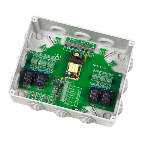
Neets 4 Relay box User manual


Page 1 Doc no#: 306-0003-002 REV400 Neets 4 relay
Foreword:
The purpose of this document is to describe how to install and configure Neets 2 relay box
COPYRIGHT - All information contained in this manual is the intellectual property of and copyrighted
material of Neets. All rights are reserved. You may not allow any third party access to content, information
or data in this manual without Neets’ express written consent.
CHANGES - Neets reserve the right to change the specification and functions of this product without any
notice.
Questions, AFTER reading this manual, can be addressed to your local dealer or:
Neets
Langballe 4
8700 Horsens
Denmark
or you may use our contact form at www.neets.dk
Revision list:
Author: Date
Description
Pages
SDV 28-09-09
New design
All
DB 09-03-12
New company address
1

Doc no#: 306-0003-002 REV400 Neets 4 relay Page 2
Index
Foreword: .......................................................................................................................................................... 1
Revision list:....................................................................................................................................................... 1
Index .................................................................................................................................................................. 2
Description ........................................................................................................................................................ 3
Technical specification ...................................................................................................................................... 5
Accessories ........................................................................................................................................................ 5
How to connect it? ............................................................................................................................................ 6
Connecting the Relay box to the control system. ......................................................................................... 6
Relaybox in screen high security mode. ........................................................................................................ 8
How to connect more than 2 relay boxes to one RS-232 Line ...................................................................... 8
Change the ID number of the relay box. ........................................................................................................... 9
RS-232 protocol ............................................................................................................................................... 10
Commands................................................................................................................................................... 10
Controlling the relays .................................................................................................................................. 11
Linking two relays together......................................................................................................................... 12
Example ........................................................................................................................................................... 13
Adding additional security........................................................................................................................... 15

Page 3 Doc no#: 306-0003-002 REV400 Neets 4 relay
Description
The Neets 4 Relay box gives you 4 dry contact relays that each can be controlled by a
control input1(Supported by all Neets Control systems) or by RS-232.
On each of the four relays you have access to both the NO (Normal open contacts) and
the NC (Normal close contacts). This gives you the opportunity to use it according to your
needs.
When using the Neets 4 relay box you have the benefit of selecting what type of voltage you want at
installation time.
The flexibility of the relay box offers you the possibility to control both high voltage and low voltage
application in the same relay box.
When 4 relays are not enough
The Neets relay box gives you the possibility to connect up to 4 boxes together on the same RS-232. When
doing this you get up to 16 relays that are all controllable individually by only one RS-232 port.
All Neets control systems support up to 2 relay boxes on one RS-232 port as it is. If you want more than 2
relay boxes on a RS-232 port, you have to use an active splitter and connect it as shown on page 8.
Safe way to control a screen or lift
The relay box, offers you the possibility to link two relays together and thereby adding extra security when
controlling e.g. screen or projector lift.
When two relays are linked together only one of the relay can be “Set” at a time.
Furthermore, you can define the time from one of the linked relays is “Released” to it is possible to “Set” a
relay again, this time adds additional protection of the connected screen/lift motor.
When using this security feature, it is active whether you control the relay box by the 4 control inputs or by
RS-232.
1“Control inputs” is the name used in this manual for the 4 inputs that allows the Neets control system to
control it directly.
Com
NCNO

Doc no#: 306-0003-002 REV400 Neets 4 relay Page 4
Relay
connectors.
LED for indication
of the relay state
Test buttons for
manual activation
of a relay
Control and
power connector.

Page 5 Doc no#: 306-0003-002 REV400 Neets 4 relay
Technical specification
Technical details:
Power supply (Not included) 9 V Dc/300mA
Relay load max AC1: 1150 Watt
Relay load max AC15 (230VAC): 500 Watt
Relay Single-phase motor rating (230 VAC): 370 Watt
Relay max voltage: 230 VAC
Control inputs: Active when connected to ground.
RS-232 communication: 9600 baud rate, 8 bit, 1 stop, none parity
Accessories
Order
number
Description
Image
306-0005
2 protections caps. When using High voltage
the protection cap protects you from high
voltage. The cap gives the wires relief and it
makes it easy to detach connectors from the
relay box.
302-0007
9 V Dc, 300mA power supply.
306-0006
Neets Serial splitter 1-4.

Doc no#: 306-0003-002 REV400 Neets 4 relay Page 6
How to connect it?
This section will cover how to connect the Neets Control –EU with the Relay box 306-0003. It will also give
some examples on how to connect an external device to the relay box, please note that there are several
other ways to use the relay box than described in this guide.
ALWAYS be sure that 230 VAC is disconnected when installing/changing ANYTHING.
Connecting the Relay box to the control system.
Pin name
Description
GND
Ground
Rx
RS-232 Receive data from control system (or PC
when testing or setting up the relay box)
GND
Ground
+9V
9 V Dc positive supply for the Relay box (Power
supply not included)
Relay 1
Control input for Relay 1. Relay is activated when
pin is GND.
Relay 2
Control input for Relay 2. Relay is activated when
pin is GND.
Relay 3
Control input for Relay 3. Relay is activated when
pin is GND.
Relay 4
Control input for Relay 4. Relay is activated when
pin is GND.
GND
Ground
If you control the relay box with both its input controls and by RS-232, you have to be aware that if the
relay is activated by RS-232, you can not release it with the input controls and vice versa.
When controlling the relay box from the Neets Control –EU system you can connect it like this:

Page 7 Doc no#: 306-0003-002 REV400 Neets 4 relay

Doc no#: 306-0003-002 REV400 Neets 4 relay Page 8
Relaybox in screen high security mode.
In the Neets Control panels there is a blocking which prevents wrong polarity when switching relays. This
can be bypassed, and therefore we recommend to connect a 230 Volt AC controlled screen like the drawing
below. This prevents any changes for making short circuit.
The Relay 1 is now controlling the screen in one direction, and there is ONLY power to the screens other
direction when Relay 1 is “Released”. Be sure to set up the software to fit this hardware configuration.
How to connect more than 2 relay boxes to one RS-232 Line
A standard RS-232 line only allows you to have two RS-232 devices attach. If you need more than two, you
have to use the Neets Serial splitter 1-4 as well. Below you can see how it can be connected.

Page 9 Doc no#: 306-0003-002 REV400 Neets 4 relay
Change the ID number of the relay box.
The relay box can be assigned an ID that allows up to 4 individual relay boxes to be connected to the same
RS-232 port.
When power is connected to the relay box the four led on the relay box will indicate the ID number of the
relay box for 3 seconds (See table below for details).
To change the ID number of the relay box you must connect power to the relay box and within 3 second
press and hold down the test button for four seconds. The test button you press must correspond to the ID
you want to assign.
Relay box ID
LED status when
power on
Test button to press
when changing to this ID
None/0
Relay 1 + 2 + 3 + 42
1
Relay 1
2
Relay 2
3
Relay 3
4
Relay 4
2This is the default settings.

Doc no#: 306-0003-002 REV400 Neets 4 relay Page 10
RS-232 protocol
It is possible to control the relay box from a control system or a computer that is equipped with a RS-232
port.
Communication condition
The serial port on the device that controls the relay box must match the following:
Description
Settings
Baud rate
9600
Data length
8 bit
Parity bit
None
Stop bit
1 bit
Flow control
None
Commands
When entering all the commands in the Neets Control Utility software, select “Chr” as input format.
To easier understand the commands below please keep this in mind.
Please be aware that all the RS-232 commands are case sensitive. If the relay box detects an error in the
command line, the entire command will be ignored.
Sending multiple commands is possible without time delay between commands. Just remember that each
command must end with \CR.
Symbol
Description
<X>
When constructing the command, this part must be replaced with a sting or number.
[ ]
The braces indicate that what is inside only have to be included in the command the
function is required.
In the command, the braces are not included.
\CR
Every command line must end with a carriage return.
Carriage return is commonly referred to as “CR” or if you need to enter et in hex the value
is 0D and in decimal it is 13.

Page 11 Doc no#: 306-0003-002 REV400 Neets 4 relay
To do this in the Neets Configurations Utility please look below:
We want to send two commands: Relay=1,Action=Set\CR and Relay=2,Action=Release\CR
Controlling the relays
The RS-232 commands gives you fully control over all the relays.
You can do simple things like “Set”, “Release” or “Toggle” the state of a relay.
More advance functions like “Delay” and “Time” is also supported.
Command:Relay=<Y>,Action=<X>[,Delay=<W>][,Time=<Q>][,Unit=<Z>]\CR
Below you find some examples on how to control the relays.
1. Activate relay 2 on all relay boxes connected.
Relay=<Y>
Description
1-4
Set the number of the relay that you want to control.
Action=<X>
Description
Set
Set the relay
Release
Release the relay
Toggle
Toggle the relay. (if the relay is “Set” it will be “Released” and vice versa)
Delay=<W>
Description
0-6553.5
Set the time (in seconds) from the command is send to the action is executed.
The minimum step is 100 ms.
Time=<Q>
Description
0-6553.5
Set the time (in seconds) from the action is executed to the relay returns to its
original state. The minimum step is 100 ms.
Unit=<Z>
Description
0-4
Set the ID number of the relay box this command is intended to. If Unit number is
0 or not used the message will be send to all relay boxes.
This character has been entered by changing to
input format “Hex” and type in the value ”0D”
and then change bach to input format “Chr”.

Doc no#: 306-0003-002 REV400 Neets 4 relay Page 12
Relay=2,Action=Set\CR
When entering this command in the Neets Configurations Utility its looks like this:
2. Activate relay 3 for 20 seconds on relay box with ID unit 2.
Relay=3,Action=Set,Time=20,Unit=2\CR
3. Toggle relay 4, 12 seconds after the command is send and then hold it for 5,8 seconds.
Relay=4,Action=Toggle,Delay=12,Time=5.8,Unit=2\CR
Linking two relays together
As mention earlier, it is possible to link two relays together. Two linked relays are not able to be “Set” at
the same time and further more it is possible to define the time from one relay is released to the next can
be “Set”.
Command:Group=<G>,Action=<X>[,Delay=<W>][,Unit=<Z>]\CR
Below you find some examples on how to link and unlink relays together:
1. Link relay 1 and 2 together on all relay boxes connected.
Group=1,Action=Lock\CR
Group=<G>
Description
1
Relay 1 and 2
2
Relay 3 and 4
Action=<X>
Description
Lock
Lock the selected group.
Unlock
Unlock the selected group. The relay in the group is no longer linked.
Delay=<W>
Description
0-25.5
Set the time (in seconds) from one relay is released to the next in the group can
be “Set”. The minimum step is 100 ms.
Unit=<W>
Description
0-4
Set the ID number of the relay box this command is intended to. If Unit number is
0 or not used the message will be send to all relay boxes.

Page 13 Doc no#: 306-0003-002 REV400 Neets 4 relay
2. Link relay 3 and 4 together and set the safety delay to 3,6 seconds on all units connected.
Group=2,Action=Lock,Delay=3.6\CR
3. Unlink relay 1 and 2 on the relay box with ID number 3.
Group=1,Action=Unlock,Unit=3\CR
Example
In this section, you can read how an installation with projector, electrical screen, and electrical lift can be
done.
On the hardware side, we need:
1 projector
1 Neets Control - EU Professional or Neets Control - DK
1 Neets 4 relay box
Below you find the wiring diagram that shows the communication lines.
The relays now have the following functions.

Doc no#: 306-0003-002 REV400 Neets 4 relay Page 14
Relay
Function
Relay 1
Screen up (It takes 26 sec to move the screen up)
Relay 2
Screen down (It takes 20 sec to move the screen down)
Relay 3
Lift up (It takes 22 sec to move lift up)
Relay 4
Lift down (It takes 22 sec to move lift down)
Then application must be able to control the system:
When the projector is turned on the lift and screen must move to the “down” position.
When the projector is turned off the lift and screen must move to the “up” position.
There must be a manual control for the screen.
Command to be used when turning on the projector:
Relay=1,Action=Release\CR
Relay=2,Action=Set,Time=20\CR
Relay=3,Action=Release\CR
Relay=4,Action=Set,Time=22\CR
Command to be used when turning off the projector:
Relay=2,Action=Release\CR
Relay=1,Action=Set,Time=26\CR
Relay=4,Action=Release\CR
Relay=3,Action=Set,Time=22\CR
Command to be used when manual moving the screen down:
Relay=1,Action=Release\CR
Relay=2,Action=Set,Time=20\CR
Command to be used when manual moving the screen up:
Relay=2,Action=Release\CR

Page 15 Doc no#: 306-0003-002 REV400 Neets 4 relay
Relay=3,Action=Set,Time=26\CR
Adding additional security
The system we have designed now is working and with the screen and lift wired up in high security mode,
there are no chances for shortening the motors.
Many motors specifies that a certain time is required from power is disconnected from one direction to
power is connected in the other direction.
By grouping the relays that controls the screen and lift, it is possible to define the time that must elapse
from one relay is “Released” to the next is “Set”.
Device
Minimum time for changing
from one direction to
another
Screen
1,0 seconds
Lift
2,5 seconds
The commands the must be used to achieve this function is:
Group=1,Action=Lock\CR
Group=2,Action=Lock,Delay=2.5\CR
It is only necessary to send the two commands one time, the settings will be stored in the relay box, also
after power has been removed.
Other manuals for 4 Relay box
1
Table of contents
Other Neets Relay manuals
Popular Relay manuals by other brands

MÜLLER + ZIEGLER
MÜLLER + ZIEGLER GMA-2 quick start guide
IDEC
IDEC LD6A Series instruction sheet
Allen-Bradley
Allen-Bradley MINOTAUR MSR144RTP manual
Eaton
Eaton Digitrip 3000 series Installation, operation and maintenance instructions

Moeller
Moeller ZB12 Series Hardware and engineering
Revo
Revo S2PH user manual
