manuals.online logo
Brands
  1. Home
  2. •
  3. Brands
  4. •
  5. Zander Aachen
  6. •
  7. Relay
  8. •
  9. Zander Aachen SR7D User manual

Zander Aachen SR7D User manual

User Manual
1
Safety Coupling Relay SR7D
M03
Ver. A
E61-358-00
H. ZANDER GmbH & Co. KG • Am Gut Wolf 15 • 52070 Aache • Germa y
Tel +49 241 9105010 • Fax +49 241 91050138 • info@zander-aachen.de • www.zander-aachen.de
Safety
Precautions
•
Cyclical monitoring of the output contacts
•
LED indicators for power and status channel 1 and 2
•
2 start modes:
- monitored manual start
- automatic start
•
Short-circuit monitoring and earth fault monitoring
•
Up to PL e, SILCL 3, category 4
•
Stop category: 0
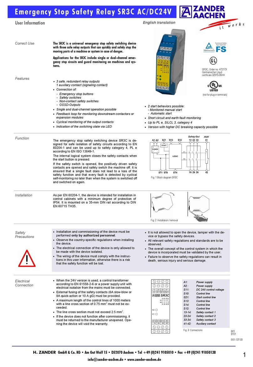
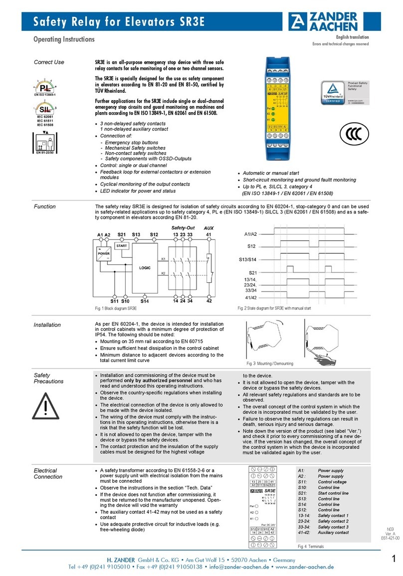
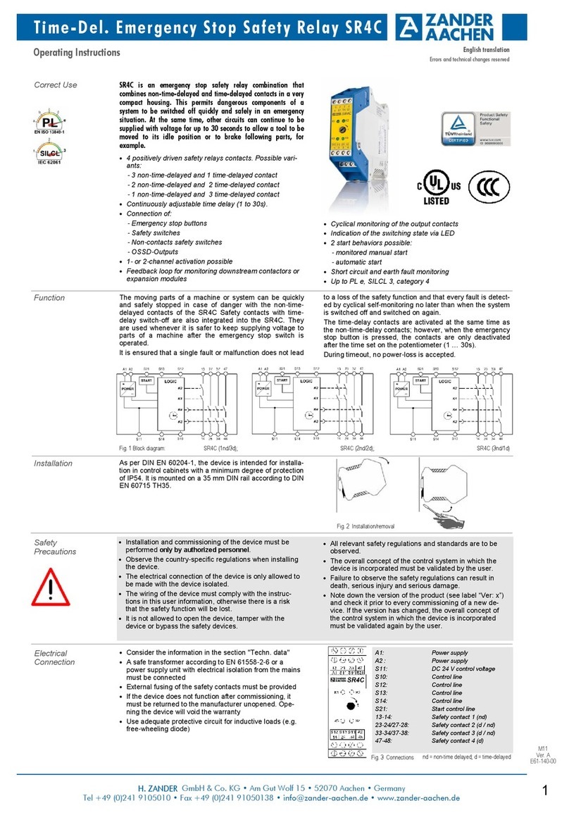
Correct Use SR7D is a safety coupling relay/safety switchgear with seven safe
relay contacts for fast and safe shutdown of hazardous plant
components in the event of danger. t can be used in particular
for furnaces and thermal process plants.
The device can be operated as a coupling relay for connection to
safe semiconductor outputs (e.g. output of a safety PLC). Due to
the integrated self-monitoring, no feedback loop is required for
error monitoring.
The SR7D is specially designed and certified for the use on
furnaces and thermal process plants in continuous operation
according to EN 50156-1 and EN 746-2.
•
7 safety contacts
•
4 auxiliary contacts (relay); 2 solid-state auxiliary outputs
•
Connection of sensors for:
•
- temperature
- pressure
- volume flow
•
Control: single or dual channel
•
Can be used as emergency stop relay with separate
safety circuit
•
Feedback loop for external contactors or extension
modules
Function
The emergency stop safety switching device SR7D is
designed for safe isolation of safety circuits according to
EN 60204-1 and can be used up to SIL 3 according to IEC
61508 and safety category 4, PL e according to EN ISO
13849-1.
When the control signal is switched on or off, the safety
contacts are closed or opened by the internal logic of the
SR7D. The SR7D can also be used as a classic emer-
gency-stop relay by appropriate wiring. In this case, the
safety contacts are closed by closing the emergency stop
circuit and a proper start command. Opening the emer-
gency stop circuit immediately opens the safety contacts.
It is ensured that a single fault does not lead to a loss of
the safety function and that every fault is detected by cycli-
cal self-monitoring no later than when the system is
Installation
As per EN 60204-1, the device is intended for installation in
control cabinets with a minimum degree of protection of
IP54. It is mounted on a 35 mm mounting rail according to
EN 60715 TH35.
The load curves (see page 4) specify the maximum permis-
sible total thermal current as a function of the ambient
temperature.
Fig. 2 Mounting / Demounting
Electrical
Connection
•
A safety transformer according to EN 61558-2-6 or a
power supply unit with electrical isolation from the mains
must be connected
•
Observe the instructions in the section “Tech. Data”
•
Use adequate protective circuit for inductive loads (e.g.
free-wheeling diode)
•
If the device does not function after commissioning, it
must be returned to the manufacturer unopened. Open-
ing the device will void the warranty
•
The auxiliary outputs 81-82, 91-92, 101-102, 101-112
and O1, O2 may not be used as safety contacts
Fig. 3 Terminals
•
It is not allowed to open the device, tamper with the de-
vice or bypass the safety devices.
•
All relevant safety regulations and standards are to be
observed.
•
The overall concept of the control system in which the
device is incorporated must be validated by the user.
•
Failure to observe the safety regulations can result in
death, serious injury and serious damage.
•
Note down the version of the product (see label “Ver.”)
and check it prior to every commissioning of a new de-
vice. If the version has changed, the overall concept of
the control system in which the device is incorporated
must be validated again by the user.
•
Installation and commissioning of the device must be
performed only by authorized personnel and who has
read and understood this operating instructions.
•
Observe the country-specific regulations when installing
the device.
•
The electrical connection of the device is only allowed to
be made with the device isolated.
•
The wiring of the device must comply with the instruc-
tions in this operating instructions, otherwise there is a
risk that the safety function will be lost.
•
The contact protection and the insulation of the supply
cables must be designed for the highest voltage to the
device.
switched off and switched on again. The operating status of
the device is signalled via the semiconductor monitoring
outputs O1 and O2 (reference potential: 0V terminal).
O1: Device ready for operation, PWR (UB) applied.
O2: Both relays K1 and K2 are switched on.
Fig. 1 Blo k diagram SR7D
A1: Power Supply
A2 : Power Supply
S11: DC 24 V control voltage
S10: Control line
S12: Control line
S13: Control line
S14: Control line
S21: Control line Start
O1;O2: Solid-state aux. outputs
0V: Ref. potential O1/O2
81-82: Auxiliary contact
91-92: Auxiliary contact
101-102: Auxiliary contact
101-112: Auxiliary contact
13-14 ..
73-74: Safety contacts 1 to 7
English Translation
Errors and technical changes reserved
Pwr: AC/DC 24V
User Manual
2
Safety Coupling Relay SR7D
M03
Ver. A
E61-358-00
H. ZANDER GmbH & Co. KG • Am Gut Wolf 15 • 52070 Aache • Germa y
Tel +49 241 9105010 • Fax +49 241 91050138 • info@zander-aachen.de • www.zander-aachen.de
Attention:
• To activate earth fault monitoring, PE must only be connected to
the power supply unit in accordance with EN 60204-1.
• It must be ensured that any switch-on pulses sent by the signal
generator (light test) do not cause the safety relay to be activated
for a short time and should therefore always be deactivated.
• For applications according to Fig. 10 and Fig. 11 it must be en-
sured that the reference potential of the signal generator and the
SR7D is the same.
Advice: Follow the guidelines in „Electrical Connection“ during the start-up.
Commissioning
Procedure
1. Input circuit:
Depending on the risk evaluation choose one of the wiring
diagrams in „Applications“ (Fig. 4 to 11).
2. Choose start mode:
Connect the start button with S11 and S21 for monitored
manual start or connect S21 with S12 directly for automatic
start (Fig. 12 or 13).
Warning:
If “Automatic start” is set, bear in mind that the safety
contacts will switch immediately after the power supply is
connected. If “Monitored manual start” is set, the start
button must be opened after wiring.
3. Feedback loop:
If external contactors or extension modules are used,
connect them according to Fig. 14 or Fig. 15.
4. Power supply:
Connect the power supply to A1 and A2 (Fig. 16 or Fig. 10
or Fig. 11).
Caution: Power must not yet be activated.
Fig. 12:
Monitored manual start.
It is monitored that the start
button has been opened before
the safety switch is closed.
(Condition:
power supply may not be inter-
rupted)
Fig. 13:
Automatic start.
Maximum allowable delay when
closing the safety switches at
S12 and S13:
S12 before S13: 300ms
S13 before S12: no limit
Warning:
Safety contacts will be activated
immediately at power-on.
Depending on the application or the result of the risk assessment according to EN ISO 13849-1, the device must be wired as
shown in Fig. 4 to Fig. 17.
Applications
Fig. 9:
Single channel emergency stop
with ground fault monitoring.
(Category 1, up to PL c / SIL 1)
Fig. 7:
Dual channel emergency stop
with ground fault monitoring.
(Category 3, up to PL d / SIL 2)
Fig. 6:
Dual channel emergency stop
with short circuit and ground fault
monitoring.
(Category 4, up to PL e / SIL 3)
Fig. 8:
Dual channel safety guard
monitoring with short circuit and
ground fault monitoring.
(Category 4, up to PL e / SIL 3)
Emergency Stop
Circuit
Start Behaviour
Fig. 5:
Two channel emergency stop
with PNP outputs / OSSD out-
puts with its own short circuit
monitoring.
(Category 4, up to PL e / SIL 3)
Fig. 14:
Feedback loop for monitored
manual start:
The feedback loop monitors
contactors or the expansion
modules .
Feedback Loop
Fig. 15:
Feedback loop for automatic
start:
The feedback loop monitors
contactors or the expansion
modules .
Power supply
and
Safety contacts
Fig. 16:
Power supply at A1 and A2.
(Power supply according to techn.
Data)
Fig. 17:
Connecting load to safety con-
tacts.
(Figure shows example.
Voltage „+V“ according to techn.
Data)
Fig. 11:
Dual channel emergency stop
without fault-detection of the
safety switch and the wires.
(Category 3, up to PL d / SIL 2)
Fig. 10:
Single channel emergency stop
without fault-detection of the
safety switch and the wires.
(Category 1, up to PL c / SIL 1)
SR7D
SR7D
SR7D
SR7D
SR7D
SR7D
SR7D
M L+
M L+
M L+
Fig. 4:
Single channel
control via safe
output “FO"
("Safe coupling
relay" application).
(Category 4, up to
PL e / SIL 3;
Condition: Safe
output “FO“ meets
PL e, SIL 3 and
wiring is done in a
protected wiring
compartment with
a minimum de-
gree of protection
of IP54).
E-Stop
E-Stop E-Stop
E-Stop
E-Stop
Safety PLC
User Manual
3
Safety Coupling Relay SR7D
M03
Ver. A
E61-358-00
H. ZANDER GmbH & Co. KG • Am Gut Wolf 15 • 52070 Aache • Germa y
Tel +49 241 9105010 • Fax +49 241 91050138 • info@zander-aachen.de • www.zander-aachen.de
Techn. Data
In compliance with EN 60204-1; EN ISO 13849-1; IEC 62061; EN 50156-1;
EN 746-2; IEC 61508 parts 1-2 and 4-7; IEC 61511-1
Operating voltage AC/DC 24 V, AC: 50-60 Hz
Allowable tolerance + 10 % / - 10 %
Power consumption U
B
= DC 24 V: ca. 5 W / U
B
= AC 24 V: ca. 9,7 VA
Control voltage at S11 DC 24 V
Current consumption of the inputs S12: < 80 mA, S13 or S14: < 120 mA, S21: < 80 mA
Test pulse suppression:
Dark test (test pulse width / pause between test pulses) ≤5 ms / ≥200 ms
Light test (test pulse width / pause between test pulses) ≤0.5 ms / ≥200 ms
ATTENTION: It mu t be en ured that light te t pul e generated
by the ignal generator do not lead to a hort activation of the
afety relay . Therefore, it i recommended that light te t pul e
are deactivated by default, provided that they are not nece ary
for the afety level to be achieved.
Safety contacts 7 NO (each with 2 redundant relay contacts)
Auxiliary outputs 4 NC (relay contacts) + 2 solid-state PNP outputs
Maximum switching voltage AC 250 V
Contact rating of safety contacts AC: 250 V, 2000 VA, 8 A for resistive load
(13-14, 23-24, 33-34, 43-44, 53-54, 63-64, 73-74) 250 V, 3 A for AC-15
6 switching cycles per minute DC: 30 V, 240 W, 8 A for resistive load
24 V, 3 A for DC-13
Maximum cumulative current: see load curves at page 4
Contact rating of auxiliary contacts AC: 250 V, 500 VA, 2 A for resistive load
(81-82, 91-92, 101-102, 101-112) DC: 30 V, 60 W, 2 A for resistive load
Minimum contact load 5 V, 10 mA
External fuses for safety contacts 10 A gG
6 A gG for applications acc. to EN 50156-1 (see chapter
10.5.5.3.4)
Solid state auxiliary outputs switching +24 V (PNP), max. 30 mA, short-circuit proof
Wire width 0.14 mm2 to 2.5 mm2
Tightening moment (min. / max.) 0.5 Nm / 0.6 Nm
Maximum switch-on delay 30 ms
Maximum delay when requesting the safety function via S11-S12 or S11-S14/S10-S13: 10 ms,
via A1/A2: 25 ms
Maximum resistance of the control lines (incl. switches / sensor) 40 Ωat nominal operating voltage (DC 24 V)
Contact material AgSnO2
Service life mech. approx. 1 x 10⁷
Rated impulse withstand voltage 2.5 kV (control voltage / contacts)
Dielectric strength 4 kV (acc. to EN 60664-1)
Rated insulation voltage 250 V
Degree of protection IP20
Temperature range -15 °C to +55 °C (Pay attention to load curve , ee page 4)
Storage temparature -15 °C to +80 °C
Max. altitude ≤2000 m (above sea level)
Degree of pollution / Overvoltage category 2 / 3 (acc. to EN 60664-1)
Weight approx. 350 g
Mounting Mounting rail acc. to EN 60715 TH35
5. Starting the device:
Switch on the operating voltage.
Warning:
If the “Automatic start” starting behaviour is set, the
safety contacts will close immediately.
If the “Monitored manual start” starting behaviour is set,
close the start button to close the safety contacts. LEDs
K1 and K2 are lit.
6. Triggering safety function:
Open the emergency stop circuit by actuating the con-
nected safety switch. The safety contacts open immedi-
ately.
7. Reactivation:
Switch the device on again as described under 5.
Device does not switch on:
•
Check the wiring by comparing it to the wiring diagrams.
•
Check the safety switch for correct function and adjust-
ment.
•
Check whether the safety inputs are activated.
•
Check whether the start button (manual start) is closed.
•
Check the operating voltage at A1 and A2.
•
Is the feedback loop closed?
What to do in
Case of a Fault?
Opening the device is not permitted and will void the warranty.
Device cannot be switched on after a safety request:
•
Emergency stop circuit was closed again.
•
Was the start button opened before closing of the emer-
gency stop circuit (manual start)?
•
Is the feedback loop closed?
If the fault still persists, perform the steps listed under
“Commissioning Procedure”. If these steps do not remedy
the fault either, return the device to the manufacturer.
User Manual
4
Safety Coupling Relay SR7D
M03
Ver. A
E61-358-00
H. ZANDER GmbH & Co. KG • Am Gut Wolf 15 • 52070 Aache • Germa y
Tel +49 241 9105010 • Fax +49 241 91050138 • info@zander-aachen.de • www.zander-aachen.de
Dimension
Drawing
Variants
Order No. 472243 SR7D, AC/DC 24 V (AC: 50-60 Hz), fixed screw terminals
Order No. 474243 SR7D, AC/DC 24 V (AC: 50-60 Hz), incl. plug-in screw terminals
Order No. 475243 SR7D, AC/DC 24 V (AC: 50-60 Hz), incl. push-in twin spring connector
Order No. 472592 EKLS4 set plug-in screw terminals
Order No. 472595 EKLZ4 set push-in twin spring connector
Order No. 472596 Spacer for a defined minimum distance between two safety relays (see load curves)
0
10
20
30
40
50
60
70
80
90
100
110
120
130
140
0 5 10 15 20 25 30 35 40 45 50 55 60
Square of the cumulative current I² [A²
Ambient temperature [°C
Distance to adjacent devices: 0 mm
0
20
40
60
80
100
120
140
160
180
200
220
240
260
280
300
0 5 10 15 20 25 30 35 40 45 50 55 60
Square of the cumulative current I² [A²
Ambient temperature [°C
Distance to adjacent devices: 10 mm
Load Curves
Fixed
terminals
Plug-in
terminals
Disclaimer and
Warranty
Failure to comply with the above conditions for proper use,
failure to follow the safety instructions or failure to carry out
any maintenance work as required will result in a dis-
claimer of liability and loss of warranty.
ATTENTION
Please be aware that it is the sole responsibility of the
operator to ensure system availability.
The SR7D is a safety switchgear according to
•
EN ISO 13849-1
•
IEC 62061
•
IEC 61508
•
EN 50156-1
•
EN 746-2
•
IEC 61511-1
which branches to the safe state when the safety function
is requested.
This means that the connected load is switched off as soon
as a request is initiated via connected sensors, or diagnos-
tic measures register a dangerous state, e.g. caused by a
component fault.
Since process applications in particular have high availabil-
ity requirements, limited availability can also have consider-
able consequences.
It is therefore recommended to stock a second unit to avoid
long downtimes in such a case.
These are recommendations of the manufacturer, the
evaluation of the importance of the system availability is
solely the responsibility of the operator.
Check and Main-
tenance
The following checks are regularly required to ensure
proper and continuous functioning:
•
Check the switch function
•
Check for signs of manipulation and safety function
bypassing
•
Check if the device is mounted and connected securely
•
Ceck for soiling
Check if the safety device is working properly, in particular:
•
Every time after initial commissioning
•
Every time after replacing a component
•
After every fault in the safety circuit
•
According to CNB/M/11.050, a request for the safety function is recommended at the following intervals:
•
Once a month for applications up to PL e with Cat. 3 or Cat. 4, or SIL CL 3 / SIL 3 with HFT = 1
•
Once per year for applications up to PL d with cat. 3, or SIL CL 2 / SIL 2 with HFT = 1
Square of the umulative urrent:
∑ I² = (I
1
)² + (I
2
)² + (I
3
)² + (I
4
)² +(I
5
)² + (I
6
)² + (I
7
)²
with (I
1
) - (I
7
): Currents in the safety onta t paths
User Manual
5
Safety Coupling Relay SR7D
M03
Ver. A
E61-358-00
H. ZANDER GmbH & Co. KG • Am Gut Wolf 15 • 52070 Aache • Germa y
Tel +49 241 9105010 • Fax +49 241 91050138 • info@zander-aachen.de • www.zander-aachen.de
Conditions: Maximum load AC-15 / DC-13
Device type A
HFT 0
SIL 3
SFF [%] 91.58
λSD [FIT] 0
λSU [FIT] 92.59
λDD [FIT] 0
λDU [FIT] 8.51
PFDavg (e.g. for T = 1 year) 3.73E-05
Safety characteristics according to EN ISO 13849-1
Safety characteristics according to IEC 61508 - High Demand
Safety characteristics according to IEC 61508 - Low Demand
Conditions: Maximum load AC-15 / DC-13
Max. duration of use [Years] 20
Proof-Test-Intervall [Years] 5
PFDAVG 1.12E-04
SIL 3
Load - AC-15 / DC-13 ≤1 A / ≤1 A ≤2A / ≤2A ≤3A / ≤3A
Max. duration of use [Years] 20 20 20
Category 4 4 4
PL e e e
PFHd [1/h] 1.2E-08 1.2E-08 1.2E-08
nop [Cycles / year] - AC-15 / DC-13 ≤50,000 / ≤350,000 ≤35,000 / ≤100,000 ≤35,000 / ≤15,000
Conditions: Days of operation/year: 365; Hours/Day: 24; Switching-Cycle/Hour: 1,7; Maximum load AC-15 / DC-13
Max. duration of use [Years] 20
Proof-Test-Intervall [Years] 20
PFH 2.4E-10
SIL 3
Safety characteristics for alternate 1oo1 structure for process industry - Low Demand
Safety
Charcteristics
Conditions: Days of operation/year: 365; Hours/Day: 24; Switching-Cycle/Hour: 1,7; Maximum load AC-15 / DC-13
Device type A
HFT 0
SIL 3
SFF [%] 99.91
λSD [FIT] 0
λSU [FIT] 185.3
λDD [FIT] 17.33
λDU [FIT] 0.17
PFH [1/h] 2.4E-10
Safety characteristics for alternate 1oo1 structure for process industry - High Demand
In order to check the correct function of the device, the following steps must be carried out
•
Trigger the safety function via the safety circuit. Check that the safety outputs (13-14; 23-24; 33-34; 43-44; 53-54; 63-64;
73-74) have been opened by triggering the safety function.
•
Now reactivate the device by closing the safety circuit again and, if configured, trigger a start command. Check that the
safety outputs (13-14; 23-24; 33-34; 43-44; 53-54; 63-64; 73-74) are closed again.
If the unit does not switch on again, the proof test has not been passed.
ATTENTION:
If the proof test is not passed, the device must be replaced. Otherwise there is a hazard of loss of functional safety.
Proof-Test

This manual suits for next models

3

Other Zander Aachen Relay manuals

Zander Aachen SR3E User manual

Zander Aachen

Zander Aachen SR3E User manual

Zander Aachen SR3D Operation manual

Zander Aachen

Zander Aachen SR3D Operation manual

Zander Aachen SR4C User manual

Zander Aachen

Zander Aachen SR4C User manual

Zander Aachen SR3D Operation manual

Zander Aachen

Zander Aachen SR3D Operation manual

Zander Aachen SR7C User manual

Zander Aachen

Zander Aachen SR7C User manual

Zander Aachen SR7C Operation manual

Zander Aachen

Zander Aachen SR7C Operation manual

Zander Aachen SR2C User manual

Zander Aachen

Zander Aachen SR2C User manual

Zander Aachen MINOS SD1E User manual

Zander Aachen

Zander Aachen MINOS SD1E User manual

Zander Aachen ZX09 Series User manual

Zander Aachen

Zander Aachen ZX09 Series User manual

Zander Aachen SPEEDY ZX8T Operation manual

Zander Aachen

Zander Aachen SPEEDY ZX8T Operation manual

Zander Aachen SR3C User manual

Zander Aachen

Zander Aachen SR3C User manual

Zander Aachen MVisio HMI Pro User manual

Zander Aachen

Zander Aachen MVisio HMI Pro User manual

Zander Aachen SR3C Operation manual

Zander Aachen

Zander Aachen SR3C Operation manual

Popular Relay manuals by other brands

ABB CKO-5 manual

ABB

ABB CKO-5 manual

resideo R8845U manual

resideo

resideo R8845U manual

Pilz PNOZ X3 operating manual

Pilz

Pilz PNOZ X3 operating manual

Siemens SIPROTEC 5 Compact manual

Siemens

Siemens SIPROTEC 5 Compact manual

Ziton A50E-2 Installation sheet

Ziton

Ziton A50E-2 Installation sheet

Multilin PROTECT 4A-120 instruction manual

Multilin

Multilin PROTECT 4A-120 instruction manual

Pilz S3UM operating instructions

Pilz

Pilz S3UM operating instructions

Touch-plate ZoneZ Universal quick start guide

Touch-plate

Touch-plate ZoneZ Universal quick start guide

MICROENER N-DIN-MSG Operation manual

MICROENER

MICROENER N-DIN-MSG Operation manual

Leviton 40A00-1 Installation instructions and user guide

Leviton

Leviton 40A00-1 Installation instructions and user guide

Delixi XJ3 user manual

Delixi

Delixi XJ3 user manual

Eaton EASY222-DN Instruction leaflet

Eaton

Eaton EASY222-DN Instruction leaflet

CD Automation REVO S IFH 2PH user manual

CD Automation

CD Automation REVO S IFH 2PH user manual

Siemens SIRIUS 8WD44.0-0EA2 Original operating instructions

Siemens

Siemens SIRIUS 8WD44.0-0EA2 Original operating instructions

Contrinex YRB-0330-242 operating instructions

Contrinex

Contrinex YRB-0330-242 operating instructions

National Instruments SC-206X Series user manual

National Instruments

National Instruments SC-206X Series user manual

ABB Relion RER615 DNP3 Communication protocol manual

ABB

ABB Relion RER615 DNP3 Communication protocol manual

Circutor CBS-4 Series quick start guide

Circutor

Circutor CBS-4 Series quick start guide

manuals.online logo
manuals.online logoBrands
  • About & Mission
  • Contact us
  • Privacy Policy
  • Terms and Conditions

Copyright 2025 Manuals.Online. All Rights Reserved.