NEFF K7791X0 User manual

en Installation Instructions
9000 291 220 (8707)
K7791X0..

2
Content
Important Information ........................................... 3
Installation Possibilities ........................................ 3
Stand alone appliance ............................................ 3
Stand alone appliance with dividing wall ................. 3
As an end section to a row of kitchen units ............. 3
Installing the appliance ........................................ 4
Installation location ................................................. 4
Atmosphere grades ................................................ 4
Installation niche ..................................................... 4
Neighbouring kitchen furniture ................................ 4
Subsurface ............................................................. 4
Electrical connection ............................................ 5
Water Connection ................................................. 5
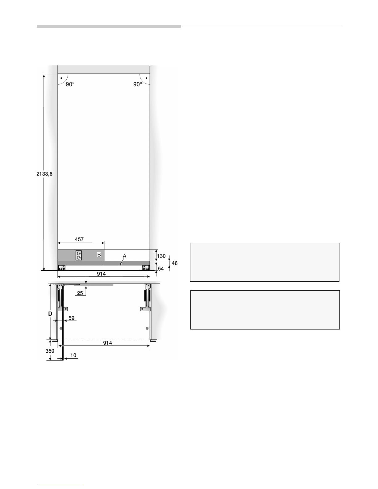
Dimensions of the Installation Niche ................... 6
Setting-up as an stand alone appliance .................. 6
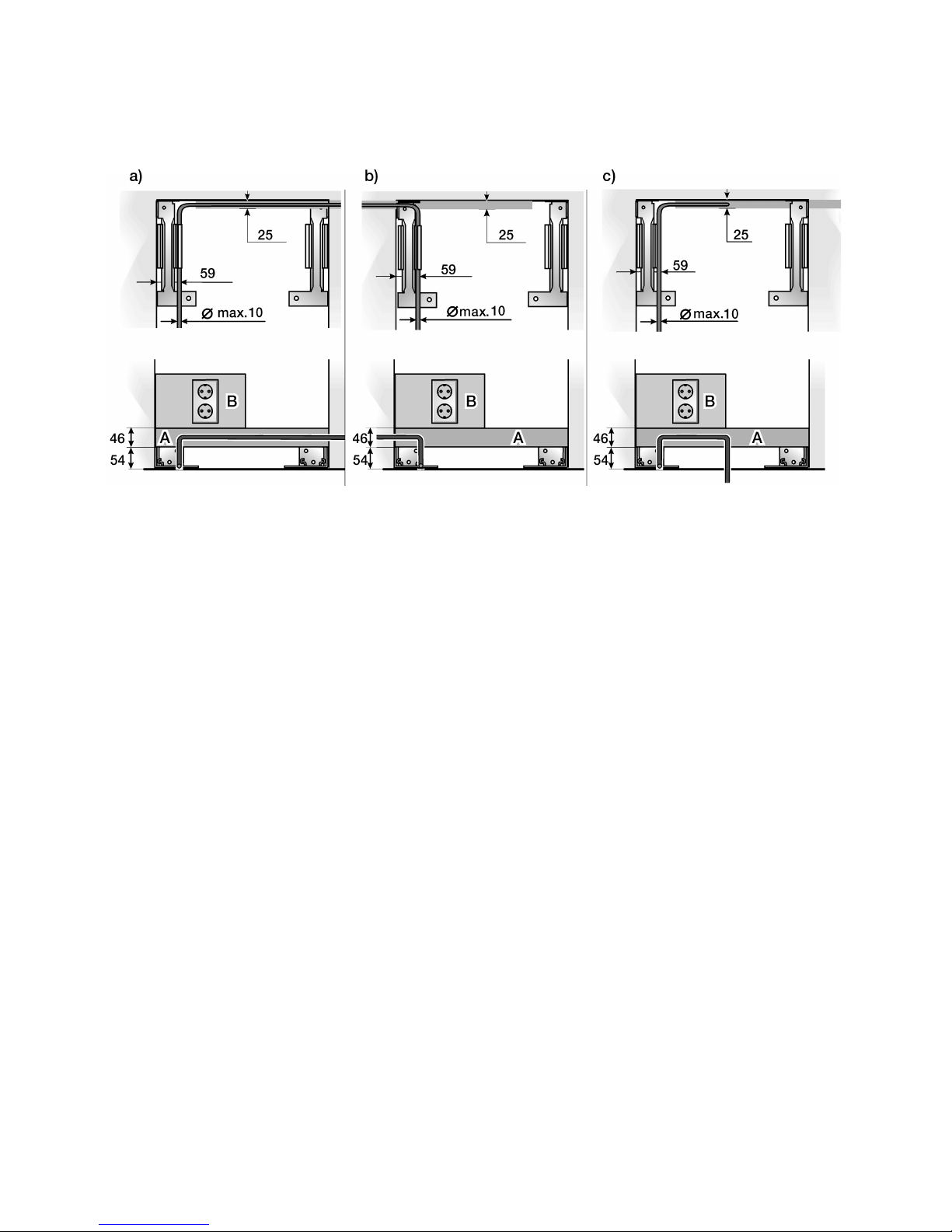
Site of the water connection ................................... 7
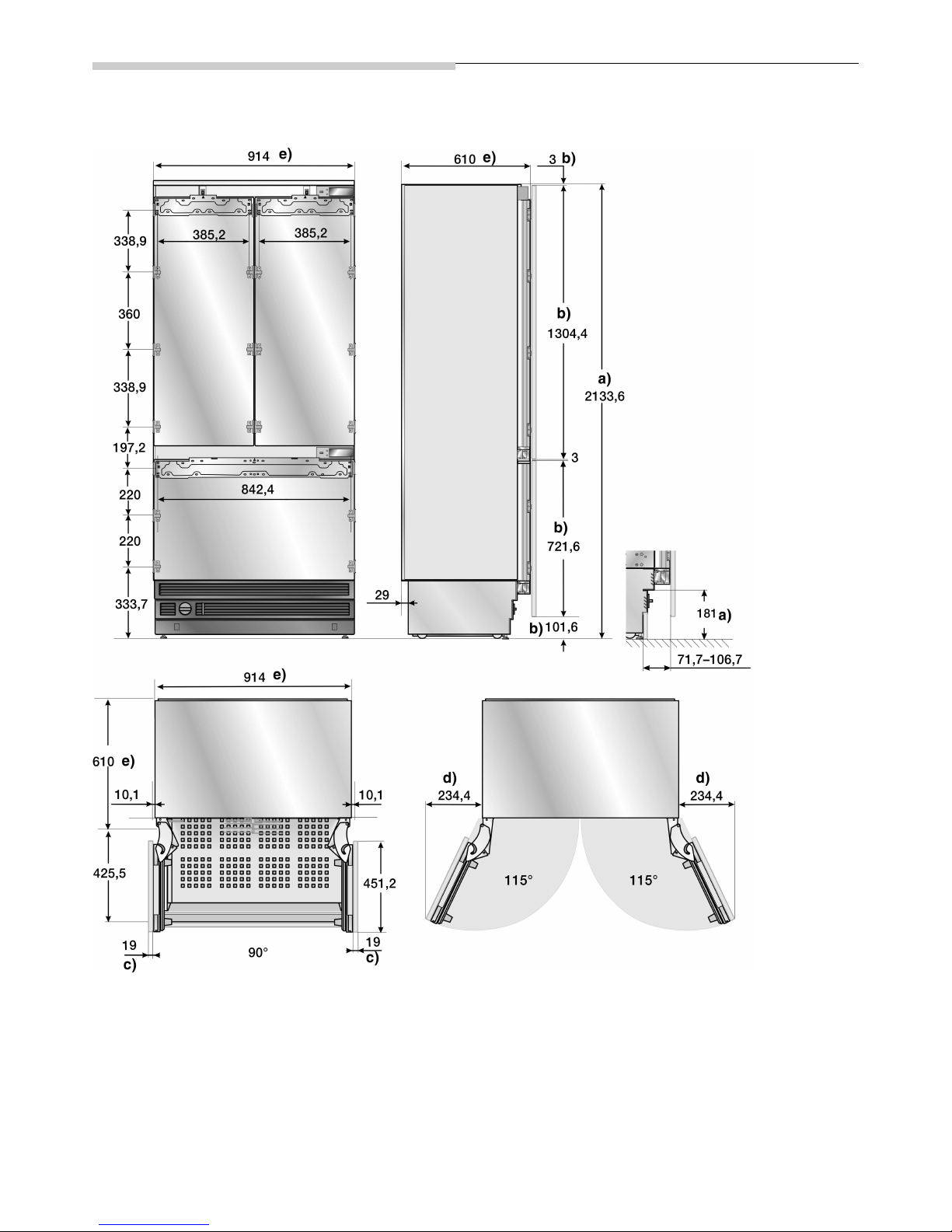
Appliance dimensions .......................................... 8
Tools and Accessories which are needed ........... 9
Scope of delivery .................................................... 9
Additional accessories ............................................ 9
Tools ...................................................................... 9
Miscellaneous ......................................................... 9
Installation manual ............................................... 10
1. Checking the installation niche ........................ 10
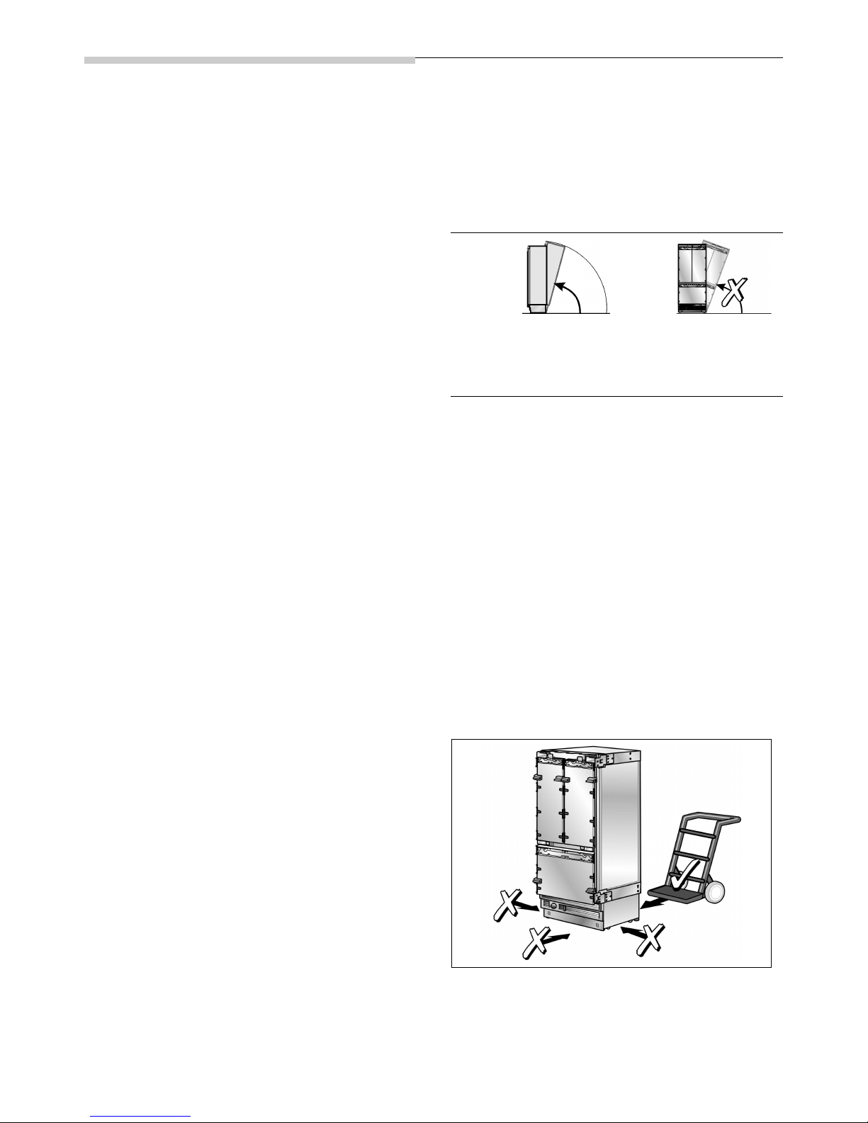
2. Transporting the appliance ............................. 10
3. Removing the packaging ................................ 10
4. Preparing the appliance .................................. 11
5. Preparing the installation niche ....................... 11
6. Attaching an additional anti-tilt mechanism ..... 12
7. Preparing the water connection ...................... 13
8. Attaching the edge protectors ........................ 13
9. Sliding the appliance into the installation niche 14
10. Adjusting the appliance in the niche ................ 15
11. Fixing the appliance to the niche ceiling .......... 16
12. Fastening the appliance to the side wall
of the installation niche ................................... 16
13. Connecting water to the appliance ................. 17
14. Attaching the base strip .................................. 17
15. The appliance is switched on .......................... 18
16. Preparing the furniture doors .......................... 18
17. Loading the appliance door ............................ 19
18. Attach the adjusting rib to the furniture door
(refrigerator compartment) .............................. 19
19. Hang and align the furniture door
(refrigeration compartment) ............................. 20
20. Attach the adjusting rib to the furniture door
(freezer compartment) ..................................... 21
21. Hang and align the furniture door
(freezer compartment) ..................................... 22
22. Fix the furniture door
(refrigerator compartment) .............................. 23
23. Fix the furniture door
(freezer compartment) ..................................... 24
24. Screw on the lower fixing angle ...................... 24
25. Fasten the finger protector .............................. 25
26. Attaching the covers ....................................... 26
27. Mounting the air separator .............................. 27
28. Setting the door opening angle
(refrigerator compartment door) ...................... 27
29. Tense the hinge screws
(refrigerator door) ............................................ 27

3
Important Information
mCaution!
Setting up and mounting this appliance requires
extensive expertise in various trades (mechanics,
carpentry, plumbing, electrics).
It is the duty of the person setting the appliance up to
guarantee that it is set up and commissioned securely.
Mistakes in setting the appliance up and damage
resulting from this do not come under the warranty
of the manufacturer. Terms of guarantee are found
in the operating instructions of the appliances.
mWarning!
The appliances are very heavy and must be secured from
tipping when transporting, when mounting and when
operating. It is absolutely necessary to fit an anti-tip device.
Keep the doors closed until the appliance has been
mounted completely and secured according to the
instructions in these mounting instructions.
Because of the weight / dimensions of the appliance and
to minimise the risk of injuries and damage to the appliance
at least two persons are necessary to set-up the appliance
securely.
Use the appliances according to the prescribed
application.
Pull out the plug or remove the fuse before commencing
work on the appliance.
Only allow a specialist electrician to exchange a mains lead.
Only allow customer service to carry out repairs to the
appliance.
Apart from statutory national regulations, you should stick
to the connection terms relating to the local electricity and
water companies.
These mounting instructions are designed to help you
install your new appliance.
The manufacturer cannot be held liable for mounting which
has been improperly carried out. We recommend that you
allow a qualified specialist to set up and switch the
appliance on for the first time.
Following all information and keeping to the instructions are
preconditions for mounting and switching the appliance on
safely for the first time.
Keep the mounting instructions safe for use later on.
Before setting up and switching the appliance on for
the first time, read the mounting instructions fully and
thoroughly.
Installation Possibilities
Various installation possibilities are available.
These are only limited by the kitchen design and the finger
protection function.
Stand alone appliance
Stand alone appliance with dividing wall
Note:
– When measuring the dividing wall for model 2,
pay attention to the thickness of the furniture front to
be mounted in order to avoid damage when opening
doors at the same time.
– If the distance between the appliances is less
than 160 mm, the heating kit for the side-by-side
combination should be used.
For further information see section “Additional
acessories” on page 9.
– The minimum thickness of the dividing walls is 16 mm.
As an end section to a row of kitchen
units
If a side of the appliance is visible, use a side covering.
The side covering must be connected firmly to the wall,
the floor and the upper cupboards before the appliance is
slid into the installation niche.
The dimensions of the side covering are governed by the
opposing niche wall. During installation, make sure that the
installation niche has right angles and has the exact size
necessary for the appliance.

4
Installing the appliance
Installation location
The appliance should be installed in a dry, well ventilated
space.
The location should not be exposed to the direct sunlight
and should not lie next to a source of heat such as
a cooker or a radiator etc. If installation next to a source of
heat cannot be avoided, either a suitable insulating plate
should be used or you should keep to the following
minimum distances:
– 30 mm from the electric cooker,
– 300 mm from a oil-fired or solid-fuel cooker.
mCaution!
The appliance is very heavy.
Empty weight: 195 kg
Atmosphere grades
The atmosphere grade is written on the identification plate.
It states the room temperature within which the appliance
can be operated.
Installation niche
It is important to keep to the stated dimensions of the
installation niche with a view to trouble-free fitting, and the
subsequent appearance of the kitchen furniture frontage.
Special care should be taken that the niche has right
angles. The side walls should not exhibit areas that stick
out, projections or unevenness.
You should determine the right angles of the installation
niche with appropriate means, e.g. by measuring
diagonally and by using a spirit level.
The side walls and the upper end of the installation niche
must be at least 16 mm thick.
Neighbouring kitchen furniture
The new appliance is screwed down tightly using parts
of the cabinet and the upper cabinet.
Care should therefore be taken, that all upper cabinets
to which something has been fastened are securely
connected to the subsurface or wall by appropriate
means.
The minimum thickness of the base should be a minimum
of 19 mm.
Subsurface
mCaution!
A fully laden appliance is heavy.
Weight: up to 540 kg
The subsurface must be level and even in order to ensure
that the appliance is securely installed and works correctly.
The subsurface must be made from a hard, non-flexible
material.
The floor of the installation space must have the same
height as the rest of the space.
On account of the weight of a fully-laden appliance, it is
necessary to have a bearing subsurface. In the case of
doubt, the help of architect or specialist builder should
be enlisted.
Atmosphere
grade
Permitted ambient
temperature
SN +10 °C to 32 °C
N +16 °C to 32 °C
ST +16 °C to 38 °C
T +16 °C to 43 °C

5
Electrical connection
Do not use an extension lead or a multi-plug socket.
Connecting this appliance, only use a plug which has
been installed securely.
The plug to secure the appliance must be freely accessible.
Connect the appliance to a 220–240 V/50 Hz ac current
via a plug which has been properly installed. The socket
must be fused with a 10 to 16 A fuse.
For appliances operated in non-European countries,
the identification plate should be checked whether the
electric supply and the current model stated match the
vales of the mains supply. For details regarding the position
of the identification plate, see section “Calling Customer
Service / Identification Plate”. Any necessary exchanging of
the mains lead should carried out by a specialist electrician.
mWarning!
On no account should the appliance be connected to
electric saving plugs or to converters which convert dc
current to 230 V ac e.g. solar appliances, marine
current mains networks.
Water Connection
A cold water connection is necessary for operating the
automatic ice maker. The water pressure must lie between
1.7 and 10 bar. The installation must correspond to the
local plumbing regulations.
A separate shut-off valve should be installed in the cold-
water inflow.
The shut-off valve should not be located behind the
appliance. It is recommended that you mount the shut-off
valve directly next to the appliance or at another place
which is easily accessible.
When installing the water connection, pay attention to the
permissible installation area for the water mains. For more
information concerning the permissible installation areas,
see the section “Installation Dimensions”.
Note:
The maximum outside diameter of the water mains (without
connecting pieces) is 10 mm.

6
Dimensions of the Installation Niche
Setting-up as an stand alone appliance
Key:
A Area for installation of the water connection
The shut-off valve for the appliance’s water
connection is to be located in the immediate vicinity
of the installation niche such that it is accessible
without disassembling the appliance. If this is
absolutely unavoidable, the shut-off valve should be
only be installed in the area of the installation areas
labelled with A and B behind the appliance.
B Area for installation of the electric current
D Depth of the installation niche, depending on the
kitchen design
D = 610 mm minimum!
Note:
The installation niche must have right angles. The side
walls should not exhibit areas that stick out, projections
or unevenness.
Important!
The upper niche wall must consist of a rigid, load bearing
material (minimum thickness 16 mm). The upper niche wall
must be completely even up to a depth of at least 100 mm
and free from bumps.
Important!
The lateral niche walls must be completely even and free
from bumps. If the niche is formed as a separate part, the
side walls must be completely even up to a depth of at least
100 mm and free from bumps.

7
Site of the water connection
The mains supply can be laid to the appliance from the
right-hand side (a), from the left-hand side (b) or from the
space below the appliance (c).
Key:
A Area for installation of the water connection
B Area for installation of the electric current

8
Appliance dimensions
Key:
An example is shown with a continuous furniture frontage.
a) The adjustment range of the appliance feet is
+35 mm/–13 mm.
b) Dimensions can vary
c) The thickness of the door covering can vary
d) This dimension can vary, depending on installation,
thickness of the furniture door to be mounted and
the neighbouring kitchen furniture.
e) Dimensions of the appliance
f) Dimensions of the furniture door

9
Tools and Accessories which
are needed
Scope of delivery
– Installation manual
– Operating instructions
– Installation accessories
Additional accessories
– Lateral additional heating
Necessary when the distance between
two appliances is less than 160 mm.
– Finger protection, extra long
– Connecting element for furniture doors
For connecting two furniture doors (see explanation on
page 32). It can be used for standard height furniture
doors without any preparation work.
Tools
– T20 rechargeable screwdriver
– T20 Torx screwdriver
– T20 Torx-bit magnetic holder
– 8 mm socket wrench
– Various size drills
– Fixed spanner SW 13 mm
– Adjustable spanner
– Knife with an adjustable blade
– Metal tape measure
– Angle of contact
– 60 cm and 120 cm spirit levels
– Straight edge
for stand-alone appliances min. 120 cm long
for setting up two appliances side-by-side min 200 cm
long
Miscellaneous
– Step ladder
– Trolley, wheelbarrow or sack barrow
– Hammer drill for drilling holes into the wall and floor
– Various size drills for various materials
– Wood plank, (min. 8 x 10 cm) as an alternative anti-tip
device. Length should correspond to the width of the
installation niche.
– Various size wood screws
– Thin (1.5 mm), suitable material to protect the floor
against damage (e.g. linoleum)
– Suitable material for covering and protecting the
cabinets (e.g. protective film)
– Adhesive tape

10
Installation manual
mCaution!
The following mounting instructions describe
mounting steps for various appliance models.
Therefore, deviations may occur from that shown
in the diagrams.
Reference is made to specific mounting steps for
individual appliances.
1. Checking the installation niche
mWarning!
In order to guarantee secure, trouble-free installation
and an optimal overall impression of the adjacent
cabinet frontage careful care should be taken in
ensuring that the installation niche corresponds to
the installation requirements.
Before starting with the installation, check that the
installation niche corresponds to all of the requirement for a
secure and trouble-free installation.
Check the subsurface.
Follow the notes in the section “Installation location”.
Check the dimensions of the niche.
Re-examine whether the niche has right angles.
Re-examine the positioning of the plug.
Additionally follow the instructions in the sections
“Electrical Connection” and “Dimensions of the
Installation Niche”.
Re-examine the positioning of the water connection
(for appliances with ice maker)
Additionally follow the instructions in the sections
“Water Connection” and “Dimensions of the
Installation Niche”.
Re-examine the stability and fastening of the
neighbouring cabinet parts. All cabinet parts in the
vicinity of the appliance have to be firmly connected
to the wall.
Re-examine that when opening the appliance door,
it does not collide with neighbouring kitchen parts.
2. Transporting the appliance
mCaution!
The appliance is very heavy. Handle it carefully,
as otherwise people helping to lift it could be hurt
or the appliance could be damaged.
Transport the appliance with an aid to transport which
is suitable (sack barrow, trolley or wheelbarrow).
When transporting, secure the appliance from being
tipped.
The appliance has a height of 2134 mm. If it is not possible
to support the appliance in a vertical position because of
the structure of the building, the appliance can be
transported on its side.
When putting the appliance up, pay attention to the
minimum height that is required at the assembly location
according to the following table.
3. Removing the packaging
mCaution!
– The appliance could tip over when unpacking.
– The appliance is very heavy.
– The appliance could tip over when the appliance
door is opened.
Handle it carefully, as otherwise people helping to lift it
could be hurt or the appliance could be damaged.
To protect the subsurface from damage whilst installing:
Put a carpet or spare piece of linoleum (or other such
item) down and attach it to the floor using adhesive
tape in front of the planned fitting site.
mWarning!
Always place the means of transport centrally on the
rear side of the appliance. Never push it in from the
front or from the side under the appliance.
Risk of damage to the appliance!
Move the appliance using a trolley, sack barrow or
wheelbarrow.
Putting the appliance
up on via its back side
Putting the appliance
up on via its rear side
wall
All types
218,5 cm
Never put the
appliance up via
its side!

11
Removing the transportation packaging:
Remove the cardboard. Be careful when using
the knife so as not to damage the surface of the
appliance.
Take the supplied accessories from the protective
parts of the packaging.
mWarning!
Only remove the transporting securing units with which
the slide-in bases and the storage compart-ments in
the appliance are protected after completing the
installation as otherwise, parts could be damaged.
Check the appliance for damage.
Do not install the appliance if there is visible damage.
If there are queries, please contact the dealer.
4. Preparing the appliance
Remove the lateral fastenings and fastening sheets
with which the cabinet fronts are attached. To do this,
loosen the fastening screws and remove the stops.
Note:
Keep the stops safe as otherwise they may become lost.
5. Preparing the installation niche
Note:
For each appliance, two anti-tilt ribs are needed.
Determine the fastening points of the anti-tilt ribs.
Determine the actual dimensions according to the
section “Installation Dimensions”.
mCaution!
Ensure that in the wall area there are no electrical wires
or pipes which could be damaged by pipes. Risk of
injury or damage!
If a installation niche is deeper than the appliance, lay a
strong wooden plank behind the anti-tilt ribs
and screw tightly to the subsurface or the wall.
The length of the plank should correspond to the width
of the installation niche!
Important note:
As far as possible, always screw the wooden plank
to the rear wall of the niche.
In the case of some fitted shapes, it may be necessary to
screw in at an angle the wood screws used to fasten the
anti-tilt ribs to the rear wall.
Important information for securing against tilting:
– The set supplied, contains fastening screws for
various subsurfaces. Select the fastening screws
corresponding to the local conditions.
– If it is not possible to securely fasten the anti-tilt ribs
and consequently, not possible to securely fasten the
appliance using the fastening screws supplied, select
another suitable method for securely fastening the
anti-tilt ribs.
– In the case of some fitted shapes, it may be necessary
to screw in at an angle the wood screws used to
fasten the anti-tilt ribs to the rear wall.

12
Subsurface wooden floors
The wood screws (5 x 60 mm and 4 x 15 mm) which are
supplied should be used for wooden floors.
Drilling guide holes:
3 mm for woodscrews (5 x 60 mm)
2 mm for woodscrews (4 x 15 mm)
Make sure that the screws 5 x 60 grip at least 19 mm
into the solid subsurface.
Tightly screw the anti-tilt ribs. Re-examine to make
sure that the screws are firmly tightened.
Subsurface concrete
mWarning!
When installing or working with floor anchors always
use protective glasses and other protective equipment
or protective clothing – risk of injury!
Floor anchors are not suitable for use in connection
with lightweight construction masonry, breeze blocks
or tiles.
Never use floor anchors in fresh concrete which has
not hardened.
In drilling holes for these floor anchors, do not use core
drills.
Use a floor anchor M8 and a screw M8. Additionally use
the (5 x 60 mm und 4 x 15 mm) woodscrews supplied.
Drill a hole with a 10 mm diameter having a depth
a little more than the raising depth. Use the drill
supplied.
Clean the hole or drill a little deeper.
By hand, screw into the dowel until you can feel
resistance.
Strike the dowel and screw into the hole until the head
of the screw has a 13 mm distance to the anti-tilt
securing device.
Screw tightly.
Additionally use the supplied wood screws
(if the subsurface allows).
6. Attaching an additional anti-tilt
mechanism
Important note:
As far as possible, always screw the wooden plank to the
rear wall of the niche.
If the anti-tilt ribs cannot be fastened securely, a wooden
beam can be used above the appliance as an alternative
anti-tilt mechanism. Care should be taken that there is not
a gap between the appliance and the wooden beam.
Cut the wooden plank to the required length
(cross section min. 8 x 10 cm).
The length should correspond to the width of the
installation niche!
Note:
– If the installation niche is deeper than the appliance,
select a stronger beam or use two, one behind the
other.
– The plank must overlap the appliance by at least
50 mm.

13
Mark the installation height (underside edge of the
plank) on the rear wall of the niche.
Select the screws according to the thickness of the
wooden plank: Length min. 2.5 x wood thickness,
diameter 12 or 14 mm.
Select the number of screws corresponding to the
niche width so that you ensure that the plank can be
securely mounted.
According to the subsurface:
Look for the supports on the rear wall of the niche and
mark the drill holes on the plank corresponding to the
position of the support.
or
Fasten suitable dowel into the rear wall.
Pre-drill.
Screw the plank onto the rear wall of the niche.
7. Preparing the water connection
(only for appliances which require a water connection)
mWarning!
Turn off the main water tap in order to avoid damage
from escaping water.
Lay the connection pipe. Always keep to the given
installed area in order to avoid damaging the
connection pipe when sliding the appliance in later.
Fix the connection pipe to the floor with adhesive tape.
8. Attaching the edge protectors
In order to protect the edges of the installation niche,
attach the supplied protection ribs with adhesive tape.

14
9. Sliding the appliance into the installation niche
Note:
If the floor or appliance is skew in relation to the installation
niche, the height-adjustable wheels should be correspon-
dingly adjusted before sliding the appliance into the niche.
Plug the mains plug into the socket.
Note:
A separate plug is necessary for each appliance in the case
of side-by-side set up!
Protect the mains lead from getting wedged under
or behind the appliance.
Recommended procedure:
Tie a rope onto the middle of the mains lead and slide
the appliance forwards. Pull the cable onto the rope
when sliding the appliance into the niche.
or
Fasten the mains lead onto the floor with adhesive
tape, in the middle behind the appliance approx.
38 cm from the rear of the niche.
Slide the appliance carefully into the niche until
the height-adjustable wheels grip into the anti-tilt
mechanism.
mWarning!
Be careful when sliding the appliance into the
installation niche. The water connection or mains
fixed on the floor could be damaged.
Remove the edge protector of the installation niche.

15
10. Adjusting the appliance in the niche
Adjust the appliance to the existing furniture.
Keep the straight edge on the door, above the
positioning supports.
The positioning supports are set out for the following
overall strengths of the furniture doors to be mounted.
–19mm
–38mm
Re-examine the actual thickness of the doors to be
mounted in order where necessary, to be able to
compensate possible digressions.
The height-adjustable feet on the front and rear can
all be adjusted from the front.
Front: with a fixed spanner SW 13 mm
Rear: with a socket spanner with flexible shaft
mCaution!
Never use a rechargeable screwdriver for setting
the height of the appliance.
A mark is made on the base of the appliance which serves
as a standard measurement for setting the height.
When setting the height, raise the mark to 32 mm above
the ground.
Screw the height-adjustable screws as far down-
wards as possible until the marking on the base has
reached the given height (32 mm).
Note:
This dimension is very important for the subsequent
adjustment of the cabinet frontage.
Adjust the front of the appliance with the spirit level.
Note:
– Do not tip the appliance in the niche! When screwing
down the height adjustable feet, proceed step by step.
Lower by alternating left to right.
– The rear feet can be set easier when the appliance
is not loaded on the rear.
– When using a wooden plank as an alternative anti-tilt
mechanism as in point 7 of these mounting instruc-
tions, turn the appliance as far as it will go against the
wooden plank. Do not bend against the wooden
plank.

16
11. Fixing the appliance to the niche
ceiling
Screw on the front bars of the fastening sheets (above)
with the upper cabinets.
Fasten the lateral bars of the fastening sheets (above)
in each case, according to the installation conditions.
If there is no or only a small crack available, the lateral
bars do not have to be fixed.
If there is a large crack available above the appliance,
integrate a wooden plank above the appliance and
pay attention that the crack is completely filled
Attach the covering ribs onto the fastening sheets
(above), cut the connection ribs to the desired height!
12. Fastening the appliance to the side
wall of the installation niche
Screw on the bars of the fastening sheets (lateral)
with the cabinet parts located next to them.

17
13. Connecting water to the appliance
Supplied, is a flexible hose for a domestic mains
connection ¾”. Care should be taken than the supplied
sealing elements are mounted on the appliance and the
shut-off valve!
mWarning!
Do not kink the hosepipe when bending, otherwise
there is the risk of water damage and leakage.
Remove the plugs from the appliance connection (1).
Lay the water hose such that it ends at the appliance
connection (2).
Slide the union nut and the sealing element onto the
water hose.
Attach the water hose to the appliance connection
and screw on the union nut (3). Screw tightly, using
manual force.
Screw the union nut tightly using the fixed spanner. Do
not over tighten!
Turn the shut-off valve and the main water tap.
Re-examine the point of connection at the shut-off
valve and the appliance connection for leaks.
14. Attaching the base strip
mWarning!
From the floor upwards, the maximum height of the
base strip is 10.1 cm. Never cover the ventilation
cracks in the base panelling. Risk of damage to the
appliance.
Where necessary, cut the base strip to the required
length.
Attach base panelling to the appliance.
Take the protective film off from the adhesive pads
on the Velcro strip.
Put the base strip onto the base panelling and push
firmly.
Measure the difference in depth Y between the base
panelling and the base strip of the adjacent lower
cabinets.
Remove the base panelling again.
Loosen the fastening joint of the base panelling.

18
Take out/slide in the joint around the measured
depth Y.
Screw the joint again tightly.
Fasten the base panelling.
Note:
If necessary, the base strip can also be screwed to the
base panelling. Pre-drilled screw holes are located in the
base panelling in the area of the Velcro strip.
15. The appliance is switched on
The appliance should now be switched on for the first time
in order to ensure the accuracy of the following mounting
steps and with it, the appearance of the entire kitchen
frontage.
Open the appliance door.
Actuate the appliance’s on/off button.
Only for appliances with a water connection:
In the case of possible damage of the water mains, keep
the shut-off tap closed in order to avoid the risk of damage
from water coming out.
16. Preparing the furniture doors
Important note:
When working on the furniture doors, care should be taken
to the following:
– Always carry out screwing jobs on the most stable part
of the furniture door. Never screw into fillings or similar
areas.
– Always selects screws with a length smaller than the
thickness of the cabinet front.
– Protect the surfaces of the furniture doors during
installation against damage.
The overall weight of the furniture door including the handle
should not exceed the following values:
The furniture doors are attached to the appliance with the
fastening elements located on the appliance. Using these
fastening elements, this allows the furniture door to be
adjusted accurately and securely attached to the
appliance.
Overall width of the
furniture door
Refrigeration compartment door 2 x 5 kg
Freezer drawer 10 kg

19
Function of the various parts:
1. Threaded rod on the adjusting rib:
for adjusting the furniture door vertically.
2. Fixing angle:
for adjusting the cabinet frontage in terms of depth.
3. Nuts on the threaded rod:
for securing the cabinet front in order to prevent lateral
sliding.
4. Lower fixing angle:
for securing the cabinet front in order to prevent lateral
sliding
Connecting element for furniture doors
Instead of one large door, two furniture doors can be
mounted next to each other in the case of appliances
with a width of 91 cm. These furniture doors are then
connected using a metal strip on the rear.
This metal strip is available from your dealer as an
installation accessory (Connection element for furniture
doors). For further details see section “Tools and
Accessories which are needed”.
When attaching the metal strip to the furniture doors,
watch out for the maximum possible length of the screws
and the position of the drill holes. Always carry out
screwing jobs on the most stable part of the furniture door.
Never screw into fillings or similar areas.
Note:
If only one door is to be mounted to an appliance with
a width of 91 cm, attach the supplied sandwich plate to the
adjusting rib and fix into position.
17. Loading the appliance door
When attaching the furniture doors it is recommended to
load the storage sections in the door with weights in order
to ensure that the when adjusting crack dimensions turn
out to be as precise as possible.
Loading recommendations:
18. Attach the adjusting rib to the
furniture door (refrigerator
compartment)
Note:
The adjusting rib is the most important tool for adjusting the
cabinet frontage.
Unscrew the positioning aids from the appliance door.
The positioning aids will still be needed in the course
of mounting.
Remove the covering rail from the freezer room
drawer.
Overall width of the
furniture door
Refrigeration compartment door 2 x 12 kg
Freezer drawer 10 kg

20
Measure the distance X between the adjusting rib and
the upper edges of the neighbouring furniture doors.
Mark this value X on the rear side of the furniture door.
Determine the middle of the door and label it.
Loosen the two nuts and remove the adjusting rib.
Rest the adjusting rib on the furniture door and align to
the markings. Mark the drill holes.
Pre-drill the holes.
Tightly screw the adjusting rib.
Note:
– Attach the adjusting rib with at least 6 screws on the
furniture door. One screw should be screwed in under
the threaded rod in each case.
– The adjusting rib has a various holes for different
furniture door design variations. Always carry out
screwing jobs on the most stable part of the furniture
door.
19. Hang and align the furniture door
(refrigeration compartment)
Note:
The height of the cabinet frontage is set using the threaded
rod.
Hang the furniture door on the threaded rod.
Adjust the furniture door using the threaded rod
(Torx screwdriver)
Transfer the middle drilled holes on the outside edge
of the appliance door to the furniture door.
Remove furniture door.
Other manuals for K7791X0
3
This manual suits for next models
1
Table of contents
Other NEFF Refrigerator manuals

NEFF
NEFF K5660X0 User manual

NEFF
NEFF K59..X Series Manual

NEFF
NEFF KI1413FF0G/01 User manual

NEFF
NEFF KI12 Series User manual

NEFF
NEFF KI8815OD0 Specification sheet

NEFF
NEFF KI2822SF0 User manual

NEFF
NEFF K7961X0 User manual

NEFF
NEFF KI841 Series User manual

NEFF
NEFF KI58 Series User manual

NEFF
NEFF KI8816DE0G User manual

NEFF
NEFF KI1413D30 User manual

NEFF
NEFF KI852 Series User manual

NEFF
NEFF KA7902i30 Operation manual

NEFF
NEFF K431 User manual

NEFF
NEFF KI5871SF0G/01 User manual

NEFF
NEFF KI141 Specification sheet

NEFF
NEFF K58 series User manual

NEFF
NEFF K81 Series User manual

NEFF
NEFF K59..L User manual

NEFF
NEFF K44 User manual