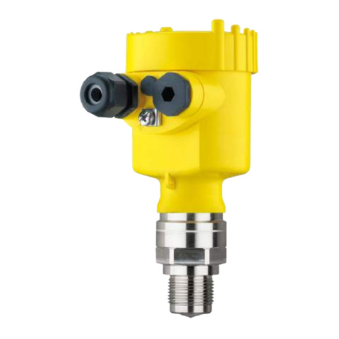
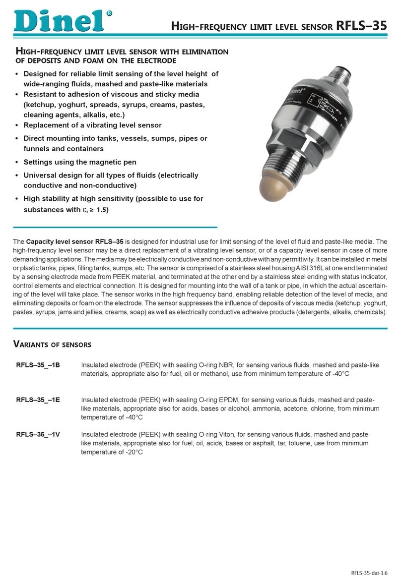
Negele LAR-361 User manual

Negele Messtechnik GmbH ∙ D-87743 Egg a. d. Günz ∙ Telefon +49 (0) 83 33 / 92 04-0 ∙ Fax +49 (0) 83 33 / 92 04-49 ∙ www.negele.net
1
Application / Specifi ed usage
·· Hydrostatic level measurement in humid ambiance
·· Special applicable for exterior storage vessels
Application examples
·· Level measurement with LAR, linearization and evaluation with PEM-DD
(6 standard geometries, 1 geometry programmable; see separate product
information)
·· Difference pressure measurement with 2 x LAR and evaluation device PEM-DD
Hygienic design / Process connection
·· By using the Negele weld-in sleeve EMZ-352 or the build-in system
EHG-.../1" a front-fl ush, hygienic and easy cleanable measurement
point will be achieved.
·· EHEDG certifi cate for hygienic process connection CLEANadapt (LAR-361)
·· 3-A-certifi cate for versions with TriClamp DIRECTadapt (LAR-761)
·· CIP- / SIP-cleanable up to 140 °C (284 °F) / max. 30 min
·· Front-fl ush stainless steel sensor cell
·· All wetted materials are FDA-conform
·· Sensor completely made of stainless steel
·· Protection class IP 69 K (with cable connection)
·· Available process connections (adapter):
Tri-Clamp, SMS, DRD, Varivent, BioControl
Features / Advantages
··Measurement cell without any contact to atmosphere, fully closed
measurement system
·· No drift problems caused by condensation
·· Very high accuracy and long term stability
·· Measurement up to 130 °C (265 °F) medium temperature
·· Oil fi lling, FDA approved
·· Factory or fi eld calibration
·· Integrated two-wire measurement trancducer 4...20 mA
··3 years warranty
Options / Accessories
·· Material certifi cate 3.1
·· Special pressure ranges, specifi c pressure calibration ex works
·· Electrical connection with M12 plug-in connector
·· Preassembled cable for M12 plug-in connector
Measuring principle
The pressure sensor utilizes an internal piezoelectric transducer to convert
the mechanical pressure into a corresponding mV signal. The mV signal then
passes through custom linearization and conditioning circuitry. The resulting
signal is an industry standard 4...20 mA, according to the specifi ed range.
In addition, onboard circuitry handles temperature compensation to ensure a
stable reading during all phases of operation.
Authorizations
Product Information LAR-361 | LAR-761
Climatic Independent Level Sensor LAR
LAR-361 with EMZ-352
Measuring principle
atmospherical
pressure
temperature
sensor 1
hydraulic
coupling
piezoelectric
transducer
hydraulic
coupling
temperature
sensor 2
hydrostatic pressure
+ atmospherical
pressure
TYPE EL
March 2006

Negele Messtechnik GmbH ∙ D-87743 Egg a. d. Günz ∙ Telefon +49 (0) 83 33 / 92 04-0 ∙ Fax +49 (0) 83 33 / 92 04-49 ∙ www.negele.net
2
Specification
Specification
Pressure ranges, standard relativ 0...0,35 / 1,0 / 2,0 /3,3 / 4,0 bar
Over-range rating factor 2 times base range
Process connection LAR-361: CLEANadapt thread G1" sensor, combined with
Negele CLEANadapt process connection,
torque max. 20 Nm
LAR-761: DIRECTadapt Tri-Clamp 1...1½" or 2"
coupling nut RD 52 x 1/6 for universal adapter 44 mm
thread M38 x 1,5
Materials connector head SS 316 (1.4305), Ø 65 mm
thread connection SS 316L (1.4404)
diaphragm SS 316L (1.4404), Ra < 0,4 µm
oil filling Drakeol 35, Drakeol 10B, FDA approval number
21CFR172.878, 21CFR178.3620, 21CFR573.680
Temperature ranges ambient -10...+50 °C (15...120 °F)
process -20...+130 °C (0...265 °F)
compensated -20...120 °C (0...250 °F)
CIP / SIP 140 °C (284 °F) max. 30 min.
Temperature compensation time
T90 30 s / 10 K
Accuracy hysteresis ≤ 0,075 % of full scale
linearity ≤ 0,05 % of full scale
reproduceability ≤ 0,075 % of full scale
Temperature drift zero < 0,04 % of full scale / K
span < 0,04 % of full scale / K
Electrical connection cable gland M16 x 1,5 (PG)
cable connection M12 plug-in SS 316 (1.4305) (option)
Protection class IP 67 (with cable gland)
IP 69 K (with cable connection)
Supply voltage 12...40 V DC
Output 2-wire current loop analog 4...20 mA short circuit proof
Max. loop resistance power supply max. resistive load
(not incl. LAR) 18 V DC 300 Ω
24 V DC 600 Ω
40 V DC 1200 Ω
Weight approx. 1050 g
Pressure ranges
Type min. operation range max. operation range over-range rating
LAR-x61 / 0 0…0,1 bar 0…0,35 bar 0,6 bar
LAR-x61 / 1 0…0,35 bar 0…1,0 bar 2,0 bar
LAR-x61 / 2 0…1,0 bar 0…2,0 bar 4,0 bar
LAR-x61 / 3 0…2,0 bar 0…3,3 bar 6,6 bar
LAR-x61 / 4 0…3,3 bar 0…4,0 bar 8,0 bar

Negele Messtechnik GmbH ∙ D-87743 Egg a. d. Günz ∙ Telefon +49 (0) 83 33 / 92 04-0 ∙ Fax +49 (0) 83 33 / 92 04-49 ∙ www.negele.net
3Dimensioned Drawings | Installation
Mechanical connection / Installation
·· Pay attention to the maximum tightening torque of 20 Nm if using Negele CLEANadapt system!
·· Pay attention to remain open the 4 ports of atmospheric vent location.
LAR-361 | G1" CLEANadapt LAR-761 | Tri-Clamp
atmospheric
vent location
atmospheric
vent location
LAR-761 | EHS LAR-761 | HPV
atmospheric
vent location
atmospheric
vent location
Tri-Clamp size
Type Ø D
TC1 50,5 mm
TC2 64 mm
54
65
100
G1"
72
54
65
ØD
Ø65
54
73
RD 52 x1/6
54
65
105
M38 x 1,5

Negele Messtechnik GmbH ∙ D-87743 Egg a. d. Günz ∙ Telefon +49 (0) 83 33 / 92 04-0 ∙ Fax +49 (0) 83 33 / 92 04-49 ∙ www.negele.net
4
20
12
4
0
50 1000
20
12
4
0
50 1000
Electrical Connection | Installation
Electrical connection With M12-plug
Configuration M12-plug
1. supply +24 V DC
2. output 4...20 mA
3. not connected
4. not connected
4...20 mA
2-wire current loop
Start up
·· Connect the sensor with power supply (12…36VDC) -> see “electrical connection LAR”.
·· The sensor is now ready for use.
·· At standard factory-setting 0...100 % of the full range are equivalent to 4...20 mA of the current output.
Example: LAR-xxx/1 = 0...1 bar -> 0 bar = 4 mA; 1 bar = 20 mA
·· In case of specific factory calibration the customized measurement range is equal to 4...20 mA of the current output.
Example: LAR-xxx/1 calibrated to 0...0,8 bar -> 0 bar = 4 mA; 0,8 bar = 20 mA
·· Calibration is on-site customizable for special measurement tasks.
·· Settings of ZERO (4 mA) and SPAN (20 mA) are non-interactive, having no effect on each other.
Empty adjustment Empty adjustment (with empty vessel)
·· After mounting an empty adjustment is strongly
recommended, because mounting position can affect
the ZERO setting.
·· Empty vessel completely (no pressure or product on
diaphragm, vessel is vented to atmosphere)
·· Switch in position “RUN MODE”
·· Actuate key switch “ZERO” for 5 seconds
·· Empty adjustment is done.
·· Output current is 4 mA.
·· For maximum accuracy we advice an empty adjustment
one more time after 3 weeks.
·· After that an annually empty adjustment is
recommended.
Level / Pressure [%]
Current output [mA]
Press “ZERO”-button
for 5 seconds
Full adjustment 1. Full adjustment (with filled vessel utilizing level
in vessel)
·· Fill vessel to desired maximum level
·· Please pay attention that hydrostatic pressure must
be between min. and max. range of sensor
(see table of pressure ranges page 2).
·· Switch in position “RUN MODE”
·· Actuate key switch “SPAN” for 5 seconds
·· Full adjustment is done.
·· Output current is 20 mA
Level / Pressure [%]
Current output [mA]
Press “SPAN”-button
for 5 seconds

Negele Messtechnik GmbH ∙ D-87743 Egg a. d. Günz ∙ Telefon +49 (0) 83 33 / 92 04-0 ∙ Fax +49 (0) 83 33 / 92 04-49 ∙ www.negele.net
5Installation
2. Utilizing on-board setup
If “wet calibration” (by vessel filling) is not possible, full adjustment can be done by on-board setup.
First of all, the desired range (full value) must be calculated to a corresponding current value.
Afterwards, the calculated current will be adjusted by multimeter to perform new calibration.
In the following, a current calibration procedure is described as an example.
Calibration hookup
4...20 mA
2-wire current loop
Multimeter
LAR calibration values
Type Base range
in bar
Upper
lineariza-
tion value
in bar
Current
CAL at
base range
in mA
LAR-x61/0 0,35 0,3612 19,50
LAR-x61/1 1,00 1,0462 19,29
LAR-x61/2 2,00 2,0799 19,39
LAR-x61/3 3,30 3,4623 19,25
LAR-x61/4 4,00 4,0228 19,91
2.1 Calculating the current to adjust
For calculating the current to adjust the “upper linearization value” is needed (see table calibration values).
This linearization value is greater than the base range. LAR needs this value to calculate the characteristic line.
Calculation formula:
(( desired range / upper linearisation value ) * 16 ) + 4 = current to adjust
Example:
LAR-361/1 needs to be calibrated to 0,8 bar: (( 0,8 / 1,0462 ) * 16 ) + 4 = 16,23 mA
2.2 LAR adjustment
·· Connect LAR with power supply -> see figure calibration hookup above.
·· Perform meter hookup with test points (setting mA/DC).
·· Set MODE SWITCH to “FIELD CAL”.
·· Meter output will automatically move to 19,99 mA – LAR is waiting for entry of new calibration range.
·· Using the switches “SPAN” and “ZERO”, raise or lower the current until the calculated value (see above) has
been reached.
·· Once the proper value has been reached, simultaneously depress both the “SPAN” and the “ZERO” switch for one
second – this will lock in new sensor calibration.
·· Place MODE SWITCH in “CURRENT CAL” position and verify meter is reading calculated value. (When switching to
“CURRENT CAL” position, current output is equal to actual calibration).
·· Set MODE SWITCH to “RUN MODE”
·· LAR is now ready for use with new calibration setting.
2.3 Reset to factory setting
If factory reset to base range is needed, perform calibration shown in procedure 2.2 and adjust current acc. to table
“LAR calibration values” (CURRENT CAL at base range).

Negele Messtechnik GmbH ∙ D-87743 Egg a. d. Günz ∙ Telefon +49 (0) 83 33 / 92 04-0 ∙ Fax +49 (0) 83 33 / 92 04-49 ∙ www.negele.net
6
H
Warnings | Application Examples
Cleaning
·· Cleaning with fl uids does not effect operation
·· Metal diaphragm (process and reference) mustn´t
be cleaned mechanically
·· In case of using pressure washers, don‘t point
nozzle directly to electrical connection or reference
diaphragm!
·· No pressure washing of mebrane with more than
2 x nominal pressure.
·· In case of inside cleaning with pressure washers,
don‘t point nozzle directly to the diaphragm!
Disposal
·· This instrument is not subject to the WEEE directive
2002/96/EC and the respective national laws.
·· Pass the instrument directly on to a specialised
recycling company and do not use the municipal
collecting points.
Transport / Storage
·· No outdoor storage
·· Dry and dust free
·· Not exposed to corrosive media
·· Protected against solar radiation
·· Avoiding mechanical shock and vibration
·· Storage temperature 0...40 °C
·· Relative humidity max. 80 %
Reshipment
·· Sensors shall be clean and must not be contamina-
ted with dangerous media!
·· Use suitable transport packaging only to avoid
damage of the equipment!
Advice to EMC
·· Applicable directives: Electromagnetic Compatibility
Equipment Directive 2004/108/EC
·· The CE label confi rms compliance of this product
with the applicable EC directives.
·· The operator is responsible for ensuring compliance
with the directives that are applicable to the overall
system.
Difference Pressure Measurement and
Linearization with 2 x LAR and PEM-DD
Hydrostatic Level Measurement and Linaerization
with LAR an d PEM-DD
Advice for differential pressure measurement in pressurized vessels
Po < 4 x Phydrostatic
To guarantee a stable differential pressure measurement in pressurized vessels the overpressure must not be
higher than 4 times of the hydrostatic pressure!
Conventional Usage
·· Not suitable for applications in explosive areas.
Not suitable for applications in security-relevant
equipments (SIL).
Phydrostatic + Po
Pdifference = (Phydrostatic + Po) - Po
Pdifference = Phydrostatic
Ventilation
Phydrostatic
Po
Po
Phydrostatic Phydrostatic + Po

Negele Messtechnik GmbH ∙ D-87743 Egg a. d. Günz ∙ Telefon +49 (0) 83 33 / 92 04-0 ∙ Fax +49 (0) 83 33 / 92 04-49 ∙ www.negele.net
7
Process Connections
Overview of possible process connections for LAR-361.
The complete overview of all available adapters you will fi nd at product information CLEANadapt.
LAR-361
Process
connection
Build-in system
EHG
(DIN 11850 Reihe 2)
Negele
weld-in sleeve
Dairy fl ange
(DIN 11851) Varivent APV-Inline
DN40 EHG-40/1" EMZ-352
suitable for
installation in
vessels
AMK-352/40 AMV-352 AMA-352
DN50 EHG-50/1" AMK-352/50 AMV-352 AMA-352
DN65 EHG-65/1" AMK-352/65 AMV-352 AMA-352
DN80 EHG-80/1" AMK-352/80 AMV-352 AMA-352
DN100 EHG-100/1" AMK-352/100 - AMA-352
Troubleshooting
Symptom Action
1. No output current (0 mA) in any Mode. Loop may be broken - Measure voltage across LOOP+
and LOOP- terminals.
If not between 12...40 V DC, check connector and exter-
nal loop wiring.
Check if mA fuse in DMM is blown. This frequently
occurs during testing.
2. Current output less than 4 mA and does not increase
with level, or if mode switch set to „FIELD CAL“.
Connect milliammeter across LOOP+ terminal and TEST-
testpoint. If loop now works, sensor circuitry has been
damaged. Contact factory.
3. Output stuck between 4 and 20 mA Verify that MODE switch is in RUN mode. Empty vessel
and perform Sensor Rezero Procedure as described on
page 4.
4. Performing sensor rezero procedure does not return
output to 3,96...4,04 mA
Verify that CUR CAL output is between 7,2 and 20 mA.
If current is less than 4 mA, follow instructions for Symp-
tom No. 2. If current is greater than 4 mA, sensor
is damaged. Contact factory.
5. Sensor output is not stable.
6. Output drifts over time.
Verify that CUR CAL value is between 7,2 and 20 mA
Check for signs of moisture or water in housing. Contact
factory.
7. Senosr mA output not as expected for specifi ed level.
8. Output signals are not accurate.
Perform Sensor Rezero procedure when vessel is empty.
Verify proper CUR CAL output according to page 4.
9. Sensor output signal is greater than 20 mA. Sensor may have been zeroed with product in the vessel.
Perform Sensor Rezero Procedure as described on page
4. Sensor maybe over-ranged. Verify CUR CAL value,
and that it is appropriate for the application. Contact
factory for assistance.
10. Sensor output does not increase with the level, but
does increase to 20 mA if mode switch set to „FIELD
CAL“.
Sensor may have been dropped or over-ranged and
permanently damaged. Contact factory for assistance.

Negele Messtechnik GmbH ∙ D-87743 Egg a. d. Günz ∙ Telefon +49 (0) 83 33 / 92 04-0 ∙ Fax +49 (0) 83 33 / 92 04-49 ∙ www.negele.net
8
02.08.11 / 1.2 / MU / at-ac.de
Product Information LAR-361 | LAR-761
Order Code
LAR-361 (Climatic independent level sensor, process connection CLEANadapt G1")
LAR-761 (Climatic independent level sensor, process connection DIRECTadapt)
Measuring range (relative)
0 (0...0,35 bar)
1 (0...1,0 bar)
2 (0...2,0 bar)
3 (0...3,3 bar)
4 (0...4,0 bar)
Process connection (only for LAR-761)
TC1 (Tri-Clamp 1" / 1½")
TC2 (Tri-Clamp 2")
EHS (Coupling nut RD 52 x 1/6, for universal adapter 44 mm)
HPV (Thread M38 x 1,5)
Range adjustment ex works
X (no adjustment)
[end value] (please specify required range in “bar”)
Electrical connection
X (cable gland M16x1,5)
M12 (M12 plug 1.4305)
LAR-361 / 1 / / 0,5 / M12
PVC-cable with M12-connection
M12 plug-in screw cap
Accessories
PVC-cable with M12-connection, 1.4305 (303), IP 69 K, unshielded
M12-PVC / 4-5 m PVC-cable 4-pin, length 5 m
M12-PVC / 4-10 m PVC-cable 4-pin, length 10 m
M12-PVC / 4-25 m PVC-cable 4-pin, length 25 m
PVC-cable with M12-connection, brass nickel-plated, IP 67, shielded
M12-PVC / 4G-5 m PVC-cable 4-pin, length 5 m
M12-PVC / 4G-10 m PVC-cable 4-pin, length 10 m
M12-PVC / 4G-25 m PVC-cable 4-pin, length 25 m
M12-EVK M12 plug-in screw cap, 1.4305 (303), with o-ring,
as a protection against humidity and dirt
CERT / 2.2 factory certifi cate 2.2 acc. to EN10204
(only product contacting surface)
CERT / 3.1 inspection certifi cate 3.1 acc. to EN10204
(only product contacting surface)
This manual suits for next models
1
Table of contents
Popular Accessories manuals by other brands
CGEO INTERNATIONAL LIMITED
CGEO INTERNATIONAL LIMITED CGEO-TEM2 installation manual
Krown
Krown Doorknock 125 datasheet
Brandani
Brandani techno 53232 instruction manual
Burkert
Burkert 8223 instruction manual
Bticino
Bticino 393014D quick start guide
Allstar Innovations
Allstar Innovations Sharper Image UV-ZONE operating instructions
