CGEO INTERNATIONAL LIMITED CGEO-TEM2 User manual

CGEO INTERNATIONAL LIMITED
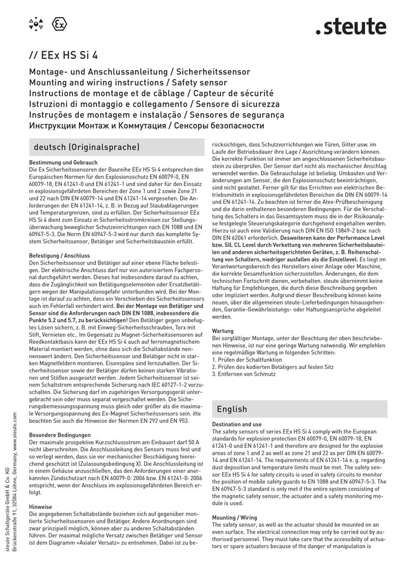
CGEO-TEM2
Resistance Temperature Sensor
Installation Manual
(REV A)

Contents
1. Brief Introduction.................................................................................................................. 1
2. Main Specifications .............................................................................................................. 1
3. Cable Welding Lengthening................................................................................................. 2
4. Using Surroundings & Installation Notice............................................................................3
5. Operation & Data Process..................................................................................................... 3
6. Temperature Calculation Formula........................................................................................4
7. Trouble Shooting .................................................................................................................. 5

CGEO-TEM2 Resistance Temperature Sensor 1
1. Brief Introduction
CGEO-TEM2 Thermometer is composed of a stainless steel crust, thermo-resistance, and
the CGEO-4-SCT special cable with the outstanding water-proof capability and signal
stability. It is widely used in temperature controlling and monitoring of high technology,
industrial production and science research and other areas. The temperature of the measured
environment can be read out directly by CGEO-PR-VW Readout .
Cable
Stainless steel crust and transducer
Structure of CGEO-TEM2 Temperature Gauge
The features of CGEO-TEM2 Temperature Gauge as follows:
•Good long-time stability
•Stainless steel structure, which is adaptable to all kinds of atrocious environment
•Good water-proof capability
•Long working life
•High sensitivity
•Applicable to the measuring of the temperature of liquid, solid or gas in the non-strong-acid,
non-strong-alkali or non-strong-corrosive environment.
2. Main Specifications
•Temperature Range: -30℃~+70℃
• Accuracy: standard ±0.5℃(Option:±0.2℃,±0.1℃)
• Resistance in normal temperature: 3KΩ(At 25℃)
• Insulated resistance: ≥50MΩ
• withstanding voltage: 1500V
• Outer Size: Φ11×110mm
•Color of the lead of cable: green/white (temperature transducer), shield (grounded)

BSIL-T2-1.1 Instruction Manual
CGEO INTERNATIONAL LIMITED Installation Manual
2
3. Cable Welding Lengthening
A standard CGEO-TEM2 model temperature gauge equips with 1m cable in ex-factory,
cable model is CGEO-4-SCT. For cable lengthening adopted is CGEO-4-SCT dedicated cable,
and BSIL-4-SC cable as well as. Proceed lengthening basing on the field circumstance before
installation. Avoid connection as possible as in the cable buried in soil. If cable connection is
inevitable, should adopt waterproof connection, recommend using ES-3 model dedicated
heat-shrinkable connector, and also epoxy connector, like 3M ScotchcastTM 82-A1 dedicated
cable connector, those connector devices can be ordered from Beijing SOIL.
As following details introduction of connection method of using ES-3 model dedicated
heat-shrinkable connector.
Measure the resistance between cores of transducer with millimeter and note it before
welding. Thereinto, the resistance between green and white core should be 3kat room
temperature 25℃. As to CGEO-TEM2 model temperature gauge, the resistance between red
and black core leads is the same as green and white.
Before welding divest the outer leather of cable end part, length about 8cm, and expose
the core leads, roughen rest cable outer leather part with emery cloth or sandpaper, length
about 3 cm. Sleeve φ12mm heat-shrinkable tube onto outside cable (length about 14cm).
Strip outer skin of cores 0.5~0.8 cm with stripping pliers, jacket φ2mm heat-shrinkable tube
onto core leads. After twisting core leads together corresponding to colors, solder tin with
electric soldering iron. Should avoid poor soldering and remove burrs during soldering
process. 5 pieces of cores all are needed to solder, please note: 1). Stagger each core
connector; 2). Ensure every core lead length same and ensure each core uniformly forced
when cable is pulled. After soldering, naked core line length about 7 cm, push φ2mm outer
heat-shrinkable tube onto core leads connector part, and make it shrunk in connector part with
heat wind gun. At last push φ12mm heat-shrinkable tube unto cable connector and heat-
shrunk in connector part with heat wind gun. φ12mm heat-shrinkable tube should be
pressed 3 cm over each end of cable outer skin. Should control the temperature when using
heat-wind gun so that heat-shrinkable tube internal in transparent, fluid status, and fully filled
with connector internal. But too high temperature will melt core lead outer skin and cause

BSIL-T2-1.1 Instruction Manual
CGEO INTERNATIONAL LIMITED Installation Manual
3
core lead short, cause heat-shrinkable tube carbonization and brittle.
Note: after core leads welding work finishing, you must check the reading
measurement with readout, and examine the resistance between cores of cable with
millimeter in case welding work causes connector part short and cut
Figure 5 Cable welding splice diagram
4. Using Surroundings & Installation Notice
Though the CGEO-TEM2 Temperature Transducer can be used in all atrocious
environments, it is still necessary to avoid using in the area which is over the standard range
(with the exception of the customized), and avoid long-time using in strong acid and alkaline
areas.
The CGEO-TEM2 Temperature Transducer can be installed directly inside concrete, soil
or borehole. But what is needed to do is to protect the cable and meet all the standard
requirements.
5. Operation & Data Process
The signal cable of CGEO-TEM2 Temperature Gauge adopts 4-core shielded cable,
the colors of cable core wires are Black, Red, Green, and White respectively and another
naked wire is shield wire to ground. Among them, red and white are in parallel connected, so
do green and Black, when measuring, you can connect at discretion black, red core wires or
green, white core wires. You also can twist together red, white core wires or green, black core
wires of temperature gauge and then connect with green, white wires of readout box to
measure.
φ12mm heat-shrinkable tube
热缩套管
Cable outer skin
φ2mm heat-shrinkable tube
Core connector
Transducer core leads

BSIL-T2-1.1 Instruction Manual
CGEO INTERNATIONAL LIMITED Installation Manual
4
Red
Red
红
Whit
e白
Gree
n绿
Blac
Readout
Box
读数仪
Gree
n绿
Whit
e白
CGEO-TEM2 thermometer wiring schematic diagram
When measuring, connect the green and white nips of CGEO-PR-VW to the black, red wires
of the transducers to read out directly, or connect green, white nips to black, red wire of
thermometer, and then the thermistor readings can be displayed directly in C.
Note,please do not connect 4 colors nips of readout box to 4 core wires of thermometer
simultaneously, that is, it is just allowed to connect two wires every time to measure
temperature, otherwise it will result in readings error.
There are no polarity difference in signal lines of CGEO-TEM2 thermometer, green,
white wire are changeable.
6. Temperature Calculation Formula
TA B LnR C LnR
1273 2
3
( ) ( ) .
where:
T
Temperature in
C.
R
Resistance of the temperature transducers inΩ.
LnR
Natural Log of Thermistor Resistance
A
1.4051
10-3 (coefficient is effective in range -50℃~+150℃)
B
2.369
10-4
C
1.019
10-7
If there is no special readout, the thermistor can be read by using a digital ohmmeter in
conjunction with the above equation, or get the temperature by Appendix A.

BSIL-T2-1.1 Instruction Manual
CGEO INTERNATIONAL LIMITED Installation Manual
5
7. Trouble Shooting
When troubles occur, a millimeter is usually used to check core wire resistance and examine
the breakdown phenomena.
When checking, connect the digital millimeter to the cores of the transducer, the normal
condition is that the resistance matches the environment temperature (check Appendix A). In
25
C, the resistance should be 3000Ω. If the resistance deviates from the norms, it is caused
normally by cable open or short, should focus on inspecting the cable for damage.
If the cable is damaged or affected with damp, the reading will be fuzzy, a bit bigger than the
correct reading. What should be noticed is that, if the cable is too long and under the
high-temperature environment, the resistance of cable core should be taken into consideration
during calculating, to gain a higher precision. This resistance will not be taken into
consideration under low-temperature environment. The resistance of matched cable core is
about 50Ω/1000m, and doubled when in two-direction.
Appendix A: Resistance versus Temperature Table

BSIL-T2-1.1 Instruction Manual
CGEO INTERNATIONAL LIMITED Installation Manual
6
Ohms
Temp
Ohms
Temp
Ohms
Temp
Ohms
Temp
Ohms
Temp
201.1K
-50
16.60K
-10
2417
30
525.4
70
153.2
110
187.3K
-49
15.72K
-9
2317
31
507.8
71
149.0
111
174.5K
-48
14.90K
-8
2221
32
490.9
72
145.0
112
162.7K
-47
14.12K
-7
2130
33
474.7
73
141.1
113
151.7K
-46
13.39K
-6
2042
34
459.0
74
137.2
114
141.6K
-45
12.70K
-5
1959
35
444.0
75
133.6
115
132.2K
-44
12.05K
-4
1880
36
429.5
76
130.0
116
123.5K
-43
11.44K
-3
1805
37
415.6
77
126.5
117
115.4K
-42
10.86K
-2
1733
38
402.2
78
123.2
118
107.9K
-41
10.31K
-1
1664
39
389.3
79
119.9
119
101.0K
-40
9796
0
1598
40
376.9
80
116.8
120
94.48K
-39
9310
1
1535
41
364.9
81
113.8
121
88.46K
-38
8851
2
1475
42
353.4
82
110.8
122
82.87K
-37
8417
3
1418
43
342.2
83
107.9
123
77.66K
-36
8006
4
1363
44
331.5
84
105.2
124
72.81K
-35
7618
5
1310
45
321.2
85
102.5
125
68.30K
-34
7252
6
1260
46
311.3
86
99.9
126
64.09K
-33
6905
7
1212
47
301.7
87
97.3
127
60.17K
-32
6576
8
1167
48
292.4
88
94.9
128
56.51K
-31
6265
9
1123
49
283.5
89
92.5
129
53.10K
-30
5971
10
1081
50
274.9
90
90.2
130
49.91K
-29
5692
11
1040
51
266.6
91
87.9
131
46.94K
-28
5427
12
1002
52
258.6
92
85.7
132
44.16K
-27
5177
13
965.0
53
250.9
93
83.6
133
41.56K
-26
4939
14
929.6
54
243.4
94
81.6
134
39.13K
-25
4714
15
895.8
55
236.2
95
79.6
135
36.86K
-24
4500
16
863.3
56
229.3
96
77.6
136
34.73K
-23
4297
17
832.2
57
222.6
97
75.8
137
32.74K
-22
4105
18
802.3
58
216.1
98
73.9
138
30.87K
-21
3922
19
773.7
59
209.8
99
72.2
139
29.13K
-20
3748
20
746.3
60
203.8
100
70.4
140
27.49K
-19
3583
21
719.9
61
197.9
101
68.8
141
25.95K
-18
3426
22
694.7
62
192.2
102
67.1
142
24.51K
-17
3277
23
670.4
63
186.8
103
65.5
143
23.16K
-16
3135
24
647.1
64
181.5
104
64.0
144
21.89K
-15
3000
25
624.7
65
176.4
105
62.5
145
20.70K
-14
2872
26
603.3
66
171.4
106
61.1
146
19.58K
-13
2750
27
582.6
67
166.7
107
59.6
147
18.52K
-12
2633
28
562.8
68
162.0
108
58.3
148
17.53K
-11
2523
29
543.7
69
157.6
109
56.8
149
55.6
150

BSIL-T2-1.1 Instruction Manual
CGEO INTERNATIONAL LIMITED Installation Manual
7
CGEO-TEM2 Semiconductor Thermometer Control Table of Resistance - Temperature
Table of contents
Popular Accessories manuals by other brands
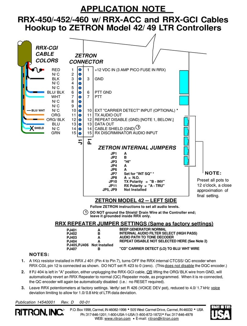
Ritron
Ritron RRX-450 Application note

Crivit
Crivit 322422 1901 Instructions for use
IFM Electronic
IFM Electronic O5E5 A Series operating instructions
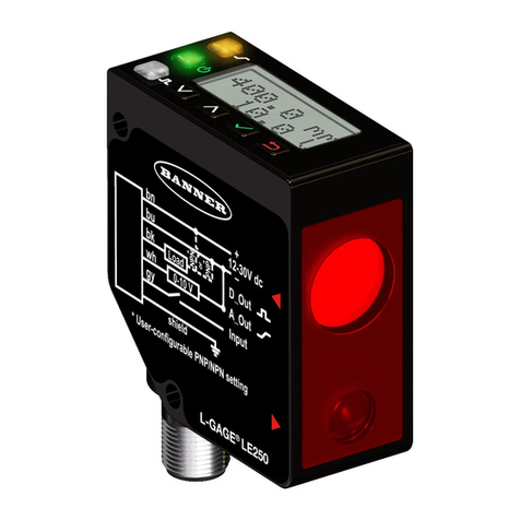
Banner
Banner L-GAGE LE250 IO-Link instruction manual
TVILIGHT
TVILIGHT CitySense Plus installation manual

PCB Piezotronics
PCB Piezotronics 353B01 Installation and operating manual
