nekos NRS1 User manual
4420068 – Rev. 1801
NRS1 – NRS1/R
INSTRUCTION MANUAL
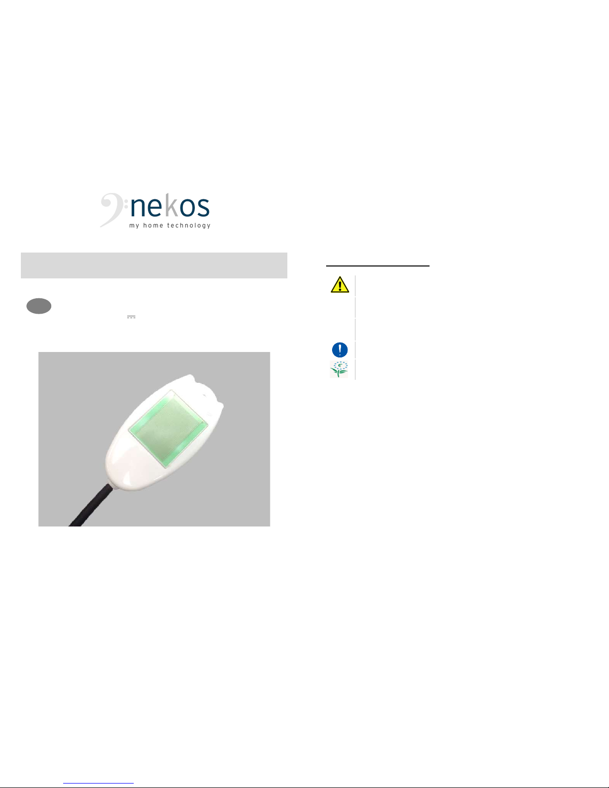
HEATED RAIN SENSOR
Electrical feeding 24V
E
N
2
nekos products have been manufactured in accordance with safety standards and conforms to
the stipulations of current standards in force.
When correctly assembled, installed and used according to the present instructions, they will not
generate any danger for persons, animals or items.
Symbols used in the manual
DANGER This indication draw the attention about potential dangers for
safety and health of peoples and animals.
INFORMATION This information give further suggestions.
ATTENTION This indication draw the attention about potential dangers for
the product itself.
WARNING This indication draw the attention about potential damages to
goods.
ENVIRONMENTAL
INSTRUCTION
Environmental indication draw the attention about potential
dangers for the environment.
Contents
1. Safety indications ............................................................................................... 3
1.1. General notes .......................................................................................... 3
1.2. Notes for functioning and use .................................................................. 3
2. Technical and constructional information ........................................................... 4
3. Technical data .................................................................................................... 4
4. Id plate and marking data ................................................................................... 4
5. Technical information ......................................................................................... 4
6. Advices and instruction for mounting .................................................................. 5
7. Electrical connections ......................................................................................... 5
7.1. Replace P2 rain sensor on N series units ................................................ 6
8. Dip-switches selection ........................................................................................ 6
9. Led signals ......................................................................................................... 6
10. Radio control for closing due to rain (NRS1R) .................................................... 6
10.1. Saving the rain sensor on KATO ADV RADIO ......................................... 7
11. Environmental protection .................................................................................... 7
12. Recall to main principles of warranty certificate .................................................. 7
13. Declaration of conformity .................................................................................... 8

3
1. SAFETY INDICATIONS
1.1. General notes
WARNING: BEFORE INSTALLING THIS APPLIANCE, ENSURE ALL SAFETY INDICATIONS
HAVE BEEN READ CAREFULLY AND UNDERSTOOD IN ORDER TO PREVENT CONTACT WITH
ELECTRICITY, INJURY OR ANY OTHER INCIDENT. THE MANUAL SHOULD BE CONSERVED
FOR FURTHER CONSULTATION AT A LATER DATE.
The manufacturer accepts no responsibility for damage to people, animals
or things incurred by improper use.
Use for any applications other than those indicated must be authorised by
the manufacturer after technical review of the assembly.
Plastic bags, polystyrene, small metal parts such as nails, staples etc. should be
placed out of the reach of children as they constitute a potential source of risk.
The appliance is not intended for use by people (including children) whose
physical, sensory and mental abilities are reduced, or in case of lack of
experience or knowledge; such persons must be supervised to ensure that they
do not play with the appliance.
Do not use solvents or jets of water to wash the appliance. The appliance should
not be submerged in water.
1.2. Notes for functioning and use
NRS1-NRS1/R (NRS1R is different from the other because of the antenna protected by a
black sheath in the feeding cable) is a sensor to detect rain and through the connected
cable or in case of R version by means of a 433,92 MHz radio signal, transmits the signal to
a device able to interpret it.
Use for any applications other than those indicated must be authorised by the
manufacturer after technical review of the assembly.
This product is designed to be used with the manufacturer's original products.
Use with any other products may result in damage or malfunctions.
The initial start-up of the sensor should be carried out by a skilled and qualified
person following the manufacturer's instructions.
After removing packaging, check for any damage on the appliance.
Before using the rain sensor, check that the power has the same nature, quality
and tension as those indicated on the technical data label on the appliance.
This machine is destined exclusively for the use for which it has been designed
and the manufacturer accepts no responsibility for damage incurred by improper
use.
Repairs should only be performed by qualified personnel at assistance centres
authorised by the manufacturer.
The product must be disposed of in compliance with local environmental
regulations and not as household waste.
4
2. TECHNICAL AND CONSTRUCTIONAL INFORMATION
NRS1 and NRS1/R sensors signal the rain event to an apparatus able to interpret and
command the connected devices. The sensor is insensitive to the formation of dew or
moisture after rainfall dries very quickly and being heated - below +5 °C - does not
allow the formation of ice.
The sensor is fed with a tension between 12V and 24V .
Electrical connection must comply with the rules in force on electrical systems.
All connected devices must be manufactured according to the regulations in force and
comply with regulations issued by the European Community.
3. TECHNICAL DATA
Model
NRS1
Power supply voltage 12V ÷ 24V
Maximum absorbed power 20 mA (120 mA with active heater)
Type of sensor Capacitive
Heater intervention < +5 °C
Type of contact SPDT
Rating contact 0,5 A / 125V~ – 1 A / 24V
RF transmission 433,92 MHz
Functioning temperature -20 ÷ +65 °C
Operating radius in open air 50 m
Feeding cable length 5 m
Feeding cable type / number of wires PVC LiY2Y protected from UV / 5 wires
Protection index IP65
Dimensions 45x93 h=19 mm
Weight
52 g (cable excluded)
Any data reported in this table is not binding and may be susceptible to variations without notice.
4. ID PLATE AND MARKING DATA
NRS1 and NRS1/R rain sensors have marking and are destined for use in the
European Union without further requirements.
ID plate data are indicated on a polyethylene adhesive label applied on the product,
printed in black on a grey background.
5. TECHNICAL INFORMATION
NRS1 or NRS1/R rain sensor, to completely fulfil its task, has to be placed out in the open
fully exposed to any precipitation, possibly over the roof or in a similar position, or where
can be affected by rainfall.
Sensor can be connected to all stations or devices where signal processing is foreseen or
where a free contact signal is necessary (free from tension).
Feeding cable is 5 m long, made weather resistant, fire retardant and UV resistant.

5
6. ADVICES AND INSTRUCTION FOR MOUNTING
THESE INSTRUCTIONS ARE INTENDED FOR TECHNICAL AND SPECIALIZED PERSONNEL.
THUS BASIC SAFETY AND WORKING TECHNIQUES ARE NOT DISCUSSED.
To guarantee perfect function and facilitate installation, please note the following
indications and warnings:
Check that the cable length is sufficient to link to the station or control apparatus.
The eventual junction for extending the cable must be perfectly sealed with a
cable of the same type and colours.
Warning
.
Check that the power supply is the same as those indicated on
technical data applied to the device.
To keep efficient and have a perfect functioning we suggest to clean the sensitive
part at least any 6 months or any time is dirty due to smog, leaves, impurity, etc.
Advices for sensor installation:
1. Choose the most suitable position where place the rain sensor. It has to be put outside
in direct contact with weathering.
2. The sensor is placed slightly tilted (~ 20 °) to facilitate the flow of water, in a position
that does not have shelters to the fall of rain. Place it under the trees is not
recommended because it alters the natural weather event.
3. Support can be of 2 types depending from attack surface; in both cases is suggested
to make the cable exit below:
o Surface flat / tilted – with high resistance adhesive and suitable for weather or
fixed with a screw;
o Fix support such as rod or similar where to apply the metal bracket – provided –
with a screw.
4. Complete cable system and electrical connection to the station or control and feeding
apparatus following the schema on next page. Bind with one or more clamps the cable
to make it integral with the supporting structure.
5. If radio version is used, check rain sensor memorization has been done on control
device (Kato ADV Radio).
6. Make a functional test.
To test a rain sensor is sufficient to wet (pour or spray water) on sensitive
part of it; the sensor transmits the signal of “wet sensor”. LED indicators of
various apparatus should light.
7. ELECTRICAL CONNECTIONS
Electrical connections should be carried out in compliance with safety rules and
keeping in mind the meaning of various symbols and colours of the wires of the
feeding cable.
Sensor can work with any station unit or apparatus able to interpret its signal,
therefore the connections of the power cord are called in the specific instructions
of the central or equipment.
The table below shows the caption of any wires and the wiring diagram.
6
Caption of each wire - NRS1:
1 - R
ED
(+) connected to +12/24V;
2 - B
LACK
(-) connected to -12/24V;
3 - B
LUE
(N.O. contact);
4 - P
URPLE
(N.C. contact);
5 - G
REEN
(Common).
Caption of each wire - NRS1/R:
1 - R
ED
(+) connected to +12/24V;
2 - B
LACK
(-) connected to -12/0V;
3 - B
LUE
DON’T CONNECT;
4 - P
URPLE
DON’T CONNECT;
5 - G
REEN
DON’T CONNECT.
7.1. Replace P2 rain sensor on N series units
In the case of useNRS1 rain sensor to replace the old P2 on N series stations,
during connection phase operate as follows:
RED wire connected at the place of WHITE wire;
BLACK and GREEN wires connected together at the place of YELLOW wire;
BLUE wire connected at the place of BLUE wire;
PURPLE wire has to be insulated and not connected.
8. DIP-SWITCHES SELECTION
In the sensor base, covered by a black cap, there is the access to dip-switches to
program the sensor which give the possibility of modifying status and sensitiveness. Dip-
switches meaning is the following:
DIP 1 DIP2 SENSITIVENESS
OFF OFF Maximum sensitiveness
ON OFF Medium-high sensitiveness
OFF ON Medium-low sensitiveness
ON ON Minimum sensitiveness
The sensor leaves the factory with the maximum sensitiveness set.
9. LED SIGNALS
Rain sensor has 2 signalling LED that indicate the functioning status.
B - BLUE led flashing indicates that the sensor is fed.
R - RED led lit fix indicates “wet sensor”; it has active command.
10. RADIO CONTROL FOR CLOSING DUE TO RAIN (NRS1R)
The NRS1R radio rain sensor is a device capable of controlling the KATO ADV RADIO
motor remotely through a 433.92MHz signal.

7
THE RAIN SENSOR IS NOT FACTORY-PROGRAMMED (ASSOCIATED).
First follow the instructions provided below concerning the specific operation of the machines
you would like to control, then those of the actuator to be controlled (KATO ADV RADIO).
10.1. Saving the rain sensor on KATO ADV RADIO
The NRS1R rain sensor, as soon as it senses the presence of rain, transmits a unique signal
at the radio frequency 433.92 MHz. The NRS1R rain sensor can be used to control several
actuators, as long as the sensor is associated with the various KATO ADV RADIO actuators
and thus a window, with the procedure described below.
The encoding used varies for each channel, so each transmission will send a signal that is different
from all the others. It follows that the receiver must be able to recognize the enabled transmitters,
thus the transmission codes should be saved following the procedure below:
Equip yourself with the NRS1R radio rain sensor, checking beforehand that it is working
and is powered properly (Blue LED flashing).
On the KATO ADV RADIO actuator, briefly press (for about 1 second) the small “PRG”
button located near the terminal block. The slowly flashing LED indicates that it is waiting
to receive a valid radio code.
Within 10 seconds, place the palm of your hand on the rain sensor (on the grey circular
zone) waiting for the Red LED rain indicator to start flashing.
If the code is saved correctly, the LED on the KATO ADV RADIO actuator will emit one
long flash (1 sec.) as confirmation; then the LED will go out and remain at rest.
If the code is not saved correctly - due to the memory being full, for example, or the
sensor being incompatible - the LED on the KATO ADV RADIO actuator will emit a series
of quick flashes for about 1 second; then the LED will go out and remain at rest.
11. ENVIRONMENTAL PROTECTION
All materials used in the manufacture of this appliance are recyclable.
We recommend that the device itself, and any accessories, packaging, etc. be sent to a
centre for ecological recycling as established from laws in force on recycling.
The device is mainly made from the following materials:
Iron Aluminium Cuprum Zinc Silicon Plastic of various type
Dispose materials in conformity with local regulations about removal.
12. RECALL TO MAIN PRINCIPLES OF WARRANTY CERTIFICATE
The manufacturer will guarantee good function of the appliance. The manufacturer shall
undertake to replace defective parts due to poor quality materials or manufacturing defects. The
guarantee covers products and individual parts for 2 years from the date of purchase. The latter
is valid as long as the purchaser possesses proof of purchase and completion of all agreed
conditions of payment. Guarantee of good function of appliances agreed by the manufacturer
implies that the latter undertakes to repair or replace free of charge and in the shortest period
possible any parts that break while under warranty. The purchaser is not entitled to any
reimbursement for eventual direct or indirect damage or other expenses incurred. Attempt to
repair by personnel unauthorised by the manufacture shall render the warranty null and invalid.
The warranty does not cover fragile parts or parts subject to natural wear and tear or corrosion,
overload, however temporary etc. The manufacturer will accept no responsibility for eventual
damage incurred by erroneous assembly, manoeuvre or insertion, excessive stress or inexpert
use. Repairs performed under guarantee are always "ex-factory of the manufacturer".
Respective transport expenses (out/back) are the responsibility of the purchaser.
8
13. DECLARATION OF CONFORMITY
The undersigned,
Company name: NEKOS S.r.l
Postal address: Via Capitoni, 7/5
Postcode and city:
36064 Mason Vicentino VI
Telephone number: +39 0424 411011
E-mail address: [email protected]
declare that the document is issued under our sole responsibility and belongs to the following product:
Apparatus model / Product: Heated rain sensor NRS1 – NRS1/R
Trademark: NEKOS
Model/Type: NRS1 – NRS1/R
Batch: see data label
Serial number: see data label
The object of the declaration described above is in conformity with the relevant Union harmonisation legislation:
2014/30/EU ElectroMagnetic Compatibility Directive (EMCD)
2014/35/EU Low Voltage Directive (LVD)
2014/53/EU Radio Equipment (RED)
2011/65/EU Restriction of the use of certain hazardous substances Directive (RoHS Directive)
The following harmonised standards and/or technical specifications have been applied:
EMC:
EN 61000-6-3:2007 + A1:2011
EN 61000-6-2:2005 + AC:2005
LVD
EN 60335-1:2012 + EN 60335-1/A11:2014
RED
ETSI EN 300 220-1 V3.1.1 – ETSI EN 300 220-2 V3.1.1
ETSI EN 301 489-1 V2.1.1 – ETSI EN 301 489-3 V2.1.1
RoHS
EN 50581:2012
Place: Mason Vicentino
Date: 13/06/2017
Signature: Giuliano Galliazzo (A.D. – President)
NEKOS S.r.l. - Via Capitoni, 7/5
36064 Mason Vicentino (VI) – ITALY
+39 0424 411011 – +39 0424 411013
This manual suits for next models
1
Table of contents
Other nekos Accessories manuals


