O.S. Speed 12xz Spec II User manual

It is of vital importance, before attempting to operate your
engine, to read the general 'SAFETY INSTRUCTIONS
AND WARNINGS' section on pages 2-5 of this booklet
and to strictly adhere to the advice contained therein.
Also, please study the entire contents of this instruction
manual, so as to familiarize yourself with the controls
and other features of the engine.
Keep these instructions in a safe place so that you may
readily refer to them whenever necessary.
It is suggested that any instructions supplied with the
vehicle, radio control equipment, etc., are accessible for
checking at the same time.
1
CONTENTS
SAFETY INSTRUCTIONS AND
WARNINGS ABOUT YOUR O.S. ENGINE
ENGINE CONSTRUCTION, NOTES WHEN
APPLYING AN ELECTRIC STARTER
ABOUT THE WARRANTY
ABOUT THE ENGINE
TOOLS, ACCESSORIES, etc.
BASIC ENGINE PARTS
INSTALLATION OF THE STANDARD
ACCESSORIES, GLOWPLUG
INSTALLATION ,
CARBURETOR CONTROLS 12F(B)
2-5
6-7
8-9
13-14
15-17
18-22
STARTING THE ENGINE & RUNNING-IN
('Breaking-in)
FINAL ADJUSTMENT
CARE AND MAINTENANCE
TROUBLE SHOOTING
ENGINE EXPLODED VIEW &PARTS LIST
CARBURETOR EXPLODED VIEW &PARTS LIST
O.S. GENUINE PARTS & ACCESSORIES
THREE VIEW DRAWING
36-37
10-12
38
26-27
28-31
32-33
23-25
34-35

2
!
!
Remember that your engine is not a "toy", but a highly efficient internal-
combustion machine whose power is capable of harming you, or others, if it is
misused.
As owner, you, alone, are responsible for the safe operation of your engine, so act
with discretion and care at all times.
If at some future date, your O.S. engine is acquired by another person, we would
respectfully request that these instructions are also passed on to its new owner.
SAFETY INSTRUCTIONS AND WARNINGS ABOUT YOUR O.S. ENGINE
The advice which follows applies basically to ALL MODEL ENGINES and is
grouped under two headings according to the degree of damage or danger
which might arise through misuse or neglect.
WARNINGS NOTES
These cover events which
might involve serious (in
extreme circumstances, even
fatal) injury.
These cover the many other
possibilities, generally less obvious
sources of danger, but which, under
certain circumstances, may also
cause damage or injury.
3
!
WARNINGS
Model engine fuel is poi-
sonous. Do not allow it to
come into contact with the
eyesormouth.Alwaysstore
it in a clearly marked con-
tainer and out of the reach
of children.
Model engine fuel is also
highly flammable. Keep it
away from an open flame,
excessive heat, sources of
sparks, or anything else
which might ignite it. Do not
smoke or allow anyone else
to smoke, near to it.
Never operate your engine in an en-
closed space. Model engines, like
automobile engines, exhaust deadly
carbon-monoxide. Run your engine
only in an open area.
Model engines generate
considerable heat. Do not
touch any part of your
engine until it has cooled.
Contact with the muffler
(silencer), cylinder head
or exhaust header pipe, in
particular, may result in a
serious burn.
••
•
•

4
!
This engine is intended for model cars.
Do not attempt to use it for any other
purpose.
Mount the engine in your model
securely, following the manufacturers'
recommendations, using appropriate
screws and locknuts.
Install an effective silencer (muffler).
Frequent close exposure to a noisy
exhaust (especially in the case of the
more powerful highspeed engines)
may eventually impair your hearing
and such noise is also likely to cause
annoyance to others over a wide area.
The wearing of safety glasses is also
strongly recommended.
Take care that the glowplug clip or
battery leads do not come into contact
with rotating parts. Also check that the
linkage to the throttle arm is secure.
For their safety, keep all onlookers
(especially small children) well back
(at least 20 feet or 6 meters) when
preparing your model for running.
NOTES
•
•
•
•
•
•
5
!
NOTES
To stop the engine, fully retard the
throttle stick and trim lever on the
transmitter, or, in an emergency, cut
off the fuel supply by pinching the fuel
delivery line from the tank.
•
Warning! Immediately after a glowplug-
ignition engine has been run and is still
warm, conditions sometimes exist
whereby it is just possible for the engine
to abruptly restart if it is rotated over
compression WITHOUT the glowplug
battery being reconnected.
•
Before starting the engine, always check
the tightness of all the screws and nuts
especially those of joint and movable
parts such as throttle arm. Missing
retightening the loose screws and nuts
often causes the parts breakage that is
capable of harming you.

6
Piston
Cylinder Liner
Crankshaft
ENGINE CONSTRUCTION
With this engine, the piston will
feel tight at the top of its stroke
(TDC) when the engine is cold.
This is normal. The cylinder bore
has a slight taper. The piston
and cylinder are designed to
achieve a perfect running
clearance when they reach
operating temperature.
Near TDC
Slight taper
When the engine is cold. When the engine is hot.
7
NOTES WHEN APPLYING
AN ELECTRIC STARTER
Do not over-prime. This could
cause a hydraulic lock and damage
the engine on application of the
electric starter.
If over-primed, remove glowplug,
close needle-valve and apply
starter to pump out surplus fuel.
Cover the head with a rag to
prevent any pumped out fuel from
getting into your eyes.

8
As delivered, the engine has the
carburetor lightly fit into its intake.
Secure it changing its angle
according to the car chassis.
NOTE
ABOUT THE WARRANTY
Since this is a special
factory tuned engine,
special parts are available
for only limited time, say,
one year after discontinuing
the production.
Also, the engine is free of
warranty due to damage
and/or wear occurred during
running.
9
Standard accessories
Glow Plug RP6 T-type head (Turbo head)
1piece
Exhaust Seal Ring 1piece
ABOUT THE ENGINE
The O.S. SPEED 12XZspec is a
high performance engine meeting
IFMAR specification produced by
O.S.’s SPEED TEAM technicians.
Major parts such as cylinder &
piston assembly, crankshaft and
crankcase are have been refined to
have a powerful potential equal to
more expensive specially tuned or
modified engines. Also, it employs
a outer head that has many drilled
holes for lighter weight and better
cooling, and a ceramic rear ball
bearing for lower friction loss.
Dust Cap Set
3mm 1piece 16mm 2pcs.

10
GLOWPLUG IGNITER
Commercialy available handy
glowplug heater in which the
glowplug battery and battery
leads are integrated.
FUEL
Generally, it is suggested that the user selects a fuel
that is commercially available for model two-stroke
engines and contains 10-30% nitromethane. As a
starting point, we recommend a fuel containing 20%
nitromethane, changing to a fuel containing more
nitro if necessary. When the brand of fuel is changed,
or the nitro content increased, it is advisable to
repeat the running-in procedure referred to in the
RUNNING-IN paragraphs. Please note that with
high-nitro fuels, although power may
be increased for competition purposes,
glowplug elements do not last as long
and engine life will be shortened.
Items necessary for starting
!
REMINDER!
Model engine fuel is poisonous. Do not
allow it to come into contact with the
eyes or mouth. Always store it in a
clearly marked container and out of the
reach of children.
TOOLS, ACCESSORIES, etc.
The following items are necessary for operating the engine.
!
Model engine fuel is also highly
flammable. Keep it away from open
flame, excessive heat, sources of sparks,
or anything else which might ignite it. Do
not smoke or allow anyone else to
smoke, near to it.
FUEL FILTER
To be installed in the fuel line
between fuel tank and carburetor
to prevent foreign matter from
entering the carburetor.
STARTER BOX
For starting the engine.
11
FUEL PUMP
For filling the fuel tank, a simple,
polyethylene "squeeze" bottle,
with a suitable spout, is required.
SILICONE FUEL LINE
Heatproof silicone tubing of
approx. 5mm o.d. and 2mm i.d. is
required for the connection
between the fuel tank and engine.
TOOLS
HEX SCREWDRIVER
SCREWDRIVER
Necessary for engine installation.
1.5mm, 2mm, 2.5mm, 3mm
Necessary for carburetor adjustments.
No.1, No.2, etc
LONG SOCKET WRENCH WITH PLUG GRIP
Recommended for easy removal and
replacement of the angled and recessed
glowplug, the O.S.Long Socket Wrench
incorporates a special grip.
BATTERIES FOR STARTER BOX
Batteries for starter box.Select
according to the starter box
used. Be sure to fully charge
before using.

12
BASIC ENGINE PARTS
Outer Head
Crankcase
Mounting Lugs
Exhaust
Cover Plate
Carburetor
Type 12F(B)
Crankshaft
Crankshaft Ball Bearing (Front)
13
INSTALLATION OF THE STANDARD ACCESSORIES
Install the exhaust seal
ring supplied.
Exhaust
Seal Ring
Glowplug
Installing the glow plug.
Insert RP6 plug supplied
into heatsink-head care-
fully, making sure that it is
not cross-threaded before
tightening firmly.
(All the O.S. T-Type plugs
including the RP6 are not
supplied with a washer.)
About the Head Gasket
These engines are equipped with two head
gaskets of 0.1mm thick and 0.2mm thick. It
is suggested to adjust the total thickness
according to atmospheric temperature,
humidity and glowplug used.
At early stage of running-in, when a
glowplug tends to burn out early or when
high nitromethane content fuel is used, try
to run the engine with both gaskets or
removing the 0.1mm gasket.
When low nitromethane content fuel is
used, try to run the engine removing the
0. 2mm gasket.
INSTALLATION OF THE DUST CAP SET
If the engine is to be stored or out of use for a while,
install the included exhaust and carburetor dust caps
to prevent foreign matter from entering the engine.

14
GLOWPLUG
The role of the glowplug
Glowplug life
Particularly in the case of very high performance
engines,
glowplugs must be regarded as expendable
items. However, plug life can be extended and engine
performance maintained by careful use, i.e.:
Install a plug suitable for the engine.
Use fuel containing a moderate percentage of
nitromethane unless more is essential for racing events.
Do not run the engine too lean and do not leave the
battery connected while adjusting the needle.
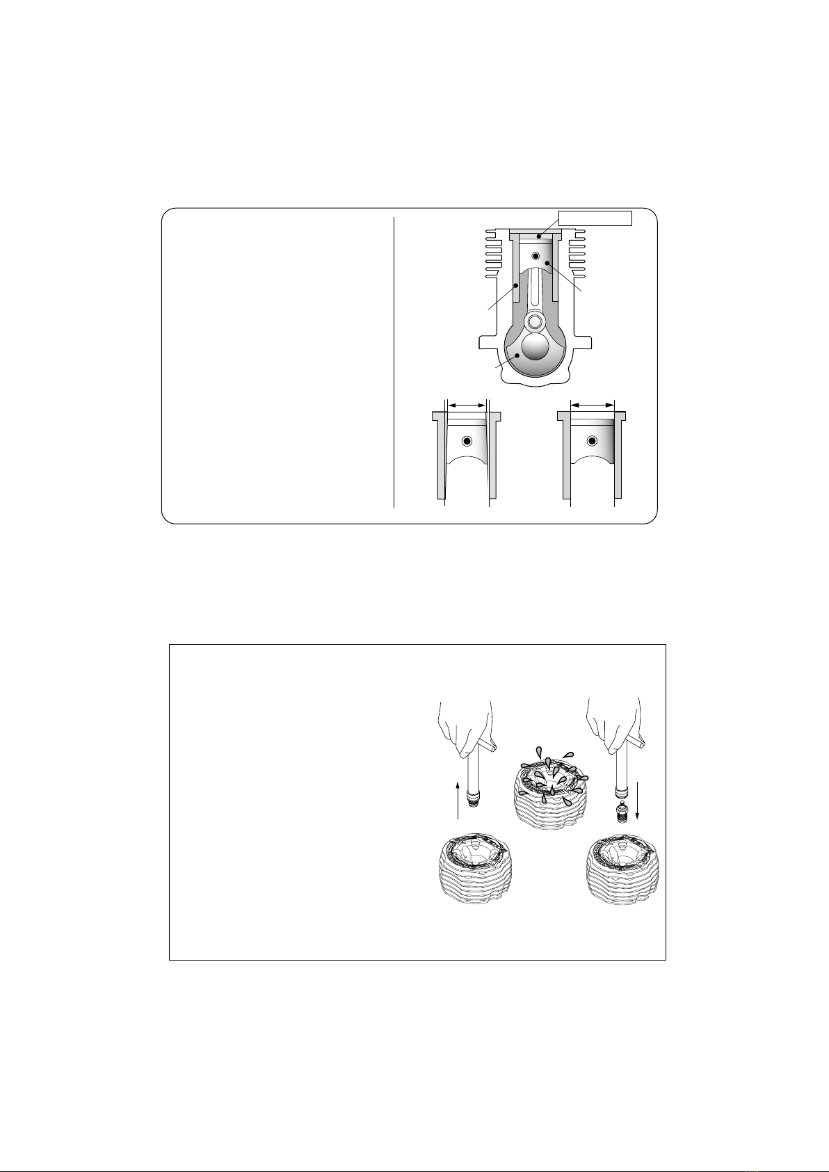
With a glowplug engine, ignition is initiated by the
application of a 1.5-volt power source. When the
battery is disconnected, the heat retained within the
combustion chamber remains sufficient to keep the
plug filament glowing, thereby continuing to keep the
engine running. Ignition timing is 'automatic' : under
reduced load, allowing higher rpm, the plug becomes
hotter and, appropriately, fires the fuel/air charge
earlier; conversely, at reduced rpm, the plug become
cooler and ignition is retarded.
Apart from when actually burned out, a plug may
need to be replaced because it no longer delivers its
best performance, such as when:
When to replace the glowplug
Filament surface has roughened and turned white.
Filament coil has become distorted.
Foreign matter has adhered to filament or plug
body has corroded.
Engine tends to cut out when idling.
Starting qualities deteriorate.
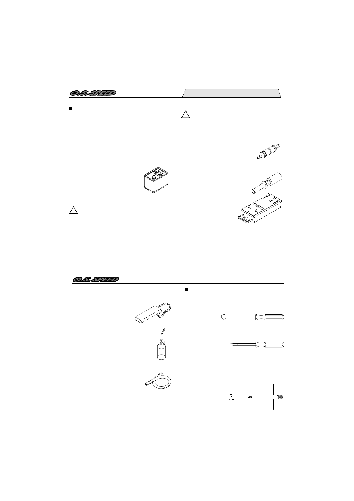
Since the compatibility of the glowplug
and fuel may have a marked effect on
performance and reliability, it is suggested
to use the O.S. RP6 plug when it is
necessary to replace. Carefully install
plug finger-tight, before final tightening
with the correct size plug wrench.
15
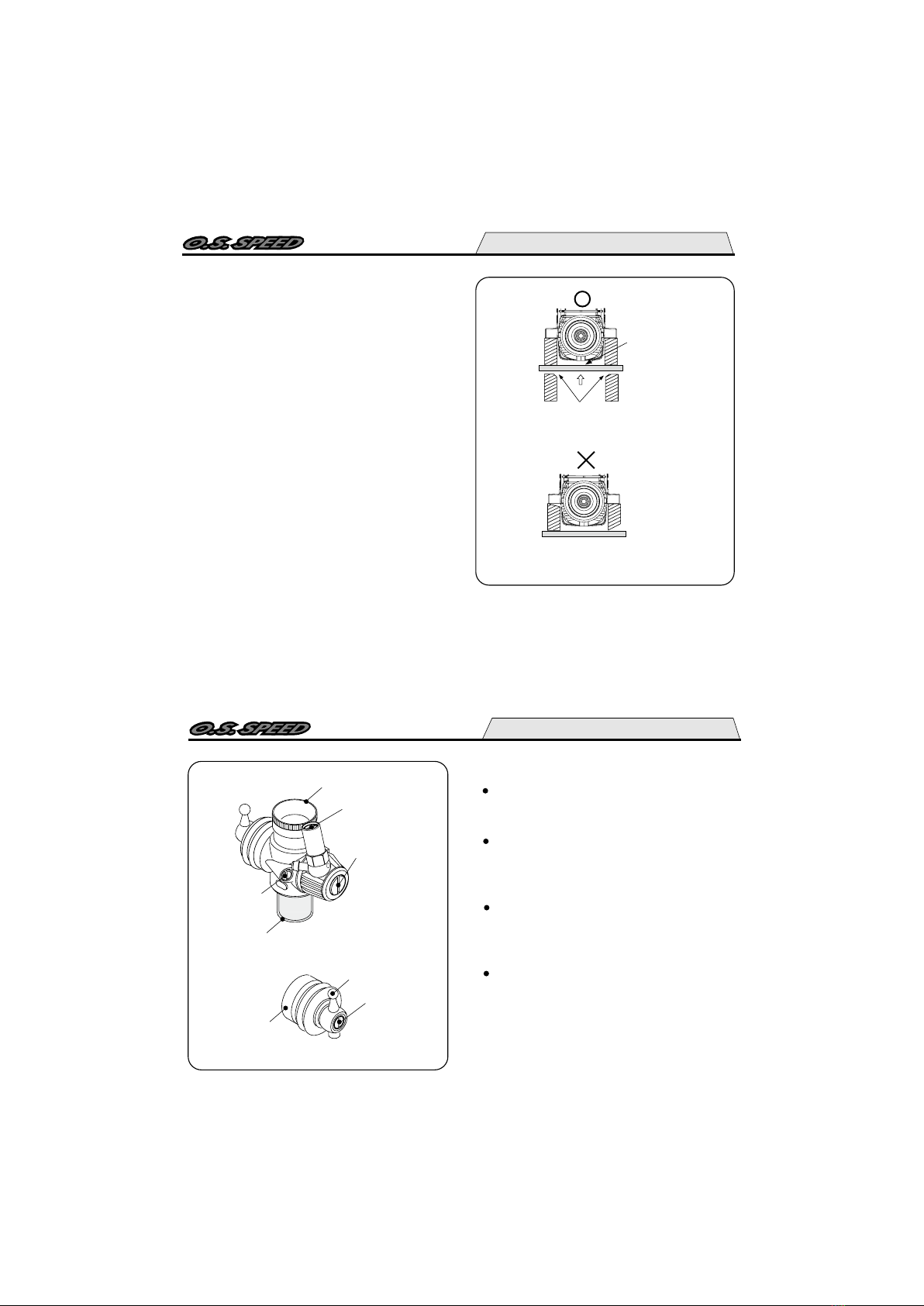
INSTALLATION OF THE CARBURETOR
As delivered, the engine has its carburetor lightly
installed in the intake boss. Secure it as follows.
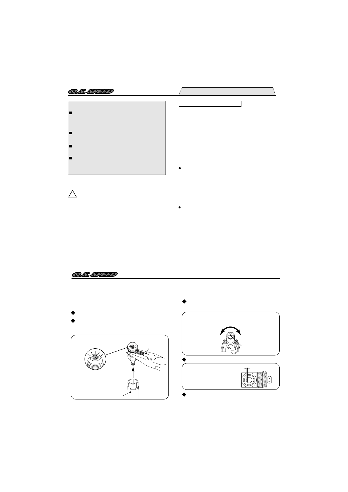
Loosen the retainer screw, rotate the
carburetor to its correct position and make
sure that it is pressed well down into the
intake boss, compressing the rubber gasket,
before retightening screw.
1.
2.
Rotate the retainer nut
gently until it stops.
Tighten a further
120-180
Rotate the retainer screw gently until it
stops, then tighten a further 120-180 .
Do not overtighten the screw as this will
damage the thermo insulator.
Note
Be careful not to damage the O rings when
removing the carburetor retainer from the
engine.
First, remove the retainer Retaining screw,
then pull out each part. Do not push the
part in or damage the O rings.
Retaining Screw
"O" Ring
"O" Ring

16
ENGINE INSTALLATION
Make sure that the vehicle's engine mounting
surfaces are level and in the same plane. Poor
installation may cause distortion of the
crankcase, bearings, etc., resulting in erratic
running and loss of performance.
The recommended screws for securing the
engine are 3mm or 4-40 steel Allen hexagon
socket type.
If existing holes in the engine mount do not align
perfectly with engine mounting lugs, enlarge
them slightly with a needle-file so that screws are
in alignment with the mounting holes.
Also, make sure the engine does not interfere
with chassis, etc.
Chamfer inside edges of bearers.
Do not allow bottom
of crankcase to
touch chassis.
17
CARBURETOR CONTROLS 12F(B)
The Needle-Valve(Adjusted at the factory):
The Mixture Control Valve:
Four adjustable controls are provided on
this carburetor.
For adjusting the mixture strength when the
throttle is fully open.
For changing the mixture strength at mid
speed and acceleration. (Do not rotate the
screw more chan one turn.)
The Throttle Stop Screw
(Adjusted at the factory):
For setting the minimum idle speed:
For adjusting the mixture strength at part-
throttle and idle speed, to obtain steady
idling and smooth acceleration to mid speed.
The Metering Needle:
NOTE: Readjustment may be necessary,
occasionally to allow for changes in fuel
formula, gear ratio or clutch engagement
point.
Metering Needle
Throttle Stop
Screw
Mixture Control Valve
Needle Valve
Thermo Insulator
Carburetor Reducer
Ball Link No.5
Dust Cover

18
STARTING THE ENGINE & RUNNING-IN ('Breaking-in)
PRESSURIZED FUEL SYSTEM
!
Before starting the engine, always
check the tightness of all the screws
and nuts especially those of joint and
movable parts such as throttle arm.
Missing retightening the loose screws
and nuts often causes the parts break-
age that is capable of harming you.
Never run your vehicle without installing the air
cleaner. Dust and dirt that may otherwise be drawn
into the engine will rapidly shorten its life.
The somewhat violent changes of vehicle attitude
that occur in off-road running, combined with the
fact that, in buggy type cars, the fuel tank is often
located some distance from the carburetor, means
that the fuel 'head' at the carburetor can vary and
upset running.Therefore,it is recommended that a
muffler pressurized fuel feed system be used.
Running- in is a procedure for an engine to come
close to actual running conditions (fuel, r.p.m.,
engine temperature, etc.).
Excessively rich running and prolonged low
speed running should be avoided. Prolonged low
speed running and low temperature running may
result in the oil in the fuel becoming gelled and
the piston/liner becoming stuck together.
Please do not run on a public street, this
could cause serious accidents, personal
injuries and/or propetry damage.
Please do not run near pedestrians or
small children.
Please do not run in small or confined
areas.
Please do not run where loud noises can
disturb others, such as hospitals and
residential areas.
While Operating RUNNING-IN ('Breaking-in)
19
The following procedure is suitable for these
engines when the O.S. T-1060 tuned silencer
and a fuel containing 20% nitromethane are
used.
Fill the tank completely with fuel.
Temporarily remove the glowplug to check
that it glows bright red when energized.
Glow Plug Igniter
Pliers
Element glows when energized.
Replace the plug when the
element does not glow or is
burnt out.
Turn the needle-valve clockwise until it stops. This
is the fully closed position. Do not force it to turn
further.
Metering needle and mixture control valve
are set at basic position. (Refer to P25.)
Needle Valve
Open Close (clockwise)
approx 0.5mm
The carburetor is set as shown below at the
factory. Start the engine as it is.
The needle-valve is set approx. 2.5 turns
opened from the fully closed position.
Throttle is set approx. 0.5mm open.
Approx. 0.5mm open
factory setting with the
reducer removed

20
Turn the engine with starter box to draw fuel
into the engine.
Fuel
Deliver fuel into the carburetor.
Fuel tank side
Now connect glowplug battery lead to heat
the plug filament and start the engine.
Switch on the transmitter and make sure
that each linkage moves correctly.
approx 1mm
Set the throttle opening a little wider that the
factory setting by adjusting the Throttle Stop
Screw.
When the engines does not start or stops
right after started, try the followings.
When the engine starts, warm it up by
repeatedly increasing the rpm to medium
speed and back again to a fast idle with the
mixture set very rich, the glowplug
connected, and the driving wheels clear of
the ground. The rich mixture will provide
adequate lubrrication and cooling indicated
by profuse exhaust smoke.
Set the needle-valve approx. 2 turns open
from the fully closed position. Do not force
the needlevalve to turn beyond a lightly
closed position.
21
It is vitally important to set
the throttle at the correct
position before starting the
engine. If the engine is
allowed to run with the throttle
too far open under ''no load'' conditions (i.e.
with the driving wheels not in contact with
the
ground) it will rapidly over-heat and may be
seriously damaged.
Attention:
Next, disconnect the glowplug battery and try
running the car on the track.
If the engine stalls, open the throttle
fractionally, but try to keep the engine running
as rich as possible: if it stops because of
being excessively over-rich, close the Needle-
Valve 15˚ and try again.
throttle trigger
Run the car on the track until one tank of fuel
has been consumed, then close the Needle-
Valve 15˚ and run the car for 3 to 5 full tanks
of fuel.
Repeat this procedure until approx. 2 liters of
fuel have been consumed, during which time
the throttle may be opened for brief bursts of
increased power.
If the engine stops at medium speeds, close
the Mixture Screw 45˚.

22
Needle
The position of the needle-valve
when starting the engine.
Close the needle-valve approx.
15˚ after running the vehicle for
3 to 5 full tanks of fuel.
Repeat this procedure until
approx. 2 liters of fuel have
been consumed.
Note:
In the event of any major working parts
(e.g. piston/cylinder liner assembly) being
replaced or the fuel being changed,
especially to high nitro fuel, the complete
running-in should be repeated.
Warning!
Do not touch rotating parts, engine and si-
lencer when stopping the engine as they
become very hot, and contact with them
may result in a serious burn.
To stop the engine, close the throttle to idle
speed and shut it off completely with the trim
lever on the transmitter then cut off the fuel
supply by pinching the fuel delivery tube to
the carburetor.
Fuel
How to stop the engine
23
FINAL ADJUSTMENT
Throttle
Stop Screw
Needle Valve
Metering
Needle
Open Close Close
Open
Needle Valve Metering Needle
More fuel Less fuel More fuel Less fuel
Run the vehicle (with throttle fully open) over
the longest available straight course, in order
to observe the model's speed. Next return
the car to the starting point, close the Needle-
Valve 15˚ and repeat the run, taking note of
the improvement in performance.
Continue with further runs, gradually
reducing the Needle-Valve setting and
aiming to achieve the highest straight-line
speed. Remember, however, that, if the
Needle-Valve is shut down too far, the
engine will overheat and, accompanied by
visibly diminished exhaust smoke, the model
will lose speed. At this point, throttle down
immediately, stop the vehicle and reopen the
Needle-Valve 15˚.
Final adjustment should be carried out only after
the running-in has been completed.

24
Warning!
Mixture adjustments (whether via the
Metering Needle, or the Needle-Valve)
cannot be made accurately under 'no-load'
conditions, which, in any case, are not
advised, since such operation carries the
risk of seriously damaging the engine
through over-revving and overheating.
With the engine running, close the throttle
and allow it to idle for about five seconds,
then reopen the throttle fully. If, at this point,
the engine puffs out an excessive amount of
smoke and the vehicle does not accelerate
smoothly and rapidly, it is probable that the
idle mixture is too rich.
Carry out adjustments patiently, under actual
running conditions, until the engine responds
quickly and positively to the throttle control.
In this case, turn the Metering Needle
clockwise 15˚. If, on the other hand, the
engine tends to speed up momentarily and
then cut out abruptly when the throttle is
opened, the idle mixture is too lean. Correct
this by turning the Metering Needle
counter-clockwise 15˚.
With the optimum mixture control position,
light smoke is visible during high speed
running,and the engine rpm increases
smoothly during acceleration. Remember
that, if the engine is operated with the fuel/air
mixture slightly too lean, it will overheat and
run unevenly. As with all engines, it is
advisable to set both the needle-valve and
metering needle slightly on the rich side of
the best rpm setting, as a safety measure.
25
If the engine runs too fast with the throttle
closed, the throttle stop screw should be
turned counter-clockwise to allow the throttle
opening to be reduced.
Finally, beyond the nominal break-in period,
a slight readjustment toward a leaner needle
setting may be required to maintain
maximum performance.
REALIGNMENT OF METERING NEEDLE AND
MIXTURE CONTROL VALVE
In the course of making carburetor
adjustments, it is just possible that the
Metering Needle and the Mixture Control
Valve may be inadvertently screwed in or out
too far and thereby moved beyond its
effective adjustment range.
The basic positions can be found by rotating
the Metering Needle until its slotted head is
flush with the ball link body.
Mixture Control Valve
Carburetor Body
Slide Valve
Carburetor Body
Metering Needle
Rotate the Metering Needle
until its slotted head is flush
with the ball link body.
This is the basic position.
Ball Link
Rotate the Mixture Control
Valve until its slotted head is
flush with the carburetor body.
This is the basic position.

26
CARE AND MAINTENANCE
1.
2.
3.
The minute particles of foreign matter, that
are present in any fuel may, by accumulating
and partially obstructing fuel flow, cause
engine performance to become erratic and
unreliable.
O.S. 'Super-Filters' (large and small) are
available, as optional extras, to deal with this
problem.
One of these filters installed to the pickup
tube inside your refueling container, will
prevent the entry of foreign material into the
fuel tank. It is also recommended that a good
in-line filter be installed between the tank and
carburetor.
Do not forget to clean the filters regularly to
remove dirt and lint that accumulate on the
filter screens. Also, clean the carburetor
itself occasionally.
At the end of each operating session, drain out
any fuel that may remain in the fuel tank.
Afterwards,energize the glow-plug and try to
restart the engine, to burn off any fuel that may
remain inside the engine. Repeat this
procedure until the engine fails to fire. Do this
while the engine is still warm.
4. Then, inject some after-run oil into the
engine, and rotate the engine with an
electric starter for 4 to 5 seconds to
distribute the oil to all the working parts.
Note:
Do not inject after-run oil into the
carburetor as this may cause the O-rings
inside the carburetor to deteriorate. These
procedures will reduce the risks of starting
difficulties or corrosion after a period of
storage.
27
Dirt and dust may lodge in marked places.
CHECKING THE ENGINE
If the engine will not develop normal performance
after a long period of running due to wearing of
parts. It is suggested to replace necessary
parts when the following symptoms are detected.
Engine sound changes and easily overheats.
Power has dropped excessively.
Idle is unstable and/or engine tends to stop
at idle.
In most cases, ball bearings, cylinder & piston
assembly, connecting rod and/or crankcase have
become worn out or damaged. Check the
parts carefully and replace them if necessary.
Crankshaft of this engine is filled with
silicone. Do not use light oil nor
kerosene, etc. for washing, or the silicone
will swell. Use alcohol or fuel for washing
and dry it completely.
Note:
5. Finally, when cleaning the exterior of the
engine, use methanol or a household
cleaning agent. Do not use gasoline,
kerosene, or any petroleum based chemical
which can damage silicone fuel tubing.

28
TROUBLE SHOOTING
Symptom
Cause Corrective action
Engine fails to fire.
Fuel tank is empty.
Fuel not reaching the engine.
Fill the tank with fuel and repeat
Priming procedure.
Glowplug element is burnt out.
Glowplug battery discharged
Replace glowplug.
Recharge or replace the battery.
Clogged fuel filter
Air cleaner and silencer inside is dirty.
Clean or replace fuel filter.
Replace cleaner element and clean inside silencer.
Over priming Remove glowplug and pump out excess fuel.
Fuel tubing is disconnected. Connect fuel tubing securely.
Fuel tubing is kinked, split or has a hole.
Check the tubing carefully and replace if necessary.
Incorrect servo linkage Connect correctly after setting servo at neutral.
Reverse rotating direction of starter box. Mare sure it rotates counter clockwise seen
from crankshaft side.
29
Symptom
Cause Corrective action
Engine fires intermittently but does not run.
Insufficient fuel in the tank. Fill the tank with fuel.
Deteriorated glowplug Replace glowplug.
Clogged fuel filter
Air cleaner and silencer inside is dirty.
Clean or replace fuel filter.
Replace cleaner element and clean inside silencer.
Engine overheated Wait until engine is cool.
Incorrect clutch release Adjust the tension of clutch spring.
Starting battery disconnected too soon. Do not disconnect plug battery and wait until
r.p.m. becomes stable.
Vibration causing air bubbles in fuel. Install "O" rings to the tank screws to
prevent bubbles.

30
Symptom
Cause Corrective action
Symptom
Cause Corrective action
Unstable idle
Unsuitable glowplug Use suggested glowplug in the instructions.
Unsuitable fuel
Do not use extremely high nitro or low oil content fuel.
Extremely light flywheel Add heavier flywheel.
Silencer is disconnected or has play Install silencer securely.
Not reaching expected peak r.p.m.
Insufficient warming up or running-in. Set the needle only after warming up.
Complete running-in.
Silencer or manifold is not securely connected
or disconnected.
Replace seal ring.
Check the connections and secure them.
Fuel tubing from tank is split or broken. Replace the tubing.
31
Symptom
Cause Corrective action
Symptom
Cause Corrective action
Poor response
Deteriorated glowplug Replace glowplug.
Incorrect carburetor settings Readjust low r.p.m. range with metering
needle and mixture control valve.
Incorrect setting of transmitter Exponential function.
Check the transmitter setting.
Poor r.p.m. drop
Throttle position open too far. Close metering needle to adequate position
to lower idle r.p.m.
Carburetor not fully seated Install carburetor securely.
Incorrect linkage Make sure the throttle servo linkage does not
bind and is connected correctly.
Metering needle closed too far. Open the metering meedle a little.

32
ENGINE EXPLODED VIEW
Type of screw
C…Cap Screw
*
CAP SCREW SETS (10pcs./sets)
Code No. Size Pcs. used in an engine
Cylinder Head Retaining Screw (4pcs.)
Cover Plate Retaining Screw (4pcs.)
Carburetor Retainer Retaining Screw (1pc.)
79871020
79871050
79871160
M2.6x7
M2.6x15
M3x16
1
2
3
5
4
6
7
8
9
10 11
12
14
13
C.M2.6x7
C.M2.6x15
16
15
C.M3x16
33
ENGINE PARTS LIST
The specifications are subject to alteration for improvement without notice.
Items marked * are available for only limited time.
(One year after discontinuing the production)
Outer Head
Inner Head
Head Gasket Set (2pcs.)
Cylinder & Piston Assembly
Piston Pin
Piston Pin Retainer (2pcs.)
Connecting Rod
Built-Up Parts Set (No.4.5.6.7)
Carburetor Complete (Type 12F(B))
Carburetor Retainer Assembly
Crankshaft Ball Bearing (Front)
Crankcase
Crankshaft Ball Bearing (Rear)
Crankshaft
Cover Gasket
Cover Plate
Glow Plug RP6
Exhaust Seal Ring (2pcs.)
Dust Cap Set ( 3mm 1pc,16mm 2pcs.)
Description
Code No.
No.
1
2
3
4
5
6
7
8
9
10
11
12
13
14
15
16
*
*
*
*
*
*
*
*
21654010
21654110
21531410
21653000
21536000
21817000
21655000
21653300
21682000
21538170
22631020
21651010
21931100
21652010
21921800
21537000
71642060
21427200
21682950

34
CARBURETOR EXPLODED VIEW
Type of screw
S...Set Screw S.M3x3
1
1-1
1-2
2
2-1
3
4
89
10
57-1
7
3-1
11
3-1
4-1
6
9-1
2-2
35
The specifications are subject to alteration for improvement without notice.
CARBURETOR PARTS LIST
Mixture Control Valve Assembly
"O" Ring (L) (2pcs.)
"O" Ring (S) (2pcs.)
Needle Valve Assembly
"O" Ring (2pcs.)
No.14 Universal Nipple Assembly
Carburetor Reducer (5.5mm Red)
"O" Ring (1pc.)
Throttle Stop Screw
"O" Ring (S) (2pcs.)
Carburetor Body (w/Thermo Insulator)
Slide Valve
Metering Needle Assembly
"O" Ring (S) (2pcs.)
Dust Cover
Ball Link No.5
Set Screw
Thermo Insulator
Carburetor Rubber Gasket
Code No.
No. Description
1
1-1
1-2
2
2-1
2-2
3
3-1
4
4-1
5
6
7
7-1
8
9
9-1
10
11
21982700
27881820
22781800
21681900
27881820
21881950
71533255
22615000
21982620
22781800
21682100
21682200
21682500
22781800
21982520
23818430
26381501
21982900
22615000

36
O.S. GENUINE PARTS & ACCESSORIES
(71642060)
RP6
(71642070)
RP7
O.S. Glow Plug
72107400
72107410
72107420
72107430
22826140
72107460
72106172
21427200
Code No. Description
Silencer Complete Set T-1060 L52
T-1060 L52 Tuned Silencer Assembly
Silencer Ring (12) Set
(W/Ring 2pcs./Silencer C Spring 1pc.)
Silencer C Spring (12) (3pcs.)
Adapter Seal Ring (2pcs.)
Exhaust Manifold Assembly M1004
Exhaust Manifold Spring (2pcs.)
Adapter Seal Ring (2pcs.)
Silencer Complete Set T-1060
(72412000)
(72412100)
(72412200)
Super Air Cleaner 202 Assembly
202 Cleaner Body
202 Filter Element (4pcs.)
On-road Type
(72414000)
(72414100)
(72414200)
On-Road Filter Oil (20ml)
Induction Silencer
Induction Silencer Filter
(3pcs.)
37
(73300305)
(73301612)
Dust Cap Set
3mm
16mm
(5pcs.)
(3pcs.)
The specifications are subject to alteration for improvement without notice.
71410150
71410200
71410250
71410300
71411200
71411250
71412300
71413550
71413600
71413700
O.S. SPEED HEX WRENCH DRIVER 1.5
O.S. SPEED HEX WRENCH DRIVER 2.0
O.S. SPEED HEX WRENCH DRIVER 2.5
O.S. SPEED HEX WRENCH DRIVER 3.0
O.S. SPEED HEX BALL WRENCH DRIVER 2.0
O.S. SPEED HEX BALL WRENCH DRIVER 2.5
O.S. SPEED FLAT HEAD SCREWDRIVER 3.0
O.S. SPEED NUT DRIVER 5.5
O.S. SPEED NUT DRIVER 6.0
O.S. SPEED NUT DRIVER 7.0
(71520100)
(71415100)
(71415200)
(71415300)
71414015
71414020
71414025
71414030
71414120
71414125
71414230
71414355
71414360
71414370
O.S. SPEED HEX WRENCH TIP ONLY 1.5
O.S. SPEED HEX WRENCH TIP ONLY 2.0
O.S. SPEED HEX WRENCH TIP ONLY 2.5
O.S. SPEED HEX WRENCH TIP ONLY 3.0
O.S. SPEED HEX BALL WRENCH TIP ONLY 2.0
O.S. SPEED HEX BALL WRENCH TIP ONLY 2.5
O.S. SPEED FLAT HEAD SCREWDRIVER TIP 3.0
O.S. SPEED NUT DRIVER TIP ONLY 5.5
O.S. SPEED NUT DRIVER TIP ONLY 6.0
O.S. SPEED NUT DRIVER TIP ONLY 7.0
O.S. SPEED DRIVER TOOL
Code No. Description
O.S. SPEED
CLUTCH WRENCH & ADJUSTER
O.S. SPEED FLYWHEEL KEY
O.S. SPEED FLYWHEEL PULLER
O.S. SPEED PLUG WRENCH
Code No. Description

38
■
■
■
■
■
■
Displacement
Bore
Stroke
Practical R.P.M.
Power output
Weight
SPECIFICATIONS
THREE VIEW DRAWING
Dimensions (mm)
2.1 cc (0.128 cu.in.)
13.8 mm (0.543 in.)
14.0 mm (0.551 in.)
5,000-44,000 r.p.m.
1.75 ps / 35,000 r.p.m.
220g (7.76 oz.)
25.4
39
70.6
15.1
34.9
29.5
UNF1/4-28
1
11
31.4
4- 3.3
C
Copyright 2010 by O.S.Engines Mfg. Co., Ltd. All rights reserved. Printed in Japan.
60092370 061000
TEL. (06) 6702-0225
FAX. (06) 6704-2722
6-15 3-Chome Imagawa Higashisumiyoshi-ku
Osaka 546-0003, Japan
Table of contents
Other O.S. Speed Engine manuals
Popular Engine manuals by other brands

Westerbeke
Westerbeke 44A FOUR-35 C THREE Operator's manual

Briggs & Stratton
Briggs & Stratton 252700 Operating and maintenance instructions

NACIONAL MOTOR
NACIONAL MOTOR Derbi Euro 3 Workshop manual

Briggs & Stratton
Briggs & Stratton PROFESSIONAL SERIES 110000 Operator's manual

Volvo Penta
Volvo Penta V8-380 Operator's manual

IQ
IQ Vertiq 8108 instruction manual