Nemalux RH-20 Series User manual
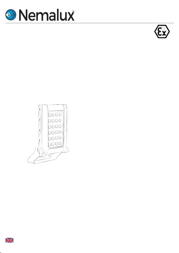
High Power Luminaire Range - Installation Guide
Zone 1 and 21 Variant CML 17ATEX1148 & IEC Ex CML17.0074 or CML21UKEX1102 Zone 2 and
22 Variant CML 17ATEX4149 & IEC Ex CML17.0074 or CML21UKEX4101 Zone 21 Dust only
Variant CML 18ATEX3161 & IEC Ex CML18.0087 or CML21UKEX3107
This installation guide provides instructions for installing the RH Highbay/ Floodlight series of
explosion protected floodlights.
Overview
1
2
3
4
5
Safety Instructions
Installation
Maintenance Technical
Specification Trouble
Shooting
Important information
The RH-20/25 series of explosion protected floodlights/highbay are specialist devices,
certified for use in specific operating environments.
The units must be installed in accordance with these instructions, must be correctly certified
for the specific operating environment and must be installed by suitably qualified personnel.
If you have any queries about the installation or the certification of the unit – please contact
Nemalux for immediate assistance and advice.
RH Series
rev. A-21
1-12
SUBJECT TO CHANGE WITHOUT NOTICE
MADE IN UK
1. Safety instructions
1. Read this leaflet carefully before commencing to install the RH unit and retain it for
future use. Installation can only be carried out by suitably qualified personnel.
2. Check the certification to ensure that the Zone, mains supply, ambient temperature
present and ‘T’ rating are suitable for the environment the unit is being installed in.
3. DO NOT open when energised.
4. If the RH unit is to be installed in areas of high vibration, please consult with Nemalux.
5. The RH unit housing is constructed from marine grade aluminium and toughened glass,
gaskets are silicone sponge, black encapsulant and o rings are silicone rubber, internally
some components are non-metallic. The end user must ensure that these materials are
suitable for the environment the RH unit will be installed in; Zone 1 and Zone 2 Hazardous
areas.
6. Check certification nameplate on side of floodlight/highbay to ascertain type of threaded
cable entry on the luminaire. Select suitably certified ATEX/IEC Ex /UKEX cable glands and
stopper plugs, these must be parallel thread, have a minimum of 5 full thread
engagement and be of a medium/fine tolerance to ISO965-1 and ISO965-3. The cable
entry devices selected must maintain the IP rating of the luminaire
7. The incoming mains cable should not exceed a temperature rise of 20°C above the
ambient conditions; select suitable cable.
8. To ensure the safety of the equipment, ensure that the ‘flamepath’ on Zone 1 variants
are free from any corrosion. No repairs are possible to flameproof joints – if in doubt
please consult the manufacturer.
9. External fasteners must have a yield strength of at least 600N/mm2
10. On Zone 1 variants the LED assembly contains no user serviceable parts, the luminaire
must not be operated without all the individual LED polycarbonate covers in position, the
IP66 rating must be maintained.
11. When the unit is installed correctly and in accordance with these installation instructions it
will not harm humans or animals.
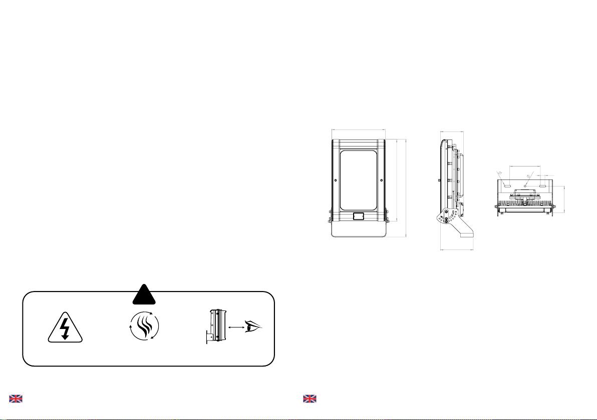
!
Install in a well
ventilated area
Do not continually
stare at lamp
Isolate mains before
removing cover
1.5m
2. Installation
Mounting RH Unit
1. To meet the requirements of certification a MINIMUM of 2 fixing points must be used,
the fixing points must be suitable for the conditions of use.
2. The line diagrams below are for guidance only – units may be mounted in any orientation
Mounting RH-20/25 Unit – Floodlight Application
151
215
350
536
639
173
200
12
30
12
151
215
350
536
639
173
200
12
30
12
151
215
350
536
639
173
200
12
30
12
2-12
SUBJECT TO CHANGE WITHOUT NOTICE
MADE IN UK 3-12
SUBJECT TO CHANGE WITHOUT NOTICE
MADE IN UK

Typical wiring diagram
LED DRIVER #1
Ex 'd' Enclosure
Ex 'e' Junction Box
LED+
LED-
N
L
DA
DA
LED1+ LED1-
L
E
N
DA
DA
LED2+
LED2-
Ex 'em' Enclosure
Ex d
Assembly
LED DRIVER #2
LED+
LED-
N
L
DA
DA
LED2+ LED2-
LED1+
LED1-
EQUI
EQUI
1
2
3
4
5
6
7
8
9
1
2
3
4
5
6
7
8
9
L
E
N
DA
DA
LED2+
LED2-
LED1-
LED1+
3. Open terminal block enclosure
4. Installer should earth the unit separately – an internal and external earth point are
provided as standard
5. Connect wires to mains supply.
6. If the unit is opened for any reason, disconnect mains
7. All RH floodlights/highbay have terminal blocks suitable for looping 4mm2 cable,
only one cable should be connected to each terminal block connection – when incoming
cables are installed a creepage and clearance of 5mm and 4mm respectively.
8. To use DALI/Dimming interface, connect the DALI terminals on the terminal block
9. Ensure no cables are trapped and gasket is seated correctly and replace terminal
block cover. Tighten to 4Nm
10. If carrying out Insulation Resistance tests the normal method of insulation testing is
to connect Live and Neutral together and test between this point and Earth to
prevent the risk of damage to the electronic control gear.
Wire the Mains cable into the terminal block. Provision has
been made for this and identified as the E (Earth), L1
(Switched Live), L2 (permanent live) and N (Neutral)
terminals. There are two pairs of contacts for each of these
to facilitate a mains cable that can be looped in and out of
the unit. The L2 terminals on a standard unit are not
electrically connected but allows them to be used on the
same circuits as emergency bulkheads.
Mounting RH-20/25 Unit – Highbay Application
422 (16.6")
353 (13.9")
536 (21.1")
457 (18")
13
(0.51")
33 (1.3")
172 (6.8")
E: Earth
N: Neutral
L1: Live
4-12
SUBJECT TO CHANGE WITHOUT NOTICE
MADE IN UK 5-12
SUBJECT TO CHANGE WITHOUT NOTICE
MADE IN UK

4. Technical Specification
120W version 300W version
Input Voltage 150-264V AC/DC or 110-254V AC/DC
Input Current (230Vac, full load) 0.52A 1.4A
Consumption 120W 300W
Power Factor (230Vac, full load) >0.97
Mains Frequency 50/60Hz
Inrush Current (Ipeak @50%) 53A, ∆t < 300µs 60A, ∆t < 300µs
Total Harmonic Distortion (230Vac, full load) ≤3%
IP Rating IP66
Weight (std) 22Kg 23Kg
Dimensions See previous pages for line diagrams
ATEX and IECEx and UKEX Rating See page 6
Twidth
Inrush Current Typical Curve
Ipeak
3. Maintenance
1. It is essential that all RH units are maintained in accordance with the
requirements of the EN60079-17 standard: (Electrical apparatus for explosive gas
atmospheres – other than mines).
2. IMPORTANT. No modifications are permitted to the unit, all spare parts must be
purchased from the manufacturer, unauthorized modifications or spare parts will
invalidate certification and make the equipment dangerous.
3. Isolate the RH unit from the mains supply and allow to cool before carrying out any
maintenance work.
4. The unit has 2 independent power supplies; in the event that a power supply needs to be
replaced remove the flameproof cover to get access to the power supply. Remove the
power supply from the mains terminals then remove LED red and black wires. If
replacing a power supply on a Zone 2 luminaire the orange silicone gasket should be
replaced at the same time to maintain the restricted breathing properties of the
enclosure, the gasket is located in the machined groove, all replacement gaskets
must be supplied via Nemalux
5. Disposal of packaging, RH units and old LED assemblies/power supplies should be
carried out in accordance with national regulations.
PROTECTION/CERTIFICATION
PROTECTION/CERTIFICATION – ZONE 1/21 VARIANTS
CML17ATEX1148 or IEC Ex CML17.0074 or CML21UKEX1102
II 2 GD Ex db eb mb IIB T4 Gb
Ta -50oC to +50oC
Ex tb IIIC T104°C Db
Ta -50°C to +50°C
IP66 150-264V AC/DC or 110-254V AC/DC
PROTECTION/CERTIFICATION – ZONE 2/22 VARIANTS
CML17ATEX4149 or IEC Ex CML17.0074 or CML21UKEX4101
II 3 GD Ex nR ec IIC Gc
Ta -50oC to +50oC
Ex tb IIIC T104°C Dc
Ta -50°C to +50°C
IP66 150-264V AC/DC or 110-254V AC/DC
PROTECTION/CERTIFICATION – ZONE 21 DUST ONLY VARIANTS
CML18ATEX3161 or IEC Ex CML18.0087 or CML21UKEX3107 Ex tb
IIIC T104°C Db
Ta -50°C to +50°C
IP66 150-264V AC/DC or 110-254V AC/DC
6-12
SUBJECT TO CHANGE WITHOUT NOTICE
MADE IN UK 7-12
SUBJECT TO CHANGE WITHOUT NOTICE
MADE IN UK

4.1 DALI Wiring Instructions
Cross section in mm2
Maximum cable length L in m
25°C 50°C 75°C
0.14 31 28 26
0.50 112 102 93
0.75 168 153 140
1.00 224 204 187
1.50 300 300 281
2.00 300 300 300
2.50 300 300 300
5. Troubleshooting
1. Ensure the two LED boards are correctly wired to terminal block. Red to Red : Black to
Black – paired cables
2. Ensure Mains input is correctly connected.
3. Ensure Mains Input is turned on at the source.
4. If LED panel fails to light is it possible to identify if problem is with LED panel or power
supply by swapping LED cables to opposite power supply to help identify problem.
Max number of fittings allowed per MCB
MCB Type Rating RH-20
(240W Version)
RH-25
(300W Version)
B 10A 2 1
B 16A 4 3
B 20A 5 4
B 25A 7 6
C 10A 4 3
C 16A 6 5
C 20A 8 6
C 25A 13 9
8-12
SUBJECT TO CHANGE WITHOUT NOTICE
MADE IN UK 9-12
SUBJECT TO CHANGE WITHOUT NOTICE
MADE IN UK

Declaration Of Conformity
With The Atex Directive 2014/34/EU
& UK Directive SI 2016 No. 1107 (as amended)
The RH series luminaire is manufactured by Raytec Ltd. for Nemalux Inc.
Raytec Ltd. declares under our sole responsibility that the product(s) listed below
conform with the relevant provisions of directive 2014/34/EU of 20th April 2016 and
UK Directive SI 2016 No. 1107 (as amended)
Compliance with the Essential Health and Safety Requirements has been assessed by
reference to the following harmonised/designated standards -
EN 60079-0 : 2018 EN 60079-1 : 2014 EN60079-7 : 2015 + A1 2018
EN 60079-15 : 2019 EN 60079-18 : 2015 + A1 2017 EN60079-31 : 2014
Manufacturer
Description
of Equipment
Certification
Body
Certificate
numbers
Equipment
Marking
10-12
SUBJECT TO CHANGE WITHOUT NOTICE
MADE IN UK 11-12
SUBJECT TO CHANGE WITHOUT NOTICE
MADE IN UK
Raytec Ltd
Unit 15, Wansbeck Business Park
Rotary Parkway
Ashington
Northumberland
NE63 8QW
United Kingdom
RH/Spartan range of High Power Floodlights
CML
New Port Road
Ellesmere Port
CH65 4LZ
CML17ATEX1148 or IEC Ex CML17.0074 or CML21UKEX1102
CML17ATEX4149 or IEC Ex CML17.0074 or CML21UKEX4101
CML18ATEX3161 or IEC Ex CML18.0087 or CML21UKEX3107
ATEX Quality Assurance Notication CSA BV (2813)
UKCA Quality Assurance Notication CSA UK (0518)
II 2 GD Ex db eb mb IIB T4 Gb
Ta -50oC to +50oC
Ex tb IIIC T104°C Db
Ta -50°C to +50°C
IP66 150-264V AC/DC or 110-254V AC/DC
II 3 GD Ex nR ec IIC Gc
Ta -50oC to +50oC
Ex tb IIIC T104°C Dc
Ta -50°C to +50°C
IP66 150-264V AC/DC or 110-254V AC/DC
Ex tb IIIC T104°C Db
Ta -50°C to +50°C
IP66 150-264V AC/DC or 110-254V AC/DC
And also 2014/35/EU - Low Voltage Directive, 2014/30/EU - EMC Directive
Signed
Name Barry Thompson
Position Director
Dated
Serial number

1018 - 72nd Ave NE | Calgary, AB, Canada T2E 8V9
Toll Free: 1-877-NEMALUX / 1-877-636-2589
P: 1.403.242.7475
F: F: 1.403.243.6190
W: www.nemalux.com
Industrial LED Lighting designed to solve
harsh and hazardous lighting challenges.
12-12
SUBJECT TO CHANGE WITHOUT NOTICE
MADE IN UK
This manual suits for next models
1
Table of contents
Other Nemalux Lighting Equipment manuals


Popular Lighting Equipment manuals by other brands


Cooper Lighting
Cooper Lighting PROfile AR60S Specification sheet

ETC
ETC Source 4WRD Installation and user manual

Viabizzuno
Viabizzuno a1 system Installing instructions

ARANCIA
ARANCIA Pills installation guide

Govee
Govee Glide Hexagon Pro H6066 user manual

BION TECHNOLOGIES
BION TECHNOLOGIES PS | tellus po rd xs user manual