Nemalux LS Series User manual

TEMPORARY LIGHTING STRING
Intended for temporary lighting requirements in industrial, marine and hazardous locations, the LS
light stringer is rated for indoor and outdoor use. With a protection level of IP66 / NEMA4X the
versatile LS oers a lightweight solution for surface and hook mount applications during construc-
tion, operation and maintenance.
Conforms to: UL 844, UL 1088, CAN/ULC-S1088, UL 1598, UL 1598A:
CSA 22.2 No. 137
Hazardous Location Certication:
Class I, Division 2, Groups ABCD, T5;
Class II, Division 1, Groups EFG, T5;
Class III;
Class I, Zone 2, Groups IIC;
Class I, Zone 20, Groups IIIC
Housing: Copper-free Case Aluminum & Borosilicate Glass
Rated Voltage: 120 VAC , 50/60 Hz
Rated Power: 19.5W per module
Connections: Standard: Black: Line | White: Neutral | Green: Ground
Temperature Range: -50° C to +70° C
Ingress Protection: IP66/67 | Suitable for Wet Locations. Marine Outside type (Salt water).
rev. A-20
APPLICATION
TM
Nemalux
I N DUSTRIAL
LS Series
1-6
MADE IN CANADA
Installation Spec Sheet Webpage
PRE-ASSEMBLED TEMPORARY STRING LIGHTS
Refer to alternate instructions for LS-KIT
STEP 1:
Inspect shipping package and contents to ensure no
damage has occurred during shipping.
This product must be wired, installed, and maintained by a qualied electrician.
Refer to CEC/NEC codes and follow all local standards applicable to the area of installation
Make electrical connections in a Listed/Recognized junction box (Not Provided) or Listed/Recognized
connector approved for a minimum of 120VAC/8A. If the temporary lighting string will be connected
inside a classied (hazardous) zone, connector must be rated for the hazardous Class and Division/Zone
where the connection is made.
If the temporary lighting string will be installed in a wet location, the junction box or connector used
must be Listed/Recognized for use in Wet Locations.
WARNING
CAUTION: To avoid risk of re, explosion, or electric shock,
this product should be installed, inspected, and maintained
by a qualied electrician in accordance with all applicable
codes. Supply connector must be rated for location and
zone of use.
ATTENTION: Pour réduire le risque d'inammation des
atmosphères dangereuses et a n déviter les chocs
électriques, ce produit doit être installé, inspecté, et entre-
tenu par un électricien qualié conformément à tous les
codes applicables. Le connecteur d'alimentation doit être
adapté à l'emplacement et à la zone d'utilisation.
WARNING
NOTE: For use only on GFCI protected circuits when installed
with connector or plug.
VEUILLEZ NOTER: Utiliser seulement sur des prises protégées
de disjoncteur-detecteur de fuite a la terre
WARNING
CAUTION – To reduce the risk of electric shock do not
connect or disconnect when wet.
ATTENTION: Pour reduire les dangers de shoc électrique, ne
pas brancher ou debrancher une fois mouillé.
WARNING
CAUTION: To reduce the risk of ignition of hazardous
atmospheres, disconnect the luminaire from the supply
circuit before opening. Keep tightly closed when in opera-
tion.
ATTENTION: Pour réduire le risque d' inammation des
atmosphères dangereuses, débranchez le luminaire du
circuit électrique avant d'ouvrir. Conserver hermétiquement
fermé lorsqu'il est en fonctionnement.
TM
Nemalux
I N DUSTRIAL
LS Series
rev. A-20
2-6
MADE IN CANADA

STEP 2 (Optional):
Attach Surface mount accessory using supplied M4
screws (2). Torque fasteners to 20 in-lbs (2.3 N-m) or
use Strap/Stainless Steel Clamp to fasten xture to
desired location.
STEP 3:
If not ordered with pre-installed connector, install
suitable UL/CSA Listed or Recognized connector for
the environment and zone where the electrical
connection will be made or connect wiring lead to a
Listed junction box suitable for the environment and
zone of use. Ordinary location plugs may be used
only if the electrical connection to power is made
outside of all hazardous environments or classied
zones. Where connections to electrical power will be
made inside hazardous classied zones, only UL/CSA
Listed or Recognized connectors rated for the
environment, Class/Division or Zone, temperature,
and hazardous gas or dust group present may be
used.
STEP 4:
For raised installations, attach light stringer to xed
infrastructure (handrail, exposed beams, pipe rack,
etc.) in desired location with adjustable strapping,
hook, or surface mount bracket accessories. Cam
buckle straps, stainless steel mounting clamps, hook
and surface mounts are available separately.
NOTE:
For replacement of damaged Cord, refer to Assembly of
LS-KIT into Approved Temporary String Light instruc-
tions on page 3-4.
STEP 5:
Plug-in or energize circuit.
INSTALLATION (CONT.)
2
1
STAINLESS STEEL STRAP ACCESSORIES
ARE AVAILABLE IF REQUIRED
TM
Nemalux
I N DUSTRIAL
LS Series
rev. A-20
3-6
MADE IN CANADA
Step 2

STEP 1:
Inspect shipping package and contents to ensure no
damage has occurred during shipping.
ASSEMBLY OF LS-KIT INTO APPROVED TEMPORARY STRING LIGHT
Refer to alternate instructions for Pre-assembled Temporary String Lights
This product must be wired, installed, and maintained by a qualied electrician.
Refer to CEC/NEC codes and follow all local standards applicable to the area of installation
Make electrical connections in a Listed or Recognized junction box (Not Provided) or Listed/Recognized
connector approved for a minimum of 120VAC/8A. If the temporary lighting string will be connected
inside of a classied (hazardous) zone, connector must be rated for the hazardous Class and
Division/Zone where the connection is made.
TM
Nemalux
I N DUSTRIAL
LS Series
rev. A-20
4-6
MADE IN CANADA
WARNING
CAUTION: To avoid risk of re, explosion, or electric shock,
this product should be installed, inspected, and maintained
by a qualied electrician in accordance with all applicable
codes. Supply connector must be rated for location and
zone of use.
ATTENTION: Pour réduire le risque d'inammation des
atmosphères dangereuses et a n déviter les chocs
électriques, ce produit doit être installé, inspecté, et entre-
tenu par un électricien qualié conformément à tous les
codes applicables. Le connecteur d'alimentation doit être
adapté à l'emplacement et à la zone d'utilisation.
WARNING
NOTE: For use only on GFCI protected circuits when installed
with connector or plug.
VEUILLEZ NOTER: Utiliser seulement sur des prises protégées
de disjoncteur-detecteur de fuite a la terre
WARNING
CAUTION – To reduce the risk of electric shock do not
connect or disconnect when wet.
ATTENTION: Pour reduire les dangers de shoc électrique, ne
pas brancher ou debrancher une fois mouillé.
WARNING
CAUTION: To reduce the risk of ignition of hazardous
atmospheres, disconnect the luminaire from the supply
circuit before opening. Keep tightly closed when in opera-
tion.
ATTENTION: Pour réduire le risque d' inammation des
atmosphères dangereuses, débranchez le luminaire du
circuit électrique avant d'ouvrir. Conserver hermétiquement
fermé lorsqu'il est en fonctionnement.
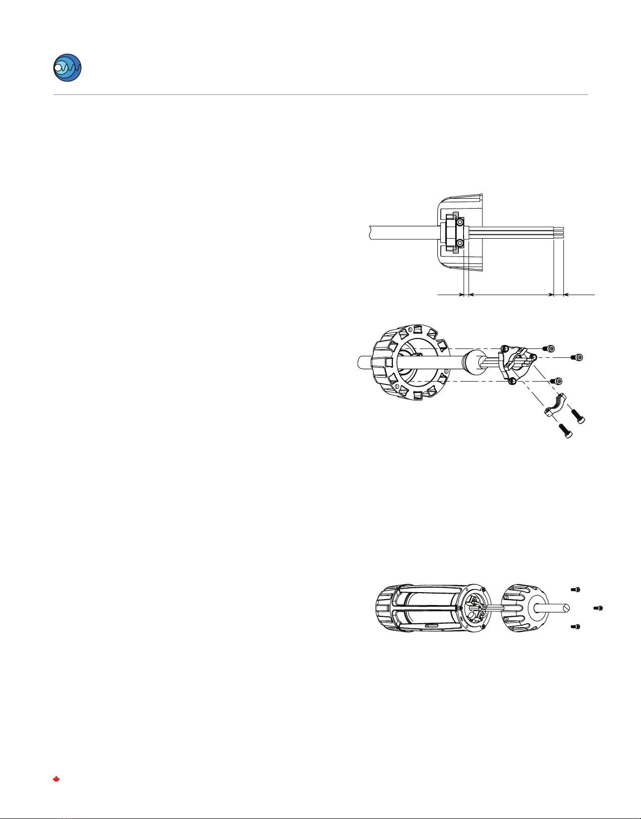
STEP 2:
Strip 95mm (3.75in) of cable jacket, and trim back any
ller. Strip conductor insulation 10mm (0.39in) from
ends. Feed wire through end cap, rubber gland, and
gland cap. Install cord clamp and tighten to 20 in-lbs
(2.3 N-m) so that cable jacket protrudes 5mm past
the end of the cord clamp.
Slide together end cap, rubber gland, and gland cap
assembly, before fastening with three M4 socket
head cap screws torqued to 20 in-lbs (2.3 N-m).
NOTE:
Electrical cord used must be 14 Gauge/3 Conductor
SOOW with an outer diameter between 13mm [0.51”]
and 14.2mm [0.56”]. SOOW cord must be rated for
600V/90˚C or higher.
Maximum string length must not exceed 300 ft.
Maximum number of lighting modules must not exceed
30 units on a single string.
STEP 3:
Connect each conductor into appropriate connectors
STEP 4:
Wrap excess conductor inside cap and gently rotate to
compress wires (without pinching them) till the assem-
bly holes align with the core and internal wires are not
strained or pinched.
Attach End Cap Assembly to the core with the supplied
M4 socket head cap screws (3) with M4 hex driver
torque to 2.3 N-m (20 in-lbs).
STEP 5:
Repeat steps 2-4 for other side of module.
INSTALLATION (CONT.)
TM
Nemalux
I N DUSTRIAL
LS Series
rev. A-20
5-6
MADE IN CANADA
Step 4
Step 2
85mm 10mm
5mm
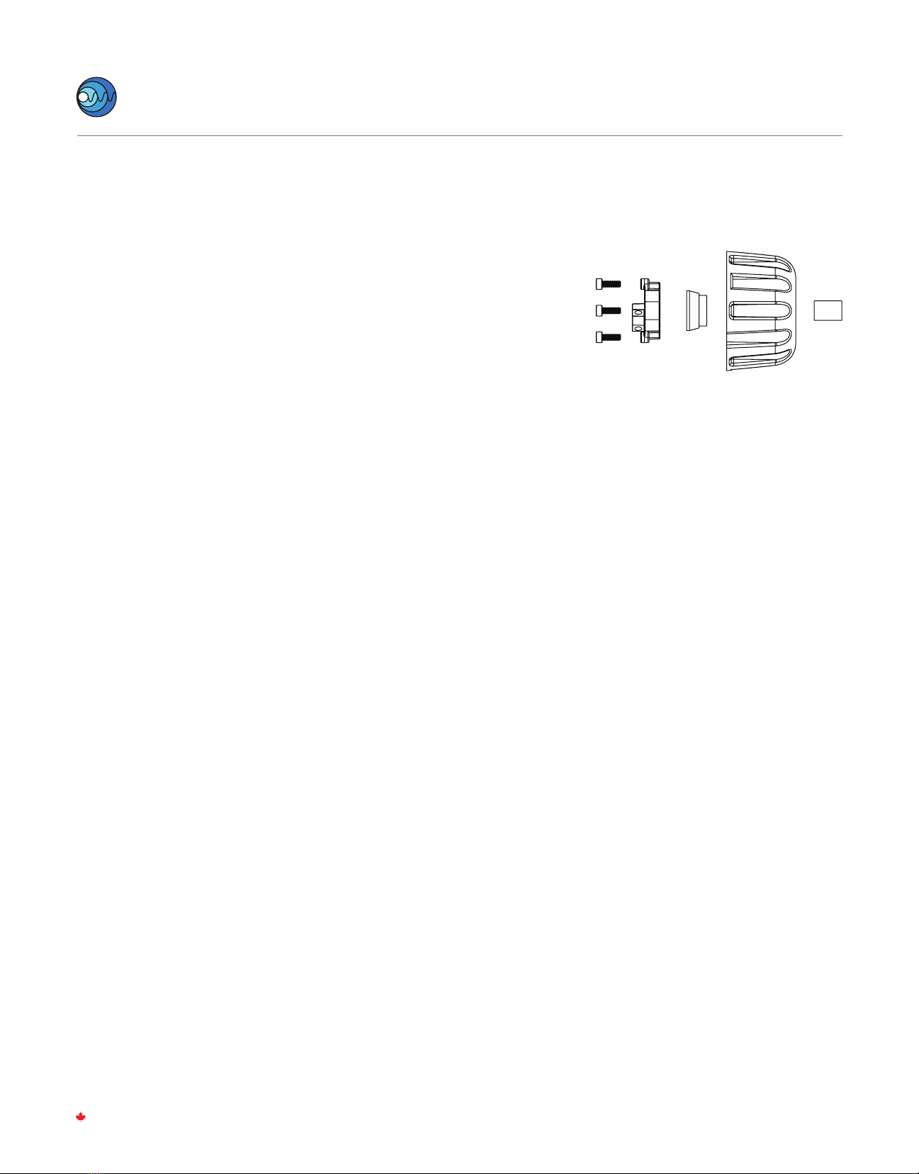
STEP 6:
To Maintain ingress protection the nal module must
have the blank end plugged. On the end module,
assemble the cord clamp and gland cap together using
two M4 fasteners and Torque to 20 in-lbs (2.3 N-m).
Install rubber Gland, Gland Cap assembly, and cylindri-
cal plug into the un-wired end-cap and torque M4
fasteners to 20 in-lbs (2.3 N-m) to secure in place and
compress gland seal around the cylindrical plug.
Attach End Cap Assembly to the core with the supplied
M4 socket head cap screws (3) with M4 hex driver
torque to 2.3 N-m (20 in-lbs).
STEP 7:
Attach mounting accessory if used (refer to Step 2 in LS
installation).
STEP 8:
Install suitable UL/CSA Listed or Recognized connector
for the environment and zone where the electrical
connection will be made or connect wiring lead to a
listed junction box suitable for the environment and
zone of use. Ordinary location plugs may be used only if
the electrical connection to power is made outside of
all hazardous environments or classied zones. Where
connections to electrical power will be made inside
hazardous classied zones, only UL/CSA Listed or
Recognized connectors rated for the environment,
Class/Division or Zone, temperature, and hazardous gas
or dust group present may be used.
STEP 9:
For raised installations, attach light stringer to xed
infrastructure (handrail, exposed beams, pipe rack, etc.)
in desired location with adjustable strapping, hook, or
surface mount bracket accessories.
Cam buckle straps, stainless steel mounting clamps,
hook and surface mounts are available separately.
INSTALLATION (CONT.)
Step 6
TM
Nemalux
I N DUSTRIAL
LS Series
rev. A-20
5-6
MADE IN CANADA
Other Nemalux Lighting Equipment manuals


