Nematron AEMQ77-989 User manual

AEMQ77-989
Intel®Q77 Express Chipset
ATX Motherboard
User's Manual
V 2.1
Release date: 2014.03

Preface
1
Contents
Copyright Notice ......................................................................... 3
Trademarks .................................................................................. 3
Revision History.......................................................................... 3
Safety Instructions ...................................................................... 3
CE Conformity ............................................................................. 5
FCC-B Radio Frequency Interference Statement..................... 5
WEEE Statement ......................................................................... 6
Chapter 1 Overview................................................................. 7
Mainboard Specifications ......................................................................7
Mainboard Layout..................................................................................9
Chapter 2 Hardware Setup.................................................... 10
Components Reference Guide ............................................................10
CPU (Central Processing Unit) ............................................................ 11
CPU & Cooler Installation .................................................................... 11
Memory .................................................................................................. 14
Dual-Channel mode Population Rule...........................................................14
Installing Memory Modules............................................................................14
Power Supply ........................................................................................15
24-Pin Power Connector: JPWR1..................................................................15
4-Pin Power Connector: JPWR2....................................................................15
Back Panel I/O.......................................................................................16
Connector..............................................................................................18
Chassis Intrusion Pinheader: CI1..................................................................18
Serial ATA Connector: SATA1 ~ SATA5.........................................................18
TPM Module Connector: JTPM1....................................................................19
Fan Power Connector: CPUFAN1, SYSFAN1, SYSFAN2, SYSFAN3..........19
GPIO Pin-header: JGPIO1 ..............................................................................20
Front Panel Pin-header: JFP1........................................................................20
Front USB Pin-header: JUSB1 ~ JUSB3.......................................................21
Serial Port Connector: COM2 ~ COM6..........................................................21
Front Audio Pin-header: JAUD1 ....................................................................23
Parallel Port Header: JLPT1...........................................................................23
Jumper...................................................................................................24
Clear CMOS Jumper: CLR_CMOS1...............................................................24
ME Jumper: ME_DIS1 .....................................................................................24
AT / ATX Select Jumper: JAT1 .......................................................................25
Back Panel COM Port Power Jumper: JCOMP1 ..........................................25

Preface
2
On-board COM Port Power Jumper: JCOMP2 ~ JCOMP6..........................25
Slot.........................................................................................................25
PCI-E (Peripheral Component Interconnect Express) Slot .......................25
PCI (Peripheral Component Interconnect) Slot ...........................................26
Mini PCI-E Slot.................................................................................................26
mSATA Slot ......................................................................................................26
Chapter 3 BIOS Setup ........................................................... 28
Entering Setup ......................................................................................28
Control KEYS...................................................................................................28
Getting Help .....................................................................................................29
General Help <F1>...........................................................................................29
The Menu Bar ........................................................................................30
Main .......................................................................................................31
Advanced............................................................................................... 32
Boot .......................................................................................................38
Security..................................................................................................39
Chipset...................................................................................................43
Power.....................................................................................................44
Exit .........................................................................................................46

Preface
3
Copyright Notice
The material in this document is our intellectual property. We take every care
in the preparation of this document, but no guarantee is given as to the
correctness of its contents. Our products are under continual improvement
and we reserve the right to make changes without notice.
Trademarks
All trademarks are the properties of their respective owners.
NVIDIA®is registered trademark of NVIDIA Corporation.
ATI®is registered trademark of ATI Technologies, Inc.
AMD®is registered trademarks of AMD Corporation.
Intel®is registered trademarks of Intel Corporation.
Windows®is registered trademarks of Microsoft Corporation.
AMI®is registered trademark of Advanced Micro Devices, Inc.
Award®is a registered trademark of Phoenix Technologies Ltd.
Realtek®is registered trademark of Realtek Semiconductor Corporation.
Revision History
Revision
Revision History
Date
V2.1
For PCB v2.x
2014/03
Safety Instructions
Always read the safety instructions carefully.
Keep this User’s Manual for future reference.
Keep this equipment away from humidity.
Lay this equipment on a reliable flat surface before setting it up.

Preface
4
The openings on the enclosure are for air convection hence protects the
equipment from overheating. DO NOT COVER THE OPENINGS.
Make sure the voltage of the power source and adjust properly 110/220V
before connecting the equipment to the power inlet.
Place the power cord such a way that people can not step on it. Do not
place anything over the power cord.
Always Unplug the Power Cord before inserting any add-on card or
module.
All cautions and warnings on the equipment should be noted.
Never pour any liquid into the opening that could damage or cause
electrical shock.
If any of the following situations arises, get the equipment checked by
service personnel:
The power cord or plug is damaged.
Liquid has penetrated into the equipment.
The equipment has been exposed to moisture.
The equipment does not work well or you can not get it work
according to User’s Manual.
The equipment has dropped and damaged.
The equipment has obvious sign of breakage.
DO NOT LEAVE THIS EQUIPMENT IN AN ENVIRONMENT
UNCONDITIONED, STORAGE TEMPERATURE ABOVE 80℃(176℉),
IT MAY DAMAGE THE EQUIPMENT.
CAUTION: Danger of explosion if battery is incorrectly replaced. Replace
only with the same or equivalent type recommended by the manufacturer.
警告使用者:
这是甲类信息产品,在居住的环境中使用时,可能会造成无线电干扰,在这种
情况下,使用者会被要求采取某些适当的对策。
废电池请回收
For better environmental protection, waste batteries should be
collected separately for recycling or special disposal.

Preface
5
CE Conformity
Hereby, we declare that this device is in compliance with the
essential safety requirements and other relevant provisions set
out in the European Directive.
FCC-B Radio Frequency Interference Statement
This equipment has been tested and found to comply with the limits for a
Class B digital device, pursuant to Part 15 of the FCC
Rules. These limits are designed to provide reasonable
protection against harmful interference in a residential
installation. This equipment generates, uses and can
radiate radio frequency energy and, if not installed and used in accordance
with the instruction manual, may cause harmful interference to radio
communications. However, there is no guarantee that interference will not
occur in a particular installation. If this equipment does cause harmful
interference to radio or television reception, which can be determined by
turning the equipment off and on, the user is encouraged to try to correct the
interference by one or more of the measures listed below:
Reorient or relocate the receiving antenna.
Increase the separation between the equipment and receiver.
Connect the equipment into an outlet on a circuit different from that to
which the receiver is connected.
Consult the dealer or an experienced radio/television technician for help.
NOTICE 1
The changes or modifications not expressly approved by the party responsible
for compliance could void the user’s authority to operate the equipment.
NOTICE 2
Shielded interface cables and AC power cord, if any, must be used in order to
comply with the emission limits.
VOIR LA NOTICE D’INSTALLATION AVANT DE RACCORDER AU RESEAU.
This device complies with Part 15 of the FCC Rules. Operation is subject to
the following two conditions:
Preface
6
1. this device may not cause harmful interference, and
2. this device must accept any interference received, including interference
that may cause undesired operation.
WEEE Statement
Under the European Union (“EU”) Directive on Waste Electrical
and Electronic Equipment, Directive 2002/96/EC, which takes
effect on August 13, 2005, products of “electrical and electronic
equipment” cannot be discarded as municipal waste anymore and
manufacturers of covered electronic equipment will be obligated to
take back such products at the end of their useful life.

Chapter 1 Overview
7
Chapter 1 Overview
Thank you for choosing AEMQ77-989, an excellent industrial computer board.
Based on the innovative Intel®Panther Point chipset for optimal system
efficiency, AEMQ77-989 supports Ivy Bridge and Sandy Bridge processor
series in socket LGA1155 and supports up to four DDR3 1066/1333/1600
UDIMM slots to provide the maximum of 32GB memory capacity.
In the advanced-level and mid-range market segment, AEMQ77-989 provides
a high- performance solution for today’s front-end and general purpose
workstation, as well as in the future.
Mainboard Specifications
CPU
(Optional)
Intel Ivy Bridge series and Sandy Bridge series
processor in socket LGA1155
Chipset
Intel Q77 PCH
Support iAMT 8.0
Memory
4 DDR3 1066/1333/1600 UDIMM slots
Supports the maximum of 32GB
LAN
Gigabit Fast Ethernet by Intel 82579LM PHY & 82583V
GbE controllers
SATA
3 SATA 3Gb/s ports by Intel Cougar Point
2 SATA 6Gb/s ports by Intel Cougar Point
RAID
SATA1~5 support Intel Rapid Storage Technology
(AHCI/ RAID 0/ 1/ 5/ 10) by Intel Panther Point
Audio
HDA Codec by Realtek®ALC887
Compliant with Azalia 1.0 specs
Graphics
Support by the installed processor
- Support 3 independent displays by Ivy Bridge
series
- Support 2 independent displays by Sandy Bridge
series
Back Panel
I/O
1 PS/2 mouse/ keyboard port
1 VGA port
1 DVI-D port

Chapter 1 Overview
8
1 Serial port
1 Displayport
2 Gigabit LAN jacks
2 USB 2.0 ports
4 USB 3.0 ports
1 Line-In audio jack
1 Line-Out audio jack
1 Mic-In audio jack
Onboard
Connectors/
Pinheaders
3 USB 2.0 pin-headers
5 Serial port connectors
1 GPIO pin-header
1 Front Audio pin-header
1 Chassis Intrusion pin-header
1 Parallel Port pin-header
1 TPM Module connector (optional)
1 Front Panel pin-header
Slot
1 PCIe x16 slot
1 PCIe x4 slot
1 Mini-PCIe slot
1 mSATA slot
5 PCI slots
1 ISA slot (optional)
Form Factor
ATX: 305mm x 244mm
Environ-
mental
Operating Temperature: 0℃to 60℃
Storage Temperature: -20℃to 80℃
Humidity: 5% ~95% RH, Non-Condensing

Chapter 1 Overview
9
Mainboard Layout

Chapter 2 Hardware Setup
10
Chapter 2 Hardware Setup
This chapter provides you with the information on mainboard hardware
configurations. Incorrect setting of jumpers and connectors may damage your
mainboard. Please pay special attention not to connect these headers in
wrong direction. DO NOT adjust any jumper while the mainboard is powered
on.
Components Reference Guide
Port Name
Port Type
CPU
LGA 1155 CPU Socket
DIMM1~4
DDR3 Memory Slots
JPWR1~2
ATX Power Connectors
Back Panel
I/O Ports
CI1
Chassis Intrusion Connector
SATA1~5
SATA Connectors
JTPM1
TPM Module Connector
CPUFAN,SYSFAN1~3
Fan Power Connectors
JGPIO1
GPIO peripheral module Connector
JFP1
Front Panel Connectors
JUSB1~3
USB 2.0 Expansion Connectors
COM2~6
Serial Port Connector
JAUD1
Front Panel Audio Connector
JLPT1
Parallel Port Connector
CLR_CMOS1
Clear CMOS Jumper
ME_DIS1
Intel AMT ME Jumper
JAT1
AT/ ATX Select Jumper
JCOM1~6
Com Port Power Jumper
PCI1~5
PCI Expansion Slots
Slot1~2
PCIe Expansion Slots
ISA1
ISA Slot
MPCIE1
Mini PCIE Slot

Chapter 2 Hardware Setup
11
MSATA1
mSATA Slot
CPU (Central Processing Unit)
When you are installing the CPU, make sure that you install the cooler to
prevent overheating. If you do not have the CPU cooler, consult your dealer
before turning on the computer.
Important
Overheating
Overheating will seriously damage the CPU and system. Always make sure
the cooling fan can work properly to protect the CPU from overheating. Make
sure that you apply an even layer of thermal paste (or thermal tape) between
the CPU and the heatsink to enhance heat dissipation.
Replacing the CPU
While replacing the CPU, always turn off the power supply or unplug the
power supply’s power cord from the grounded outlet first to ensure the safety
of CPU.
Introduction to LGA1155 CPU
The surface of LGA1155 CPU. Remember to apply some thermal paste on it
for better heat dispersion.
CPU & Cooler Installation
When you are installing the CPU, make sure the CPU has a cooler attached

Chapter 2 Hardware Setup
12
on the top to prevent overheating. Meanwhile, do not forget to apply some
thermal paste on CPU before installing the heat sink/cooler fan for better heat
dispersion.
Follow the steps below to install the CPU & cooler correctly. Wrong
installation will cause damage to your CPU & mainboard.
1. Open the load lever.
2. Lift the load lever up to fully open
position.
3. After confirming the CPU
direction for correct mating, put
down the CPU in the socket
housing frame. Be sure to grasp
on the edge of the CPU base.
Note that the alignment keys are
matched.
4. Remove the plastic cap. Engage
the load lever while pressing
down lightly onto the load plate.
Important
Visually inspect if the CPU is seated well into the socket. If not, take out the
CPU with pure vertical motion and reinstall.

Chapter 2 Hardware Setup
13
5. Secure the lever near the hook
end under the retention tab.
6. Make sure the four hooks are in
proper position before you install
the cooler. Align the holes on the
mainboard with the cooler. Push
down the cooler until its four clips
get wedged into the holes of the
mainboard.
7. Press the four hooks down to
fasten the cooler. Turn over the
mainboard to confirm that the
clip-ends are correctly inserted.
8. Finally, attach the CPU Fan cable
to the CPU fan connector on the
mainboard.
Important
Confirm if your CPU cooler is firmly installed before turning on your
system.
Do not touch the CPU socket pins to avoid damaging.
Whenever CPU is not installed, always protect your CPU socket pin with
the plastic cap covered to avoid damaging.
Please refer to the documentation in the CPU cooler package for more
details about the CPU cooler installation.
Chapter 2 Hardware Setup
14
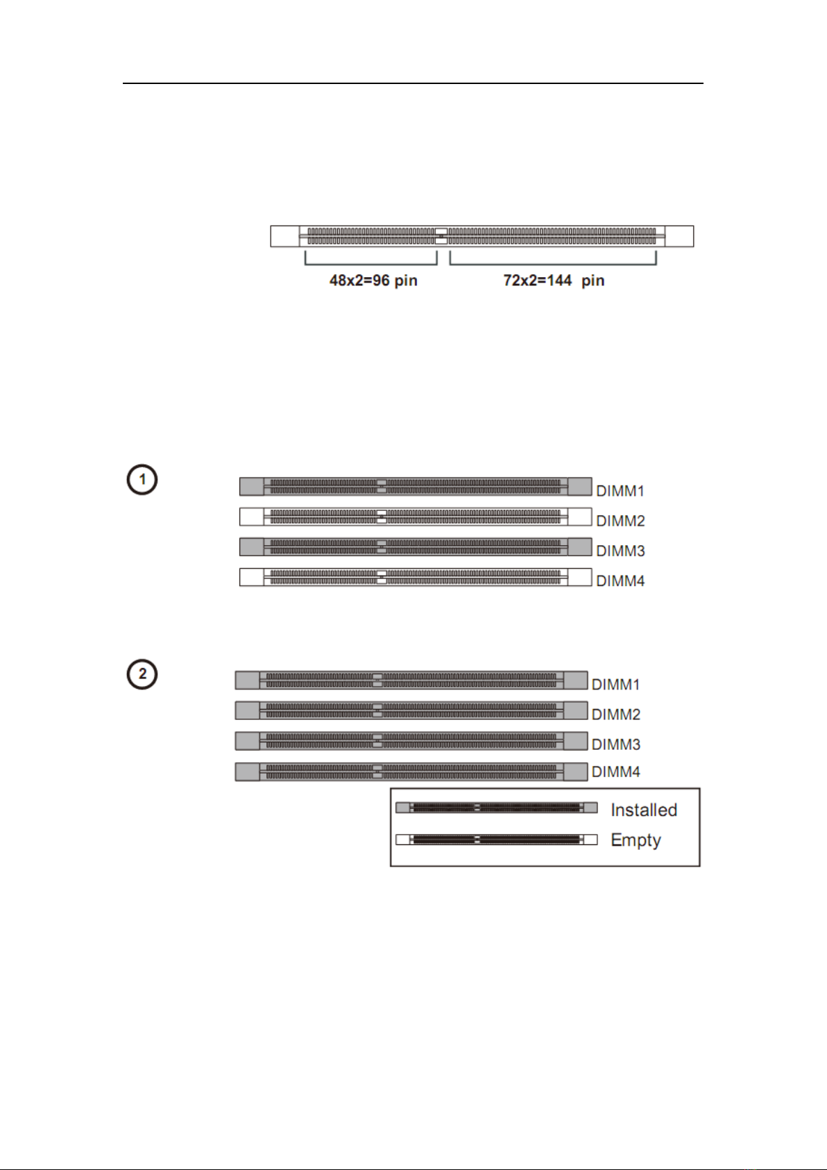
Memory
These DIMM slots are intended for memory modules.
DDR3
240-pin, 1.5V
Dual-Channel mode Population Rule
In Dual-Channel mode, the memory modules can transmit and receive data
with two data bus lines simultaneously. Enabling Dual-Channel mode can
enhance the system performance. The following illustrations explain the
population rules for Dual-Channel mode.
Installing Memory Modules
1. The memory module has only one notch on the center and will only fit in
the right orientation.
2. Insert the memory module vertically into the DIMM slot. Then push it in
until the golden finger on the memory module is deeply inserted in the
DIMM slot. You can barely see the golden finger if the memory
module is properly inserted in the DIMM slot.

Chapter 2 Hardware Setup
15
3. The plastic clip at each side of the DIMM slot will automatically close.
Important
DDR3 memory modules are not interchangeable with DDR2 and the
DDR3 standard is not backwards compatible. You should always in- stall
DDR3 memory modules in the DDR3 DIMM slots.
To enable successful system boot-up, always insert the memory modules
into the DIMM1 first.
Power Supply
24-Pin Power Connector: JPWR1
This connector allows you to connect an 24-pin power supply. To connect the
24-pin power supply, make sure the plug of the power supply is inserted in the
proper orientation and the pins are aligned. Then push down the power
supply firmly into the connector.
4-Pin Power Connector: JPWR2
This 12V power connector is used to provide power to the CPU.
Important
Make sure that all the connectors are connected to proper ATX power
Chapter 2 Hardware Setup
16
supplies to ensure stable operation of the mainboard.
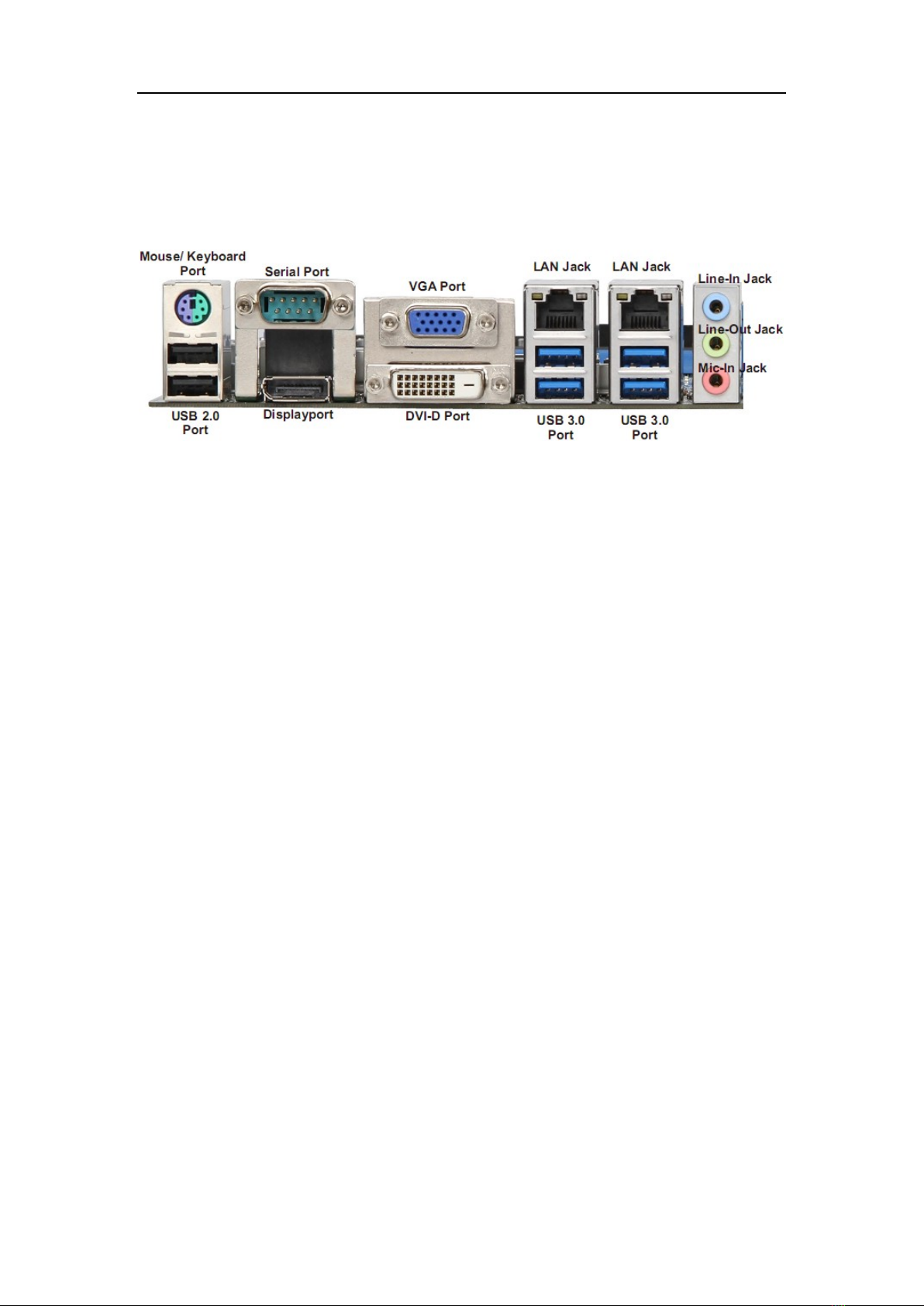
Back Panel I/O
Mouse/Keyboard Port
The standard PS/2 mouse/keyboard DIN connector is for a PS/2
mouse/keyboard.
VGA Port
The DB15-pin female connector is provided for monitor.
DVI-D Port
The DVI-D (Digital Visual Interface-Digital) connector allows you to connect an
LCD monitor. It provides a high-speed digital interconnection between the
computer and its display device. To connect an LCD monitor, simply plug
your monitor cable into the DVI connector, and make sure that the other end
of the cable is properly connected to your monitor (refer to your monitor
manual for more information.)
DisplayPort
DisplayPort is a digital display interface standard. This connector is used to
connect a monitor with DisplayPort inputs.
USB 2.0 Port
The USB 2.0 port is for attaching USB devices such as keyboard, mouse, or
other USB-compatible devices. Supports data transfer rate up to 480Mbit/s
(Hi-Speed).
USB 3.0 Port
USB 3.0 port is backward-compatible with USB 2.0 devices. It supports data
transfer rate up to 5 Gbit/s (SuperSpeed).
RS-232/422/485 Serial Port Connector
The serial port is a 16550A high speed communications port that sends/
receives 16 bytes FIFOs. You can attach a serial mouse or other serial
devices directly to the connector.
Chapter 2 Hardware Setup
17
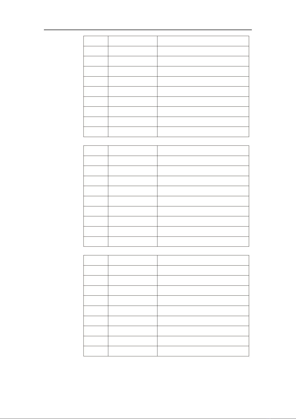
RS-232
PIN
SIGNAL
DESCRIPTION
1
DCD
Data Carrier Detect
2
RXD
Receive Data
3
TXD
Transmit Data
4
DTR
Data Terminal Ready
5
GND
Signal Ground
6
DSR
Data Set Ready
7
RTS
Request To Send
8
CTS
Clear To Send
9
VCC_COM1
Voltage select setting by J1
RS-422
PIN
SIGNAL
DESCRIPTION
1
422 TXD-
Transmit Data, Negative
2
422 RXD+
Receive Data, Positive
3
422 TXD+
Transmit Data, Positive
4
422 RXD-
Receive Data, Negative
5
GND
Signal Ground
6
NC
No Connection
7
NC
No Connection
8
NC
No Connection
9
NC
No Connection
RS-485
PIN
SIGNAL
DESCRIPTION
1
485 TXD-
Transmit Data, Negative
2
NC
No Connection
3
485 TXD+
Transmit Data, Positive
4
NC
No Connection
5
GND
Signal Ground
6
NC
No Connection
7
NC
No Connection
8
NC
No Connection
9
NC
No Connection
LAN
The standard RJ-45 LAN jack is for connection to the Local Area Network

Chapter 2 Hardware Setup
18
(LAN). You can connect a network cable to it.
Left LED
(Active LED)
Right LED
(100M/1000M
Speed LED)
LED Color
Orange
Green/Yellow
10M Cable
Plug-in
No Transmission
Orange (Lighting)
OFF
Transmission
Orange (Blinking)
OFF
100M Cable
Plug-in
No Transmission
Orange (Lighting)
Green (Lighting)
Transmission
Orange (Blinking)
Green (Lighting)
1000M Cable
Plug-in
No Transmission
Orange (Lighting)
Yellow (Lighting)
Transmission
Orange (Blinking)
Yellow (Lighting)
In S3/S4/S5 Standby State
Orange (Lighting)
OFF
Audio Jack
Line-In (Blue) - for external CD player or other audio devices.
Line-Out (Green) - for speakers or headphones.
Mic-In (Pink) - for microphones.
Connector
Chassis Intrusion Pinheader: CI1
This connector is provided to connect the chassis intrusion switch cable. If
the chassis is opened, the chassis intrusion mechanism will be activated. The
system will record this status and show a warning message on the screen. To
clear the warning, you must enter the BIOS utility and clear the record.
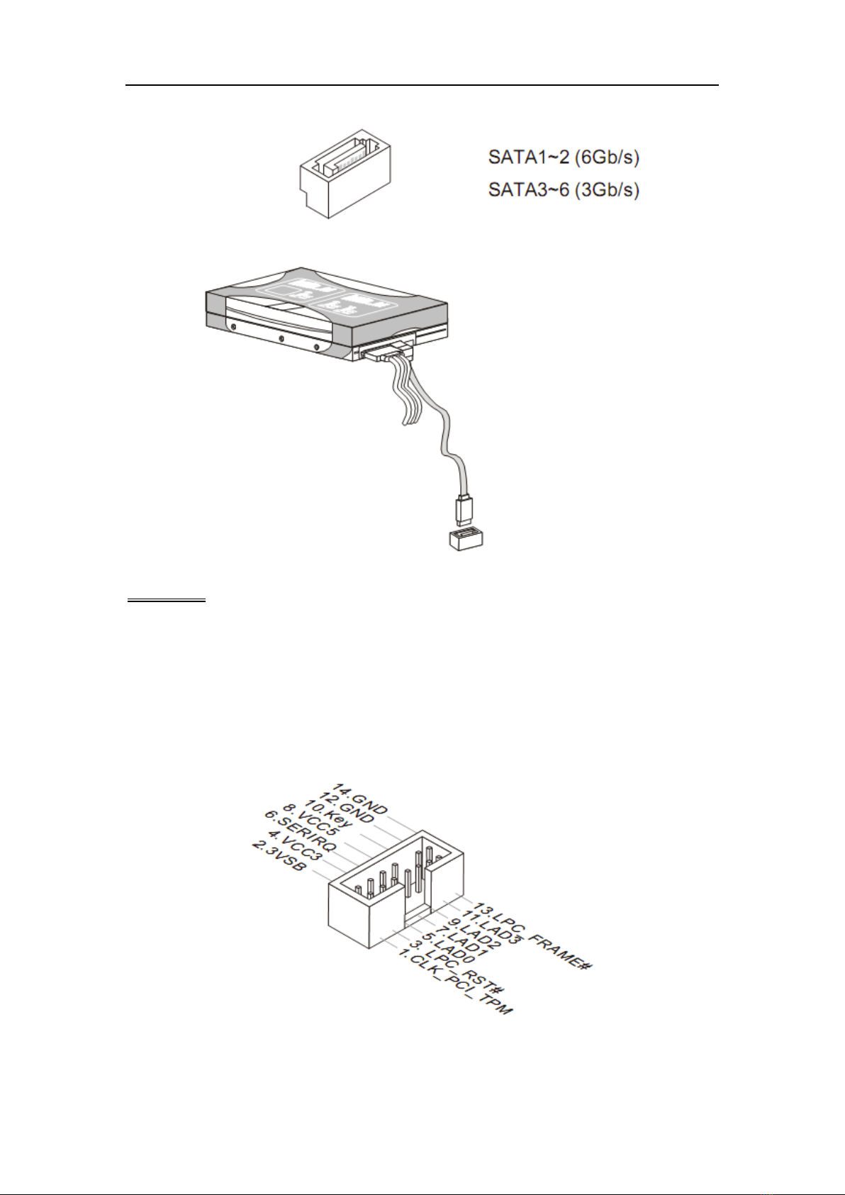
Serial ATA Connector: SATA1 ~ SATA5
This connector is a high-speed Serial ATA interface port. Each connector can
connect one Serial ATA device.
Chapter 2 Hardware Setup
19
Important
Please do not fold the Serial ATA cable into 90-degree angle. Otherwise,
data loss may occur during transmission.
TPM Module Connector: JTPM1
This connector connects to a TPM (Trusted Platform Module). Please refer to
the TPM security platform manual for more details and usages.
Fan Power Connector: CPUFAN1, SYSFAN1, SYSFAN2, SYSFAN3
The fan power connector supports system cooling fan with +12V. When
Table of contents
Other Nematron Motherboard manuals


