Nematron AEMNM10-876 User manual

AEMNM10-876
Intel®Atom D2550
Mini-ITX Motherboard
User's Manual
Version 1.2
Date: 2012.11

Preface
1
Contents
Copyright Notice ......................................................................... 3
Trademarks .................................................................................. 3
Revision History.......................................................................... 3
Safety Instructions ...................................................................... 3
CE Conformity ............................................................................. 5
FCC-B Radio Frequency Interference Statement...................... 5
WEEE Statement ......................................................................... 6
Chapter 1 Overview................................................................. 7
Mainboard Specifications ......................................................................7
Mainboard Layout...................................................................................9
Chapter 2 Hardware Setup.................................................... 10
Quick Components Guide....................................................................10
Memory.................................................................................................. 11
Installing Memory Modules............................................................................ 11
Power Supply ........................................................................................ 11
DC Power Connector: JPWR1 ....................................................................... 11
HDD Power Connector: JHDDPWR1, JHDDPWR2 ...................................... 11
Back Panel I/O.......................................................................................12
D2550 / N2800 ..................................................................................................12
N2600................................................................................................................12
Connector..............................................................................................15
Serial ATA Connector: SATA1 ~ SATA2.........................................................15
Front Panel Pinheader: JFP1 .........................................................................15
Fan Power Connector: SYSTEM_FAN1 ........................................................16
Audio Amplifier Pinheader: JAMP1...............................................................16
Front Audio Pinheader: JAUD1 .....................................................................16
Front USB Pinheader: JUSB1, JUSB2 ..........................................................17
RS-232 Serial Port Pinheader: JCOM1, JCOM3 ...........................................17
LVDS Connector: JLVDS1, JLVDS2...............................................................18
GPIO Connector: J1 ........................................................................................19
TPM Module Pinheader: JTPM1.....................................................................20
Jumper...................................................................................................20
Clear CMOS Jumper: JBAT1 ..........................................................................20
AT / ATX Select Jumper: JAT1 .......................................................................21
Serial Port Power Jumper: JCOMP1, JCOMP2, JCOMP3, JCOMP4 ..........21
Backlight Pinheader & LVDS Power Jumper: JVDD1, JVDD2....................21
Slot.........................................................................................................22
Mini-PCIe (Peripheral Component Interconnect Ex- press) Slot ...............22

Preface
2
PCI (Peripheral Component Interconnect) Slot ...........................................22
Chapter 3 BIOS Setup ........................................................... 23
Entering Setup ......................................................................................23
Control Keys ....................................................................................................23
Getting Help .....................................................................................................24
General Help <F1>...........................................................................................24
The Menu Bar ........................................................................................25
Main .......................................................................................................26
Advanced...............................................................................................27
Boot .......................................................................................................36
Security..................................................................................................37
Chipset...................................................................................................39
Power.....................................................................................................40
Save & Exit ............................................................................................41

Preface
3
Copyright Notice
We take every care in the preparation of this document, but no guarantee is
given as to the correctness of its contents. Our products are under continual
improvement and we reserve the right to make changes without notice.
Trademarks
All trademarks are the properties of their respective owners.
NVIDIA®is registered trademark of NVIDIA Corporation.
ATI®is registered trademark of ATI Technologies, Inc.
AMD®is registered trademarks of AMD Corporation.
Intel®is registered trademarks of Intel Corporation.
Windows®is registered trademarks of Microsoft Corporation.
AMI®is registered trademark of Advanced Micro Devices, Inc.
Award®is a registered trademark of Phoenix Technologies Ltd.
Realtek®is registered trademark of Realtek Semiconductor Corporation.
Revision History
Revision
Revision History
Date
V1.2
For PCB v1.x
2012/11
Safety Instructions
Always read the safety instructions carefully.
Keep this User’s Manual for future reference.
Keep this equipment away from humidity.

Preface
4
Lay this equipment on a reliable flat surface before setting it up.
The openings on the enclosure are for air convection hence protects the
equipment from overheating. DO NOT COVER THE OPENINGS.
Make sure the voltage of the power source and adjust properly 110/220V
before connecting the equipment to the power inlet.
Place the power cord such a way that people can not step on it. Do not
place anything over the power cord.
Always Unplug the Power Cord before inserting any add-on card or
module.
All cautions and warnings on the equipment should be noted.
Never pour any liquid into the opening that could damage or cause
electrical shock.
If any of the following situations arises, get the equipment checked by
service personnel:
The power cord or plug is damaged.
Liquid has penetrated into the equipment.
The equipment has been exposed to moisture.
The equipment does not work well or you can not get it work
according to User’s Manual.
The equipment has dropped and damaged.
The equipment has obvious sign of breakage.
DO NOT LEAVE THIS EQUIPMENT IN AN ENVIRONMENT
UNCONDITIONED, STORAGE TEMPERATURE ABOVE 60℃(140℃),
IT MAY DAMAGE THE EQUIPMENT.
CAUTION:
Danger of explosion if battery is incorrectly replaced. Replace
only with the same or equivalent type recommended by the
manufacturer.
警告使用者:
这是甲类信息产品,在居住的环境中使用时,可能会造成无线电
干扰,在这种情况下,使用者会被要求采取某些适当的对策。
废电池请回收
For better environmental protection, waste batteries should be
collected separately for recycling or special disposal.

Preface
5
CE Conformity
Hereby, we declare that this device is in compliance with the
essential safety requirements and other relevant provisions set
out in the European Directive.
FCC-B Radio Frequency Interference Statement
This equipment has been tested and found to comply with the
limits for a Class B digital device, pursuant to Part 15 of the
FCC Rules. These limits are designed to provide reasonable
protection against harmful interference in a residential
installation. This equipment generates, uses and can radiate radio frequency
energy and, if not installed and used in accordance with the instruction
manual, may cause harmful interference to radio communications. However,
there is no guarantee that interference will not occur in a particular installation.
If this equipment does cause harmful interference to radio or television
reception, which can be determined by turning the equipment off and on, the
user is encouraged to try to correct the interference by one or more of the
measures listed below:
Reorient or relocate the receiving antenna.
Increase the separation between the equipment and receiver.
Connect the equipment into an outlet on a circuit different from that
to which the receiver is connected.
Consult the dealer or an experienced radio/television technician for
help.
Notice 1
The changes or modifications not expressly approved by the party responsible
for compliance could void the user’s authority to operate the equipment.
Notice 2
Shielded interface cables and AC power cord, if any, must be used in order to
comply with the emission limits.
VOIR LANOTICE D’INSTALLATION AVANT DE RACCORDER AU RESEAU.
This device complies with Part 15 of the FCC Rules. Operation is subject to

Preface
6
the following two conditions:
1. this device may not cause harmful interference, and
2. this device must accept any interference received, including interference
that may cause undesired operation.
WEEE Statement
Under the European Union (“EU”) Directive on Waste Electrical and
Electronic Equipment, Directive 2002/96/EC, which takes effect on
August 13, 2005, products of “electrical and electronic equipment”
cannot be discarded as municipal waste anymore and
manufacturers of covered electronic equipment will be obligated to take back
such products at the end of their useful life.

Chapter 1 Overview
7
Chapter 1 Overview
Thank you for choosing the AEMNM10-876, an excellent industrial computer
board.
Based on the innovative Intel®NM10 chipset for optimal system efficiency, the
AEMNM10-876 accommodates the Intel®Cedarview-M / Cedarview-D
processor and supports up to 1 DDR3 1066MHz Non-ECC SO- DIMM slot to
provide the maximum of 4GB memory capacity.
In the advanced-level and mid-range market segment, the AEMNM10-876
provides a high-performance solution for today’s front-end and general
purpose workstation, as well as in the future.
Mainboard Specifications
CPU Chipset
Intel Cedarview-D D2550 / Cedarview-M N2800 /
Cedarview-M N2600 processor
North Bridge: integrated with CPU
South Bridge: Intel NM10 chipset
Memory
1 DDR3 1066MHz Non-ECC SO-DIMM slot
Supports the maximum of 4GB for D2550 / N2800
Supports the maximum of 2GB for N2600
LAN
2 Intel 82574L GbE controllers for D2550 / N2800
1 Intel 82574L GbE controller for N2600
Storage
2 SATA 3Gb/s ports by Intel NM10 chipset
1 Mini-PCIe slot for mSATA
Audio
HDA Codec by Realtek®ALC887 or ALC886
Compliant with Azalia 1.0 specs
With amplifier
Graphics
Intel 3650 series / 3600 series integrated Graphics
Engine
Resolution up to 1920 x 1200 pixels
Back Panel I/O
1 PS/2 mouse port
1 PS/2 keyboard port
1 VGA port
1 DVI-D port
2 serial ports

Chapter 1 Overview
8
2 Gigabit LAN jacks
4 USB 2.0 ports for D2550 / N2800
2 USB 2.0 ports for N2600
1 Line-In audio jack
1 Line-Out audio jack
1 Mic-In audio jack
Onboard
Connectors /
Pinheaders /
Jumpers
2 USB 2.0 pinheaders (4 ports)
1 amplifier pinheader
8 serial port pinheaders for D2550
4 serial port pinheaders for N2800 / N2600
1 GPIO pinheader
2 LVDS connectors
1 front audio pinheader
1 TPM pinheader
1 clear CMOS jumper
1 AT/ATX select jumper
4 serial port power jumpers
2 backlight pinheader & LVDS power jumpers
Slot
1 PCI slot (supports -12V)
1 Mini-PCIe slot
Form Factor
Mini-ITX: 170mm x 170mm
Environ- mental
Operating Temperature: 0oC to 60oC
Storage Temperature: -20oC to 80oC
Humidity: 0% ~ 90% RH, non-condensing
Chapter 1 Overview
9
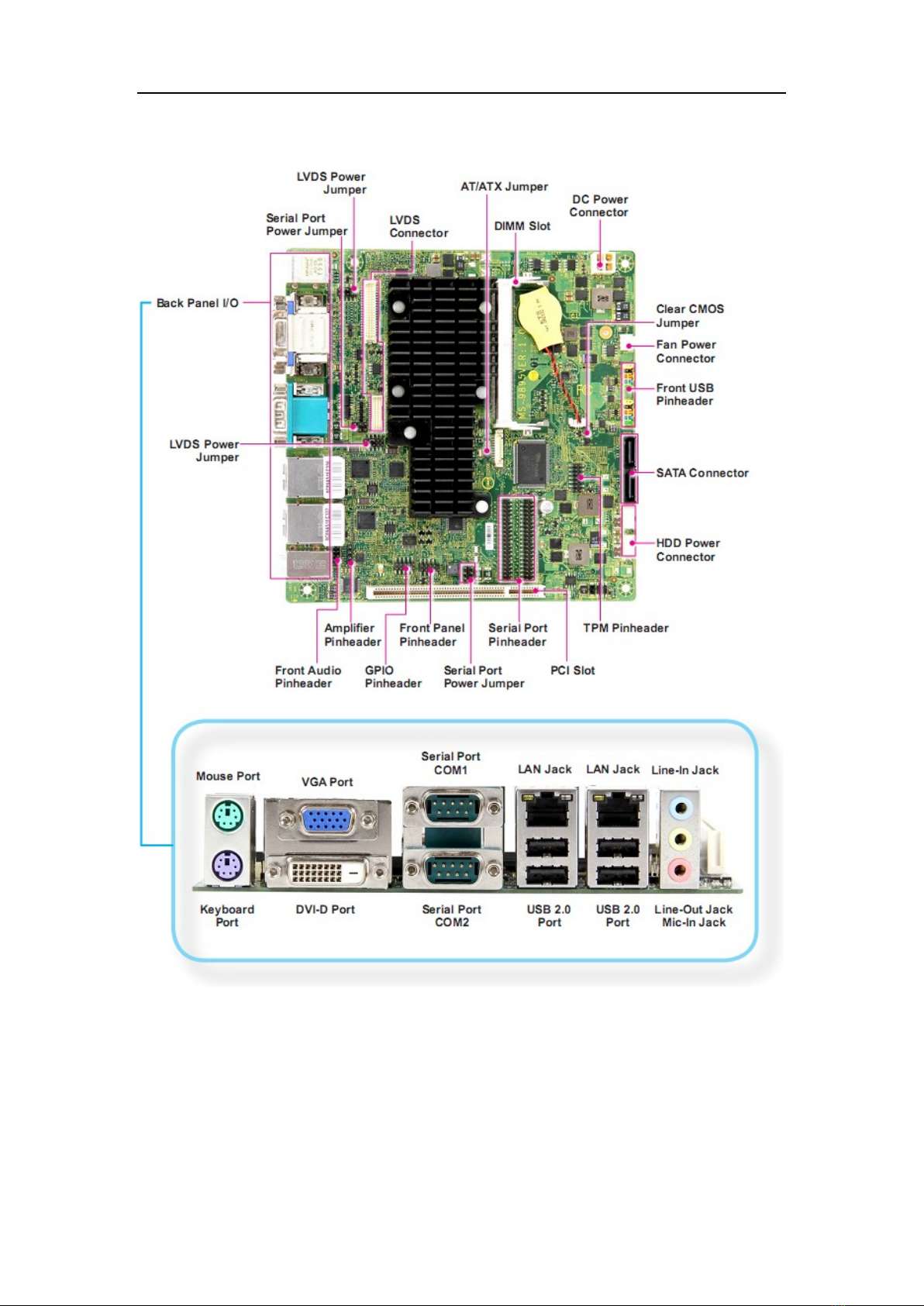
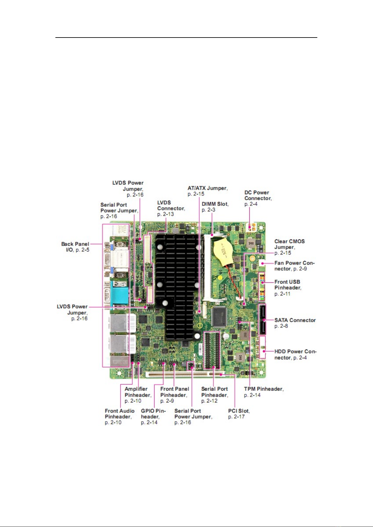
Mainboard Layout
Chapter 2 Hardware Setup
10
Chapter 2 Hardware Setup
This chapter provides you with the information on mainboard hardware
configurations. Incorrect setting of jumpers and connectors may damage your
mainboard. Please pay special attention not to connect these headers in
wrong direction. DO NOT adjust any jumper while the mainboard is powered
on.
Quick Components Guide
Chapter 2 Hardware Setup
11
Memory
Installing Memory Modules
1. Locate the SO-DIMM slot. Align the notch on the DIMM with the key on
the slot and insert the DIMM into the slot.
2. Push the DIMM gently downwards until the slot levers click and lock the
DIMM in place.
3. To uninstall the DIMM, flip the slot levers outwards and the DIMM will be
released instantly.
Important
You can barely see the golden finger if the memory module is properly
inserted in the DIMM slot.
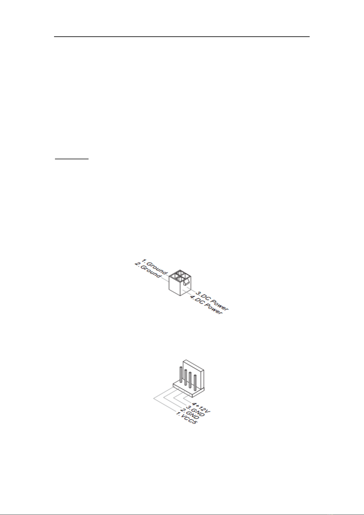
Power Supply
DC Power Connector: JPWR1
This connector provides 12/19/24V DC power input.
HDD Power Connector: JHDDPWR1, JHDDPWR2
This connector provides power to SATA hard drives.

Chapter 2 Hardware Setup
12
Back Panel I/O
D2550 / N2800
N2600
Mouse/Keyboard Port
The standard PS/2 mouse/keyboard DIN connector is for a PS/2 mouse /
keyboard.
VGA Port
The DB15-pin female connector is provided for monitor.
DVI-D Port
The DVI-D (Digital Visual Interface-Digital) connector allows you to connect an
LCD monitor. It provides a high-speed digital interconnection between the
computer and its display device. To connect an LCD monitor, simply plug your
monitor cable into the DVI connector, and make sure that the other end of the
cable is properly connected to your monitor (refer to your monitor manual for
more information.)
COM1: RS-232/422/485 Serial Port (Optional)
The serial port is a 16550A high speed communications port that sends /
receives 16 bytes FIFOs. You can attach a serial mouse or other serial
devices directly to the connector.

Chapter 2 Hardware Setup
13
RS-232
PIN
SIGNAL
DESCRIPTION
1
DCD
Data Carrier Detect
2
RXD
Receive Data
3
TXD
Transmit Data
4
DTR
Data Terminal Ready
5
GND
Signal Ground
6
DSR
Data Set Ready
7
RTS
Request To Send
8
CTS
Clear To Send
9
VCC_COM1
Voltage select setting by jumper
RS-422
PIN
SIGNAL
DESCRIPTION
1
422 TXD-
Transmit Data, Negative
2
422 RXD+
Receive Data, Positive
3
422 TXD+
Transmit Data, Positive
4
422 RXD-
Receive Data, Negative
5
GND
Signal Ground
6
NC
No Connection
7
NC
No Connection
8
NC
No Connection
9
NC
No Connection
RS-485
PIN
SIGNAL
DESCRIPTION
1
485 TXD-
Transmit Data, Negative
2
NC
No Connection
3
485 TXD+
Transmit Data, Positive
4
NC
No Connection
5
GND
Signal Ground
6
NC
No Connection
7
NC
No Connection
8
NC
No Connection
Chapter 2 Hardware Setup
14
9
NC
No Connection
COM2: RS-232 Serial Port
The serial port is a 16550A high speed communications port that sends/
receives 16 bytes FIFOs. You can attach a serial mouse or other serial
devices directly to the connector.
USB 2.0 Port
The USB 2.0 port is for attaching USB devices such as keyboard, mouse, or
other USB compatible devices. It supports data transfer rate up to 480Mbit/s
(Hi-Speed).
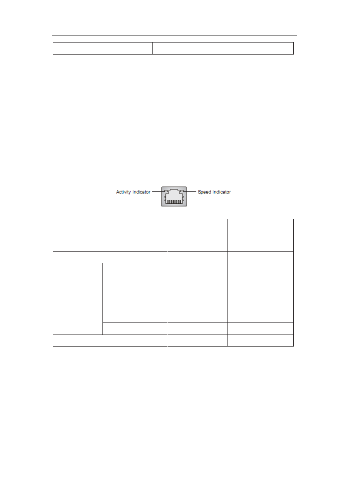
LAN
The standard RJ-45 LAN jack is for connection to the Local Area Network
(LAN). You can connect a network cable to it.
Left LED
(Active LED)
Right LED
(100M/1000M
Speed LED)
LED Color
Yellow
Green/Orange
10M Cable
Plug-in
No Transmission
Yellow (Lighting)
OFF
Transmission
Yellow (Blinking)
OFF
100M Cable
Plug-in
No Transmission
Yellow (Lighting)
Green (Lighting)
Transmission
Yellow (Blinking)
Green (Lighting)
1000M Cable
Plug-in
No Transmission
Yellow (Lighting)
Orange (Lighting)
Transmission
Yellow (Blinking)
Orange (Lighting)
In S3/S4/S5 Standby State
Yellow (Lighting)
OFF
Audio Jack
Line-In (Blue) - for external CD player or other audio devices
Line-Out (Green) - for speakers or headphones
Mic-In (Pink) - for microphones
Chapter 2 Hardware Setup
15
Connector
Serial ATA Connector: SATA1 ~ SATA2
This connector is a high-speed Serial ATA interface port. Each connector can
connect one Serial ATA device.
Important
Please do not fold the Serial ATA cable into a 90-degree angle. Otherwise,
data loss may occur during transmission.
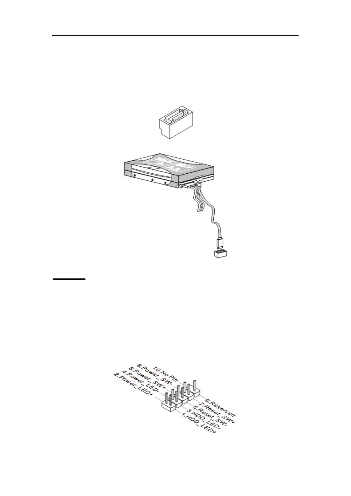
Front Panel Pinheader: JFP1
This front panel connector is provided for electrical connection to the front
panel switches & LEDs and is compliant with Intel Front Panel I/O
Connectivity Design Guide.
Chapter 2 Hardware Setup
16
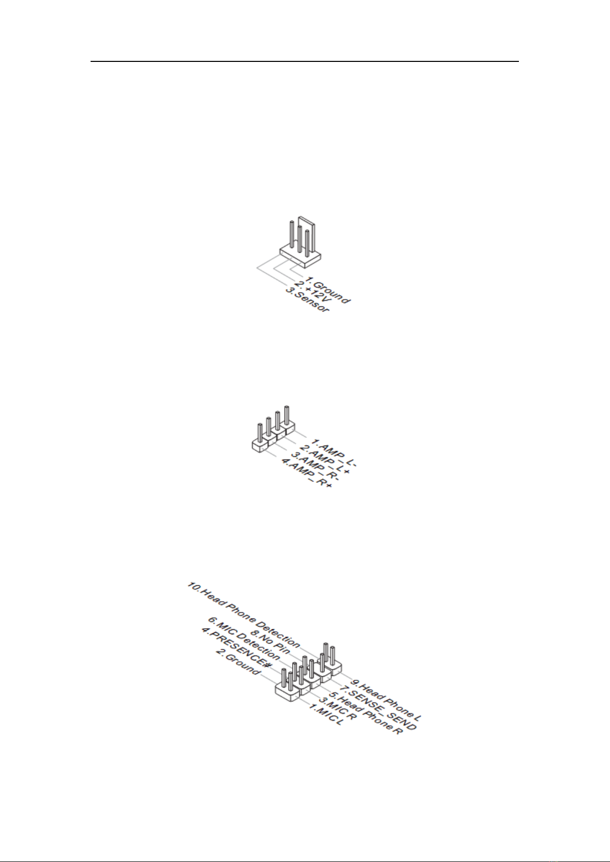
Fan Power Connector: SYSTEM_FAN1
The fan power connector supports system cooling fan with +12V. When
connecting the wire to the connectors, always note that the red wire is the
positive and should be connected to the +12V; the black wire is Ground and
should be connected to GND. If the mainboard has a System Hardware
Monitor chipset onboard, you must use a specially designed fan with speed
sensor to take advantage of the fan control.
Audio Amplifier Pinheader: JAMP1
The JAMP1 is used to connect audio amplifiers to enhance audio
performance.
Front Audio Pinheader: JAUD1
This connector allows you to connect the front panel audio and is compliant
with Intel Front Panel I/O Connectivity Design Guide.

Chapter 2 Hardware Setup
17
Front USB Pinheader: JUSB1, JUSB2
This connector, compliant with Intel I/O Connectivity Design Guide, is ideal for
connecting high-speed USB interface peripherals such as USB HDD, digital
cameras, MP3 players, printers, modems and the like.
Note that the pins of VCC and GND must be connected correctly to avoid
possible damage.
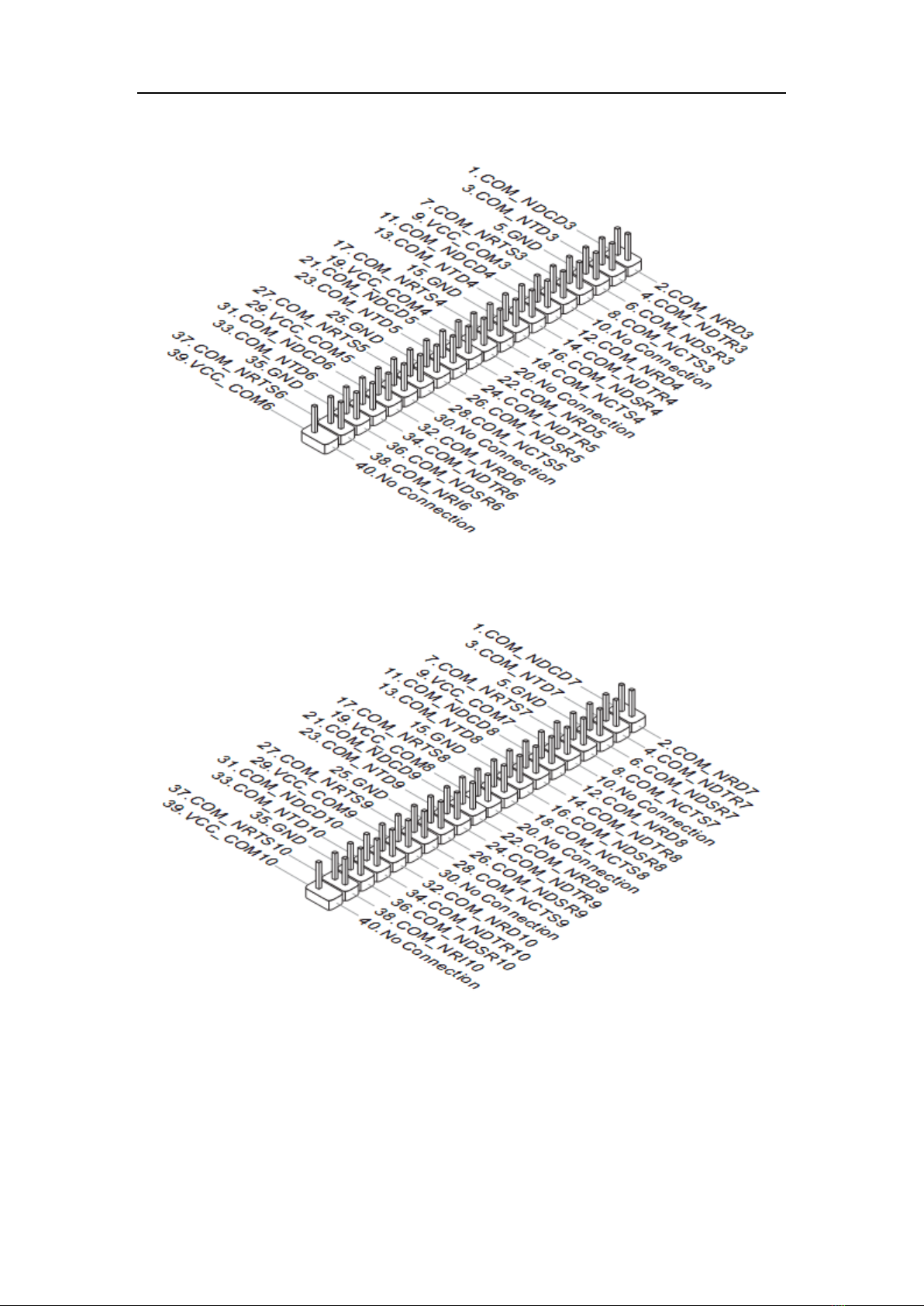
RS-232 Serial Port Pinheader: JCOM1, JCOM3
This connector is a 16550A high speed communications port that sends/
receives 16 bytes FIFOs. You can attach serial devices to it through the
optional serial port bracket.
Chapter 2 Hardware Setup
18
JCOM1
JCOM3
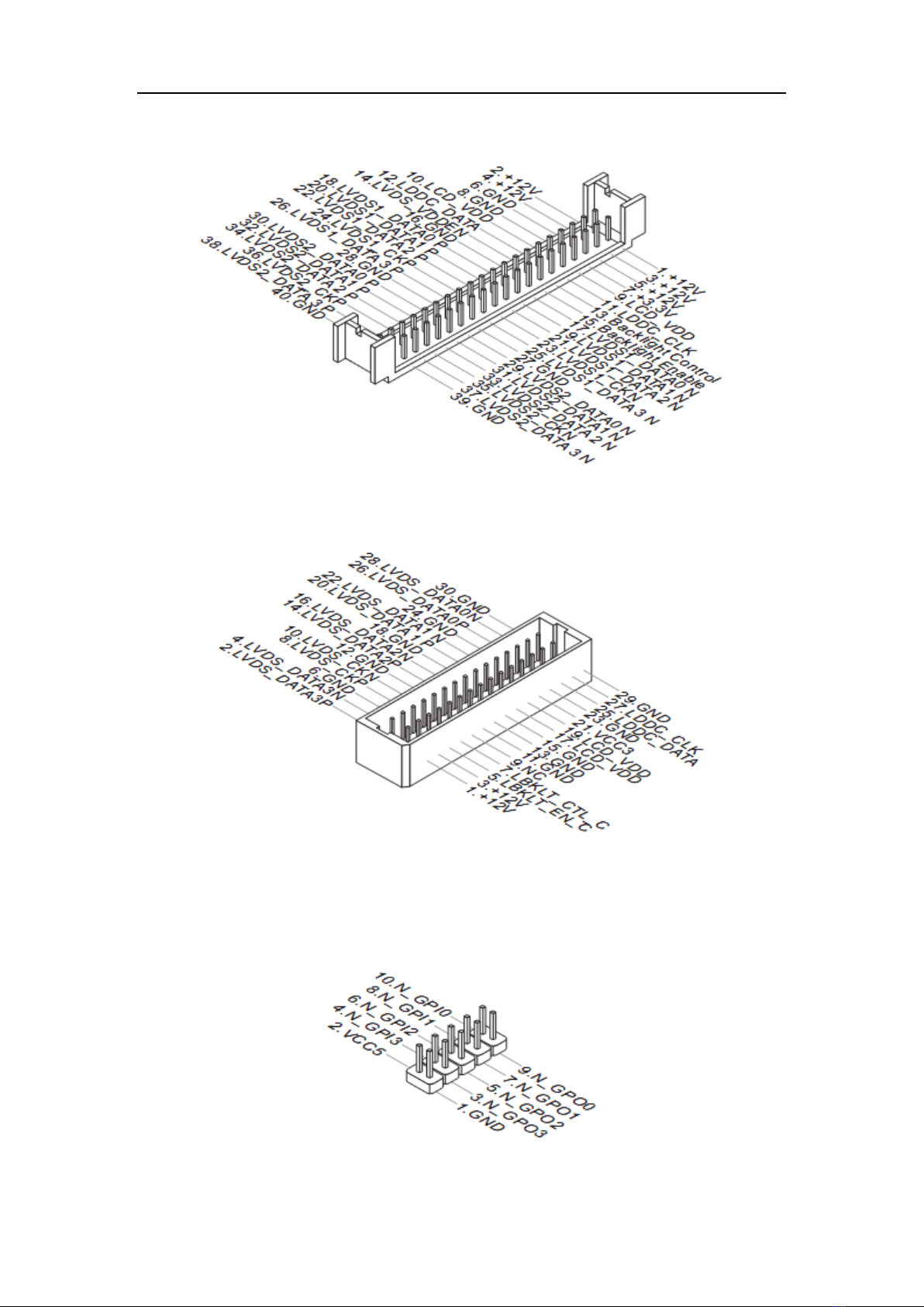
LVDS Connector: JLVDS1, JLVDS2
The LVDS (Low Voltage Differential Signal) connector provides a digital
interface typically used with flat panels. After connecting an LVDS interface
flat panel to this connector, be sure to check the panel datasheet and set the
JVDD1 jumper to proper power voltage.
Chapter 2 Hardware Setup
19
JLVDS2
JLVDS1
GPIO Connector: J1
This connector is provided for the General-Purpose Input / Output (GPIO)
peripheral module.
Table of contents
Other Nematron Motherboard manuals


