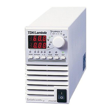
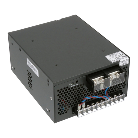
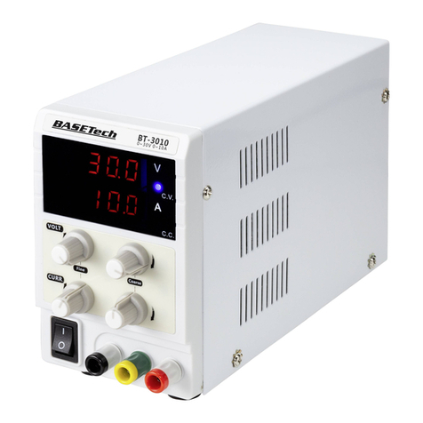
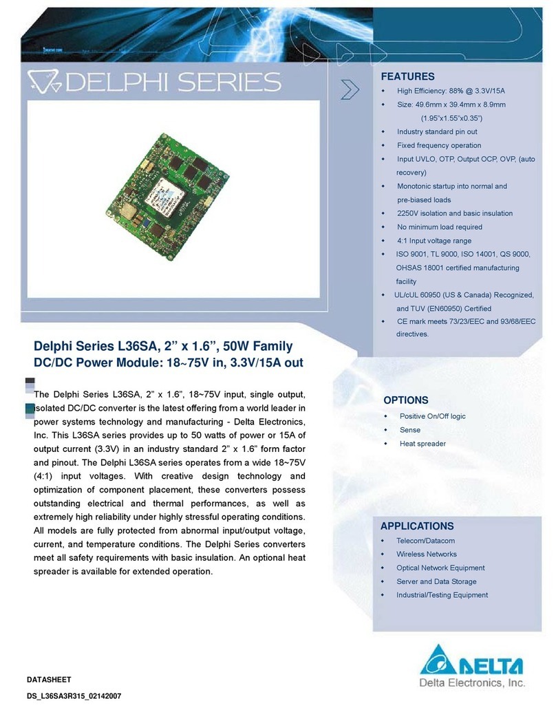
Nemic-Lambda SWS50 Series User manual

NEMIC-LAMBDA
SWS 50
⋅
75
⋅
100
⋅
150 Series
INSTRUCTION MANUAL
SWS50
⋅
75
⋅
100
⋅
150 Series
Instruction Manual
BEFORE USING THE POWER SUPPLY UNIT
Pay attention to all warnings and cautions before using the unit. Incorrect usage could lead to an electrical
shock, damage to the unit or a fire hazard.
WARNING and CAUTION
Do not modify.
Do not touch the internal components, they may have high voltage or high temperature. You may get electri-
cal shock or burned.
When the unit is operating, keep your hands and face away from it, you may get injured by an accident.
This power supply is primarily designed and manufactured to be used and enclosed in other equipment. Stick
the WARNING label for users on the system equipment and describe the notice in the instruction manual.
Never operate the unit under over current or shorted conditions for 30 seconds or more and out of Input volt-
age range in specification, which could result in damage or insulation failure. There is no possibility for fire
or burning.
Confirm connections to input/output terminals are correct as indicated in the instruction manual.
Do not drop or apply shock to power supply unit.
Note: CE MARKING
CE Marking, when applied to a product covered by this handbook indicates compliance with the low voltage
directive (73/23/EEC) as modified by the CE Marking Directive (93/68/EEC) in that it is complies with
EN60950
NEMIC-LAMBDA
SWS 50
⋅
75
⋅
100
⋅
150 Series
INSTRUCTION MANUAL
DWG NO. : CA732-04-01
APPD CHK DWG

1
NEMIC-LAMBDA
SWS 50
⋅
75
⋅
100
⋅
150 Series
INSTRUCTION MANUAL
1. Terminal Explanation
SWS50, SWS75
(1) +V : + Output terminal
(2) - V : - Output terminal
(3) FG : Functional Ground
(4) L : Input terminal Live line (Fuse in line)
(5) N : Input terminal Neutral line
(6) Output voltage adjustment trimmer
(7) Output monitoring indicator (Green LED)
SWS100, SWS150
(1) +V : + Output terminal
( 20A max./ terminal)
(2) -V : - Output terminal
( 20A max./ terminal)
(3) FG
: Functional Ground
(4) L : Input terminal Live line(Fuse in line)
(5) N : Input terminal Neutral line
(6) Output voltage adjustment trimmer
(7) Output monitoring indicator (Green LED)
2. Terminal connecting method
Input must be off when making connection.
Connect FG terminal to ground terminal of the
equipment.
Output current of each terminal pin of SWS150
must be less than 20A.
The output load line and input line shall be sepa-
rated and twisted to improve noise sensitivity.
Remote sensing lines shall be twisted or use
shielded wire.
SWS50, SWS75
LOAD+
-
SWS100, SWS150
Maximum output current of each output terminal is 20A.
If more than 20A, use 2 terminals.
+
-
LOAD

2
NEMIC-LAMBDA
SWS 50
⋅
75
⋅
100
⋅
150 Series
INSTRUCTION MANUAL
3. Explanation of Functions and Precautions
3-1. Input Voltage Range
Input voltage range is single phase 85 ~ 265VAC ( 47 ~
63Hz ) or 120 ~ 330VDC. Input voltage which is out of
specification may cause unit damage.For cases where con-
formance to various safety specs(UL,CSA,EN) are re-
quired,input voltage range will be 100~240VAC ( 50/60Hz ).
3-2. Output Voltage Range
V.ADJ trimmer is for output voltage adjustment within the
range of specifications.To turn the trimmer clockwise, the
output voltage will be increased. Note over voltage protec-
tion ( OVP ) function may trigger if the output voltage is in-
creased excessively.
3-3. Inrush Current
Power Thermistor is built in to protect the circuit from In-
rush Current. Please carefully select input switch and fuse in
cases of the high temperature and re-input the power.
3-4. Over Voltage Protection (OVP)
The OVP function ( Inverter shut down method, manual re-
set type ) is provided. When OVP triggers, the output will be
shut down. The input shall be removed for a few minutes,
and then re-input for recovery of the output. OVP setting is
fixed and not to be adjusted externally.
3-5. Over Current Protection (OCP)
Current limiting, automatic recovery. OCP function operates
when the output current exceeds OCP specifications. The
output will be automatically recovered when the overload
condition is canceled. Do not operate overload or dead short
conditions for more than 30 seconds, which could result in
damage or insulation failure.
3-6. Output Ripple & Noise
Ripple & noise are measured at 20MHz by using a 12’’
twisted pair terminated with a 0.1uF & 47uF capacitor.
When load lines are longer, ripple will become larger. In this
case, electrolytic capacitor, film capacitor, etc. might be nec-
essary to use across the load terminal. The output ripple
cannot be measured accurately if the probe ground lead of
oscilloscope is too long.
3-7. Series Operation
For series operation, either method ( A ) or ( B ) is pos-
sible.
Method ( A )
Output
Terminal
Output
Terminal
Load
Power
Supply
Method ( B )
Power
Supply
Load
Load
Output
Terminal
Output
Terminal
3-8. Parallel Operation
(A) Operation to increase the Output Current is not
possible.
Load
Output
Terminal
Output
Terminal
Power
Supply

3
NEMIC-LAMBDA
SWS 50
⋅
75
⋅
100
⋅
150 Series
INSTRUCTION MANUAL
(B) Operation as a Backup Power Supply is possible as fol-
lows.
1. Set the power supply output voltage higher by the
amount of forward voltage drop ( Vf ) of the diode.
2. Please adjust the output voltage of each power supply
to be the same.
3. Please use within the specifications for output voltage
and output current.
Output
Terminal
Output
Terminal
Load
Power
Supply
4. Isolation / Withstand Voltage
4-1. Isolation Test
Isolation resistance between output and FG ( chasis ) shall
be more than 100MΩat 500VDC. For safety, voltage setting
of DC isolation tester must be done before the test. Ensure
that the it is fully discharged after the test.
Output ~ FG (chassis)
AC(L)
AC(N)
FG
+
+
-
-
Isolation
Tester
500VDC, 100MΩormore
4-2. Withstand Voltage
This series is designed to withstand 3.0kVAC between input
and output, 2.0kVAC between input and FG ( chassis ) and
500VAC between output and FG ( chassis ) each for 1 min-
ute. When testing withstand voltage, set current limit of
withstand voltage test equipment at 20mA ( Output-FG
( chassis ) : 100mA ). The applied voltage must be gradually
increased from zero to testing value and then gradually de-
creased for shut down. When timer is used, the power
supply may be damaged by high impulse voltage at
timer switch on and off. Connect input and output as
follows.
Input ~ FG( chassis ) : solid line
2kVAC, 1min ( 20mA )
Input ~ Output : dotted line
3kVAC, 1min ( 20mA )
AC(L)
AC(N)
FG
+
+
-
-
Withstand
Voltage
Tester
Output ~ FG ( chassis )
500VAC, 1min ( 100mA )
AC(L)
AC(N)
FG
+
+
-
-
Withstand
Voltage
Tester
5. Mounting Directions
5-1. Output Derating according to the Mounting
Directions
Recommend standard mounting is method ( A ).
Method ( B ) ( C ) and ( D ) are also possible. Refer to
the derating below. Please do not use installation
method ( E ), where the PCB will be on the topside and
heat will be trapped inside the unit. In the following
derating curve, the maximum output current is consid-
ered to be 100%.

4
NEMIC-LAMBDA
SWS 50
⋅
75
⋅
100
⋅
150 Series
INSTRUCTION MANUAL
Standard Mounting ( A )
*For SWS100 and SWS150,mounting (D) is not possible.
Output Derating
(A) Convection cooling
SWS50-5, 12, 24
100
-10 0 10 20 30 40 50 60 7
0
80
60
40
20
0
Ambient Temperature (°C)
(%)
Out
p
ut Current
A
B,C,D
SWS75-5
100
-10 0 10 20 30 40 50 60 7
0
80
60
40
20
0
Ambient Temperature (°C)
(%)
Out
p
ut Current
A
B,C,D
SWS75-12,24
100
-10 0 10 20 30 40 50 60 7
0
80
60
40
20
0
Ambient Temperature (°C)
(%)
Out
p
ut Current
A
B,C,D
SWS100-5, 12, 24
100
-10 0 10 20 30 40 50 60 7
0
80
60
40
20
0
Ambient Temperature (°C)
(%)
Out
p
ut Current
A
B,C
SWS150-5
100
-10 0 10 20 30 40 50 60 7
0
80
60
40
20
0
Ambient Temperature (°C)
(%)
Out
p
ut Current
A
B,C
SWS150-12,24
(B)
(C) (D) (E)
N
ot Possible

5
NEMIC-LAMBDA
SWS 50
⋅
75
⋅
100
⋅
150 Series
INSTRUCTION MANUAL
100
-10 0 10 20 30 40 50 60 7
0
80
60
40
20
0
Ambient Temperature (°C)
(%)
Out
p
ut Current
A
B,C
(B) Force air cooling
Recommended minimum air velocity is 1.2m/s,flow
through the component side of power supply.
SWS75-5, 12, 24
100
-10 0 10 20 30 40 50 60 7
0
80
60
40
20
0
Ambient Temperature (°C)
(%)
Out
p
ut Current
A,B,C,D
SWS100 – 5, 12, 24
SWS150 – 5, 12, 24
100
-10 0 10 20 30 40 50 60 7
0
80
60
40
20
0
Ambient Temperature (°C)
(%)
Out
p
ut Current
A,B,C
5-2 Mounting Method
1) This is convection cooling type power supply. In
the consideration for the heat radiation and safety.
Please keep a distance more than 15mm between
the power supply and the peripheral parts. When
lining up multiple units, please make sure to place
them 15mm or more apart from each other.
2) The maximum allowable penetration of mounting
screws is 6mm.
3) Recommended torque for mounting screw
SWS50, SWS75 (M3 screw) : 0.49 N⋅m
( 5.0 kgf⋅cm )
SWS100, SWS150(M4 screw) : 1.27 N⋅m
( 13.0 kgf⋅cm )
6. Wiring Method
The output load line and input line shall be
separated and twisted to improve noise sensitivity.
Use all lines as thick and short as possible to
make lower impedance.
Noise can be eliminated by attaching a capacitor
to the load terminals.
In SWS150, the output current of each output
terminal is limited to 20A. When it is more than
20A, please use 2 terminals together.
For safety and EMI considerations, connect the
FG terminal of SWS series to mounting set
ground terminal.
The recommended torque for the terminal piece:
(M3.5 Screws) : 0.74N⋅m
(7.5kgf⋅cm )
Air flow
Sheet Metal
15mm or more
Provide punching, etc. to allow air to pass.
15mm or more

6
NEMIC-LAMBDA
SWS 50
⋅
75
⋅
100
⋅
150 Series
INSTRUCTION MANUAL
7. External Fuse Rating
Refer to the following fuse rating when selecting the exter-
nal fuses that are to be used on input line. Surge current
flows when line turns on. Use slow-blow fuse or time-lag
fuse. Do not use fast-blow fuse. Fuse rating is specified by
in-rush current value at line turn-on. Do not select the fuse
according to input current (rms.) values under the actual
load condition.
SWS50, SWS100 : 3.15A
SWS75, SWS150 : 5A
8. Before concluding that the unit is at fault…
Before concluding that the unit is at fault, make the follow-
ing checks.
Check if the rated input voltage is connected.
Check if the wiring of input and output is correct.
Check if the wire material is not too thin.
Check if the output voltage control (V.ADJ) is properly
adjusted.
Check if the output current and output wattage dose not
over specification.
Audible noise can be heard during Dynamic-Load
operation.
Audible noise can be heard when input voltage wave-
form is not sinusoidal wave.
9. Notes
1) Overvoltage Category II
2) Radio Interference Suppression Test is not per-
formed.
This manual suits for next models
3
Other Nemic-Lambda Power Supply manuals
Popular Power Supply manuals by other brands
Behringer
Behringer Micropower PS400 Technical specifications
Brooks Instrument
Brooks Instrument 0250 Series quick start guide

Elenco Electronics
Elenco Electronics XP-603 instruction manual
Assa Abloy
Assa Abloy Securitron AQD6 Series manual
Dell
Dell EU2SPE Disassembly instructions
Kikusui
Kikusui PAK10-300T instruction manual
