neobotix MMO-500 User manual

MMO-500
Neobotix GmbH
Apr 14, 2022

Contents:
1 MMO-500 1
1.1 Product Information ........................................... 2
1.1.1 Intended Use .......................................... 2
1.1.2 Improper Use .......................................... 2
1.1.3 Working Area .......................................... 2
1.1.4 Qualified Personnel ....................................... 2
1.1.5 Safety Instructions ....................................... 3
1.2 Operating Elements ........................................... 3
1.3 Arm .................................................... 3
1.3.1 Properties of the Universal Robots Arms ............................ 3
1.3.2 Standalone Operation ...................................... 3
1.4 Mechanical Properties .......................................... 3
1.4.1 Dimensions of the Robot .................................... 3
1.4.2 Dimensions of the Manipulator ................................. 5
1.5 Transport ................................................. 5
1.5.1 Unpacking and Assembly .................................... 5
1.5.2 Installing the Auxiliary Batteries ................................ 7
1.6 Taking out of Service ........................................... 7
1.7 Legal Notes ................................................ 8
1.7.1 EU Declaration of Incorporation ................................ 8
1.7.2 RoHS Information ....................................... 8
2 MPO-500 9
2.1 Product Information ........................................... 10
2.1.1 Intended Use .......................................... 10
2.1.2 Improper Use .......................................... 10
2.1.3 Working Area .......................................... 10
2.1.4 Qualified Personnel ....................................... 11
2.1.5 Safety Instructions ....................................... 11
2.2 Operating Elements ........................................... 12
2.2.1 Emergency Stop Buttons .................................... 12
2.2.2 Key Switch ........................................... 13
2.2.3 Brake Release Button ...................................... 13
2.2.4 Charging Socket ........................................ 13
2.2.5 LC-Display ........................................... 13
2.2.6 Access to the On-Board Computer ............................... 13
i

2.3 Mechanical Properties .......................................... 13
2.3.1 Dimensions ........................................... 13
2.3.2 Absolute Maximum Ratings .................................. 14
2.3.3 Positions of Sensors ....................................... 14
2.3.4 Electrical Properties and Miscellaneous Data ......................... 14
2.4 Transport ................................................. 16
2.4.1 Packaging ............................................ 16
2.4.2 Unpacking the Robot ...................................... 17
2.4.3 Short Distance Transport .................................... 17
2.4.4 Long Distance Transport .................................... 17
2.5 Maintenance ............................................... 17
2.5.1 Software ............................................. 17
2.5.2 Cleaning ............................................. 18
2.5.3 Batteries ............................................. 18
2.5.4 Battery Replacement (Quick Change) ............................. 18
2.5.5 Fuses .............................................. 19
2.6 Taking out of Service ........................................... 19
2.7 Legal Notes ................................................ 19
2.7.1 EU Declaration of Conformity ................................. 19
2.7.2 RoHS Information ....................................... 20
3 General Hardware Information 21
3.1 Key Switch ................................................ 21
3.1.1 Turning on ........................................... 21
3.1.2 Emergency Reset ........................................ 21
3.1.3 Shut down ............................................ 21
3.1.4 Switch off ............................................ 21
3.2 LC Display ................................................ 22
3.2.1 Main View ........................................... 22
3.2.2 The Info View .......................................... 23
3.3 Batteries ................................................. 24
3.3.1 Battery Types .......................................... 24
3.3.2 Charging ............................................ 25
3.3.3 Recycling ............................................ 26
3.4 Charging Stations ............................................ 26
3.4.1 Automatic Charging Station .................................. 26
3.4.2 External Battery Charging Station ............................... 28
3.5 Connectors ................................................ 30
3.5.1 TE Connectivity - HE14 .................................... 30
3.5.2 Würth Elektronik - MPC4 ................................... 30
3.5.3 Würth Elektronik - MPC3 ................................... 31
3.6 Safety Instructions ............................................ 32
3.6.1 General Safety Instructions ................................... 32
3.6.2 Briefing ............................................. 33
3.6.3 Safety System .......................................... 33
3.6.4 Cooperating with the Robot ................................... 34
3.6.5 Bringing into Service ...................................... 35
3.6.6 Modification of the System ................................... 35
3.6.7 Expected Misuse ........................................ 35
3.6.8 Configuring the Safety Fields .................................. 36
3.7 Safety Instructions (Manipulators) .................................... 37
3.7.1 Robot Arms ........................................... 37
3.7.2 Laser Scanners ......................................... 37
3.7.3 Working required from the Customer .............................. 37
ii

3.8 Maintenance ............................................... 38
3.8.1 Cleaning ............................................. 38
3.8.2 Maintenance and Repairs .................................... 38
3.9 Qualified Personnel ........................................... 39
3.10 Taking out of Service ........................................... 40
3.10.1 Disassembly ........................................... 40
3.10.2 Recycling ............................................ 40
3.10.3 Mechanical parts ........................................ 40
3.10.4 Electrical components ..................................... 40
3.10.5 Batteries ............................................. 41
3.11 Legal Notes ................................................ 41
3.11.1 Version Information ....................................... 41
3.11.2 Liability ............................................. 41
3.11.3 Downloads and Further Information .............................. 41
iii

CHAPTER 1
MMO-500
_
Download as PDF1
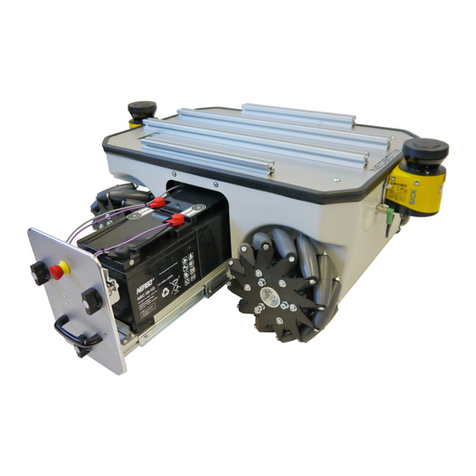
The mobile manipulator MMO-500 combines the omnidirectional robot MPO-500 (page 9) with a light-weight robot
arm, for example from Universal Robots.
Its Mecanum wheels allow the MMO-500 to move freely into any direction and thus to re-position the integrated arm
1https://neobotix-docs.de/hardware/en/MMO-500.pdf
1

CHAPTER 1. MMO-500 1.1. PRODUCT INFORMATION
very easily. This way the arm’s workspace is significantly enlarged without having to deal with any constraints and
kinematics problems.
The MMO-500 can integrate most of the available light weight arms. Due to its big footprint and high payload, the
MMO-500 is also capable of carrying the big Universal Robots arm UR10 which can handle loads up to 10 kg.
The platform’s movement can be controlled by the free Robot Operating System. The Universal Robots arm, like
most suitable robot arms, can be configured with its original control software and manual control unit and connected
to ROS.
1.1 Product Information
1.1.1 Intended Use
The MMO-500 has been designed for use in service robotics research. It can be used for a wide range of different
experiments and tests in fields such as autonomous vehicles, mobile manipulation and factory automation.
The MMO-500 may only be used in laboratories, test halls or similar environments. It is not recommended to use the
MMO-500 in any other surrounding, especially not outdoors, in offices or factories.
1.1.2 Improper Use
Danger:
• The mobile robot must not be used for transportation of passengers in any way. No person must ride on the
robot itself, nor must the robot be used to move any other vehicle or hanger with passengers aboard.
• The mobile robot must not be operated in any publicly accessible area without safety assessment. If the
robot is to be modified either permanently (e.g. by mounting additional components) or temporarily (e.g. by
loading cargo) its safe operation must be assessed and approved.
• Without the safety approval described above, the mobile robot must at no times be used without supervision
of a qualified operator if there are guests, passers-by or other people unfamiliar with the robot within the
working area.
• The robot must never be operated in areas where there are staircases leading down, elevated platforms or
other possibilities for falling or dropping down. This may cause serious injuries or death!
1.1.3 Working Area
The same conditions as for the MPO-500 apply and can be found at Product Information (page 10) .
1.1.4 Qualified Personnel
This product must only be modified, commissioned, operated and serviced by qualified personnel.
The requirements on qualified personnel can be found at Qualified Personnel (page 39).
2

CHAPTER 1. MMO-500 1.2. OPERATING ELEMENTS
1.1.5 Safety Instructions
Please refer to the safety instructions for the MPO-500 which can be found at Safety Instructions (page 11).
Additionally, refer to Safety Instructions (Manipulators) (page 37).
1.2 Operating Elements
Please refer to the corresponding page for the MPO-500: Operating Elements (page 12).
1.3 Arm
1.3.1 Properties of the Universal Robots Arms
The UR robot arm has not been modified. All features and properties of the arm remain unchanged as stated in the
manufacturer’s documentation. Please refer to this documentation for further information.
The platform’s emergency stop system was integrated into the arm’s safety system as external machine. Technical
details on this connection can be found in the electrical circuit diagram of the MMO-500 and in the operating manual
of the robot arm. In case the arm is to be operated separately this connection has to be bridged with the Harting
connector that was included in delivery. Please see the following chapter for details.
Tip: The configurable inputs CI0 and CI1 have been changed to “Unassigned”. The configurable outputs CO0 and
CO1 have been set to “Emergency stop”. The safety configuration password was set to neobotix. Please contact
Neobotix if you have any questions concerning the safety system.
1.3.2 Standalone Operation
The mobile platform can be operated without switching on the arm or completely without arm. To do so please plug
in the bridging connector -X31 instead of the cable to the UR arm controller. This connector can be found at the front
left of the platform’s top plate.
The robot arm can be operated independently of the mobile platform if the corresponding bridging connector -X31 is
connected to the cable leading to the controller box.
Additionally another connector has to be replaced inside the controller box to make the safety system of the arm inde-
pendent of the platform’s power supply. This grey bridging connector replaces the green one required for combined
operation.
When operating the arm without the platform it is recommended to power it from an ordinary 230V power outlet and
not from the mobile robot’s integrated DC/AC inverter.
Please check the robot arm’s operating manual for details on the power requirements.
1.4 Mechanical Properties
1.4.1 Dimensions of the Robot
See Dimensions (page 13).
3

CHAPTER 1. MMO-500 1.4. MECHANICAL PROPERTIES
Fig. 1: Connector -X31
Fig. 2: Power Connector for Standalone Operation
4

CHAPTER 1. MMO-500 1.5. TRANSPORT
1.4.2 Dimensions of the Manipulator
Fig. 3: Dimensions of the MMO-500 UR10
All dimensions are in millimetres.
Description Symbol Value
Height of the mounting plane H1 386
Height of the control cabinet’s to plate H2 805
Offset between arm base and platform centre O 205
Distance to the front of the cabinet L1 115
Length of the cabinet’s top plate L2 496
Width of the cabinet’s top plate W 550
1.5 Transport
Note: The corresponding conditions of the MPO-500 also apply and can be found at Transport (page 16).
1.5.1 Unpacking and Assembly
The mobile robot MMO-500 is packed in a rugged wooden box which can be reused for future transports.
Carefully lift the control cabinet onto the platform’s top plate and position it as shown in the figure below. Make sure
that the front of the cabinet’s base plate is flush with the front of the inner aluminium profiles on the platform’s top
plate.
5

CHAPTER 1. MMO-500 1.5. TRANSPORT
Fig. 4: Controller cabinet and robot arm mounted to mobile platform
6

CHAPTER 1. MMO-500 1.6. TAKING OUT OF SERVICE
Now fasten the control cabinet to the mobile platform using the counter sunk screws that were included in delivery.
The cover plates at the front and the sides of the control cabinet (marked in red in the figure) can be removed to provide
easy access to the inside of the cabinet.
Connect the cables inside the control cabinet to the appropriate plugs of the mobile platform. Please see the electrical
circuit diagram for details.
If the robot arm was shipped separately, position it on top of the control cabinet as shown above. Then fasten it securely
using the M8 screws included in the delivery. Finally plug the robot arm’s cable into the socket at the underside of the
controller box.
1.5.2 Installing the Auxiliary Batteries
In order to extend the robot’s uptime, a second battery pair can be installed into the controller cabinet.
Before installing the auxiliary batteries, please turn off the robot and fully charge both the batteries that are currently
used in the robot as well as the additional battery pack.
Remove the front plate of the controller cabinet and place the batteries inside the aluminium frame on the cabinet’s
base plate, with the battery cables facing into the cabinet.
Fig. 5: Position of the auxiliary batteries
Danger: When the auxiliary batteries are in use, the robot must only be recharged by connecting the battery
charger to the robot manually or by using the automatic charging station. Do not recharge either pair of batteries
individually by connecting them to the battery charger directly.
Two regular ATO fuses (32V) inside the cabinet protect the electrical systems from excessive currents.
1.6 Taking out of Service
You can find information about taking out of service and about recycling here (page 40).
7

CHAPTER 1. MMO-500 1.7. LEGAL NOTES
1.7 Legal Notes
The general legal notes can be found at Legal Notes (page 41).
1.7.1 EU Declaration of Incorporation
This product is a partly completed machinery and sold without CE marking.
This partly completed machinery must not be put into service until the final machinery into which it is to be incor-
porated has been declared in conformity with the provisions of Directive 2006/42/EC and all other applicable EU
directives.
1.7.2 RoHS Information
As non-road mobile machinery our mobile robots are explicitly exempted from the scope of the RoHS directive
2011/65/EU. We have nevertheless followed the underlying principles of RoHS and tried to reduce the use of harmful
and dangerous substances in our products as much as possible.
8

CHAPTER 2
MPO-500
_
Download as PDF2
The mobile robot MPO-500 features four Mecanum wheels which provide an extraordinary manoeuvrability. Each
Mecanum wheel has several independent rollers mounted along its circumference. The axles of the rollers are rotated
at 45° to the wheel’s main axle. This design enables the robot to instantly move into any direction: The Mecanum
wheels make it truly omnidirectional.
This kinematics offers a number of interesting advantages over other systems like Omni wheels or the Omni Drive
Modules of the MPO-700:
• Mecanum wheels have proven themselves worldwide since 1973,
• they require only a very simple and robust drive system,
• they allow instantaneous motion without alignment and
• the required control software is very simple.
2https://neobotix-docs.de/hardware/en/MPO-500.pdf
9

CHAPTER 2. MPO-500 2.1. PRODUCT INFORMATION
These extraordinary features have made Mecanum wheels a very popular solution especially in robotics research.
2.1 Product Information
2.1.1 Intended Use
The MPO-500 has been designed for use in service robotics research. It can be used for a wide range of different
experiments and tests in fields such as autonomous vehicles, mobile manipulation and factory automation.
Depending on the intended application the MPO-500 can be used on its own, in combination with other robot vehicles
and in combination with stationary systems. Furthermore, application specific extensions can be integrated into the
basic platform. These might be a customised cargo area, a robot arm or special sensors.
The MPO-500 may only be used in laboratories, test halls or similar environments. It is not recommended to use the
MPO-500 in any other surrounding, especially not outdoors, in offices or factories.
2.1.2 Improper Use
Danger:
• The mobile robot must not be used for transportation of passengers in any way. No person must ride on the
robot itself, nor must the robot be used to move any other vehicle or hanger with passengers aboard.
• The mobile robot must not be operated in any publicly accessible area without assessment of risks. If the
robot is to be modified either permanently (e.g. by mounting additional components) or temporarily (e.g. by
loading cargo) its safe operation must be assessed and approved.
• Without the safety approval described above, the mobile robot must at no times be used without supervision
of a qualified operator if there are guests, passers-by or other people unfamiliar with the robot within the
working area.
• The robot must never be operated in areas where there are staircases leading down, elevated platforms or
other possibilities for falling or dropping down. This may cause serious injuries or death!
2.1.3 Working Area
The working area of the mobile robot must be protected against rain and have a sufficiently firm and clean floor. The
floor must be even and horizontal.
Tip: Slopes, edges, steps and unevenness can result in problems when the robot is moving or with the localisation.
Under some circumstances the robot might not be able to continuously determine its exact position and therefore might
plan unnecessary or problematic paths or might even be unable to reach its destination.
Under certain conditions, rain or heavy splash water might enter the robot and cause damages. Flying sparks, heavy
dust and similar dirt may affect or damage the sensors and thus might make the operation of the mobile robot inefficient
or unsafe. Dirt and liquids on the floor may lead to slippage and problems of localisation and navigation.
The robot does not feature any sensor for detecting staircases, holes or other areas where it may drop down. In case of
loss of localisation or faulty programming the robot might fall down such place
10

CHAPTER 2. MPO-500 2.1. PRODUCT INFORMATION
Warning: Always check for and secure all places where the robot might drop down before bringing it into
operation.
2.1.4 Qualified Personnel
This product must only be modified, commissioned, operated and serviced by qualified personnel.
The requirements on qualified personnel can be found at Qualified Personnel (page 39).
2.1.5 Safety Instructions
Please also check the general safety instructions for Neobotix robots which can be found at Safety Instructions
(page 32).
2.1.5.1 Danger Areas
Wheels
Due to their unique design, the four Mecanum wheels of the MPO-500 have a higher potential for danger than normal
wheels. Please mind the following in order to prevent injuries or damages:
• Never touch the wheels of the moving robot and also prevent guests, passers-by and especially children from
touching them.
• Take care that no part of the cargo or additional components (e.g. cables, wires) can touch the wheels.
• Make sure that the working space of the MPO-500 is free of all objects which might be caught in the wheels.
Different from normal wheels Mecanum wheels may not only run over objects but objects might also get stuck
in the wheels and might be moved along.
• In case additional safety measures are required please contact Neobotix. We will provide wheel housings de-
signed for your application.
Battery Drawer
Both the outsides of the robot and the battery drawer are completely safe to touch while the robot is in use. Neverthe-
less, opening the battery drawer allows one to reach into the robot platform and to touch powered components.
Warning: Never reach into the robot platform while the system is turned on. There is risk of electric shock!
All cables and wires on the batteries and inside the drawer are placed and cut to length in a way that will prevent
damages during normal operation. Modifying or moving these parts might cause damage to the wires.
Warning: Always take great care that no cables are clamped between drawer and platform or get caught in the
telescopic slides. Please contact Neobotix immediately when noticing any damages to the cables.
A robot with damaged battery cables must not be operated in any case!
11

CHAPTER 2. MPO-500 2.2. OPERATING ELEMENTS
Laser Scanner Positions
The height of the scanning plane of the laser scanners must be chosen according to the applications safety require-
ments. In case the robot is to operate fully autonomously and without supervision in an area where it might encounter
unconscious people the scanning plane should be no more than 200 mm above the ground.
Each laser scanner has a 270° wide field of view which is symmetric to the scanner housing. Therefore the positions
of the laser scanners must also be chosen in consideration of blind spots.
Please contact Neobotix if the positions of the laser scanners has to be modified.
2.2 Operating Elements
The figure below shows the tail of the MPO-500 and the most important operating elements.
Fig. 1: Operating elements of the MPO-500
1 Emergency stop buttons
2 Brake release button
3 Key switch
4 HDMI socket
5 Wireless joystick receiver
6 Charging socket
7 Connector for 2nd scannerr
8 Ethernet socket
9 USB socket
10 LC-Display
2.2.1 Emergency Stop Buttons
When one of these buttons is pressed the robot is immediately set to emergency stop. All drives are disconnected from
power supply and the fail-safe brakes are engaged. This state can be reset by unlocking the emergency stop buttons
12

CHAPTER 2. MPO-500 2.3. MECHANICAL PROPERTIES
and turning the Key Switch (page 21) clockwise to position II for a few seconds.
2.2.2 Key Switch
See Key Switch (page 21).
2.2.3 Brake Release Button
Pressing this button will open the motors’ brakes allowing the robot to be moved even while it is turned off.
2.2.4 Charging Socket
The battery charger can be manually connected to this socket. Further information can be found at Charging (page 25).
2.2.5 LC-Display
This display shows the most important status information.
A detailed description of the LCD can be found in LC Display (page 22).
2.2.6 Access to the On-Board Computer
An HDMI socket, a USB socket and an Ethernet port can be used to work on the computer and to prepare the robot
for the next application.
2.3 Mechanical Properties
2.3.1 Dimensions
Description Symbol Value (mm)
Wheel diameter D 254
Ground clearance G 45
Height of the mounting plane H1 386
Height of the scanner cover H2 409
Overall length of platform L1 988
Length of inner aluminium profiles L2 680
Length of outer aluminium profiles L3 380
Distance from platform centre to wheel axes L4 250
Maximum length to platform centre L5 494
Width of top plate W1 500
Distance from platform centre to outer aluminium profiles W2 219
Distance from platform centre to inner aluminium profiles W3 73
Track width W4 548
Maximum width W5 662
Size of aluminium profiles P 30
13

CHAPTER 2. MPO-500 2.3. MECHANICAL PROPERTIES
Fig. 2: Dimensions of the MPO-500
2.3.2 Absolute Maximum Ratings
Warning: Exceeding these ratings might cause malfunctions or damage the robot!
Description Units Value
Storage temperature °C -20 .. +50
Operating temperature (environmental temperature) °C +0 .. +35
Payload (equally distributed to aluminium profiles, default version) kg 80
Payload (equally distributed to aluminium profiles, high payload version) kg 250
Maximum speed m/s 0.9
Maximum bumpiness to pass over mm 5
Maximum acceleration m/s22.4
2.3.3 Positions of Sensors
All distances are in millimetres, measured relative to the platform’s coordinate system. All angles are in degrees,
measured counter-clockwise from the driving direction.
Sensor Symbol X-pos. Y-pos. Z-pos. a-angle b-angle
Front laser scanner LS1 442 0 372 0 0
Rear laser scanner LS2 -442 0 372 0 180
2.3.4 Electrical Properties and Miscellaneous Data
2.3.4.1 Properties of Internal Components
All data are taken from the respective data sheets.
14

CHAPTER 2. MPO-500 2.3. MECHANICAL PROPERTIES
Fig. 3: Coordinate system of MPO-500
Fig. 4: Positions of the laser scanners
15

CHAPTER 2. MPO-500 2.4. TRANSPORT
Description Units Value
Motor power W 300
Rated motor speed rpm 3000
Maximum motor speed rpm 5000
Possible motor speed (at battery voltage) rpm 1800
Rated motor torque Nm 0.95
Maximum motor torque Nm 1.91
Brake torque (static) Nm 1.47
Encoder resolution Increments/Revolution 10000
Gear ratio 1 25:1
Rated battery voltage V 24
Maximum unregulated voltage V 29
Battery capacity Ah 50
2.3.4.2 Metering Capacities of Sensors
All data are taken from the respective datasheets. Distances are measured in meters, angles are measured in degree.
Sensor Resolution Min.range Max. range Hor. angle Vert. angle
Laser scanner 0.5° 0 30 ±135 0
Ultrasonic sensors ~±0.01 m 0.25 1.5 ±60 ±30
2.3.4.3 Other Properties
Description Units Value
Weight kg 80
Expected working time a 10
2.3.4.4 Connectors
See chapter Connectors (page 30).
2.4 Transport
2.4.1 Packaging
The mobile robot MPO-500 is packed in a rugged wooden box which can be reused for future transports. If the original
box cannot be used anymore it is recommended to build a new box of similar design.
The base plate of the box has to be strong enough to carry the robot and to take asymmetric forces, e.g. when
moving the box with a forklift. When packing the robot it has to be secured against unintended slipping by sufficient
cushioning. In order to prevent dust and dirt from the cushioning material to enter the robot, the maintenance opening
should be closed and all connectors should be fastened or covered prior to packing the robot.
Tip: Depending on the cushioning material it might be advisable to protect the brake release button against unintended
activation. If this button is pressed during transport, the robot may move inside the box and the batteries might get
16
Other manuals for MMO-500
1
Table of contents
Other neobotix Robotics manuals
