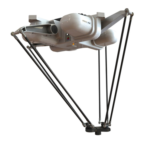
neobotix MMO-500 User manual

MMO-500
Neobotix GmbH
Feb 25, 2022

Contents:
1 MMO-500 1
1.1 Product Information ........................................... 2
1.1.1 Intended Use .......................................... 2
1.1.2 Improper Use .......................................... 2
1.1.3 Working Area .......................................... 2
1.1.4 Qualified Personnel ....................................... 2
1.1.5 Safety Instructions ....................................... 3
1.2 Operating Elements ........................................... 3
1.3 Arm .................................................... 3
1.3.1 Properties of the Universal Robots Arms ............................ 3
1.3.2 Standalone Operation ...................................... 3
1.4 Mechanical Properties .......................................... 3
1.4.1 Dimensions of the Robot .................................... 3
1.4.2 Dimensions of the Manipulator ................................. 5
1.5 Transport ................................................. 5
1.5.1 Unpacking and Assembly .................................... 5
1.5.2 Installing the Auxiliary Batteries ................................ 7
1.6 Taking out of Service ........................................... 7
1.7 Legal Notes ................................................ 8
1.7.1 EU Declaration of Incorporation ................................ 8
1.7.2 RoHS Information ....................................... 8
2 General Hardware Information 9
2.1 Key Switch ................................................ 9
2.1.1 Turning on ........................................... 9
2.1.2 Emergency Reset ........................................ 9
2.1.3 Shut down ............................................ 9
2.1.4 Switch off ............................................ 9
2.2 LC Display ................................................ 10
2.2.1 Main View ........................................... 10
2.2.2 The Info View .......................................... 11
2.3 Batteries ................................................. 12
2.3.1 Battery Types .......................................... 12
2.3.2 Charging ............................................ 13
2.3.3 Recycling ............................................ 14
2.4 Charging Stations ............................................ 14
i

2.4.1 Automatic Charging Station .................................. 14
2.4.2 External Battery Charging Station ............................... 16
2.5 Connectors ................................................ 18
2.5.1 TE Connectivity - HE14 .................................... 18
2.5.2 Würth Elektronik - MPC4 ................................... 18
2.5.3 Würth Elektronik - MPC3 ................................... 19
2.6 Safety Instructions ............................................ 20
2.6.1 General Safety Instructions ................................... 20
2.6.2 Briefing ............................................. 21
2.6.3 Safety System .......................................... 21
2.6.4 Cooperating with the Robot ................................... 22
2.6.5 Bringing into Service ...................................... 23
2.6.6 Modification of the System ................................... 23
2.6.7 Expected Misuse ........................................ 23
2.6.8 Configuring the Safety Fields .................................. 24
2.7 Safety Instructions (Manipulators) .................................... 25
2.7.1 Robot Arms ........................................... 25
2.7.2 Laser Scanners ......................................... 25
2.7.3 Working required from the Customer .............................. 25
2.8 Maintenance ............................................... 26
2.8.1 Cleaning ............................................. 26
2.8.2 Maintenance and Repairs .................................... 26
2.9 Qualified Personnel ........................................... 27
2.10 Taking out of Service ........................................... 28
2.10.1 Disassembly ........................................... 28
2.10.2 Recycling ............................................ 28
2.10.3 Mechanical parts ........................................ 28
2.10.4 Electrical components ..................................... 28
2.10.5 Batteries ............................................. 29
2.11 Legal Notes ................................................ 29
2.11.1 Version Information ....................................... 29
2.11.2 Liability ............................................. 29
2.11.3 Downloads and Further Information .............................. 29
ii

CHAPTER 1
MMO-500
_
Download as PDF1
The mobile manipulator MMO-500 combines the omnidirectional robot mpo-500 with a light-weight robot arm, for
example from Universal Robots.
Its Mecanum wheels allow the MMO-500 to move freely into any direction and thus to re-position the integrated arm
1https://neobotix-docs.de/hardware/en/MMO-500.pdf
1

CHAPTER 1. MMO-500 1.1. PRODUCT INFORMATION
very easily. This way the arm’s workspace is significantly enlarged without having to deal with any constraints and
kinematics problems.
The MMO-500 can integrate most of the available light weight arms. Due to its big footprint and high payload, the
MMO-500 is also capable of carrying the big Universal Robots arm UR10 which can handle loads up to 10 kg.
The platform’s movement can be controlled by the free Robot Operating System. The Universal Robots arm, like
most suitable robot arms, can be configured with its original control software and manual control unit and connected
to ROS.
1.1 Product Information
1.1.1 Intended Use
The MMO-500 has been designed for use in service robotics research. It can be used for a wide range of different
experiments and tests in fields such as autonomous vehicles, mobile manipulation and factory automation.
The MMO-500 may only be used in laboratories, test halls or similar environments. It is not recommended to use the
MMO-500 in any other surrounding, especially not outdoors, in offices or factories.
1.1.2 Improper Use
Danger:
• The mobile robot must not be used for transportation of passengers in any way. No person must ride on the
robot itself, nor must the robot be used to move any other vehicle or hanger with passengers aboard.
• The mobile robot must not be operated in any publicly accessible area without safety assessment. If the
robot is to be modified either permanently (e.g. by mounting additional components) or temporarily (e.g. by
loading cargo) its safe operation must be assessed and approved.
• Without the safety approval described above, the mobile robot must at no times be used without supervision
of a qualified operator if there are guests, passers-by or other people unfamiliar with the robot within the
working area.
• The robot must never be operated in areas where there are staircases leading down, elevated platforms or
other possibilities for falling or dropping down. This may cause serious injuries or death!
1.1.3 Working Area
The same conditions as for the MPO-500 apply and can be found at mpo500-product .
1.1.4 Qualified Personnel
This product must only be modified, commissioned, operated and serviced by qualified personnel.
The requirements on qualified personnel can be found at Qualified Personnel (page 27).
2

CHAPTER 1. MMO-500 1.2. OPERATING ELEMENTS
1.1.5 Safety Instructions
Please refer to the safety instructions for the MPO-500 which can be found at mpo-500-safety.
Additionally, refer to Safety Instructions (Manipulators) (page 25).
1.2 Operating Elements
Please refer to the corresponding page for the MPO-500: mpo-500-operating-elements.
1.3 Arm
1.3.1 Properties of the Universal Robots Arms
The UR robot arm has not been modified. All features and properties of the arm remain unchanged as stated in the
manufacturer’s documentation. Please refer to this documentation for further information.
The platform’s emergency stop system was integrated into the arm’s safety system as external machine. Technical
details on this connection can be found in the electrical circuit diagram of the MMO-500 and in the operating manual
of the robot arm. In case the arm is to be operated separately this connection has to be bridged with the Harting
connector that was included in delivery. Please see the following chapter for details.
Tip: The configurable inputs CI0 and CI1 have been changed to “Unassigned”. The configurable outputs CO0 and
CO1 have been set to “Emergency stop”. The safety configuration password was set to neobotix. Please contact
Neobotix if you have any questions concerning the safety system.
1.3.2 Standalone Operation
The mobile platform can be operated without switching on the arm or completely without arm. To do so please plug
in the bridging connector -X31 instead of the cable to the UR arm controller. This connector can be found at the front
left of the platform’s top plate.
The robot arm can be operated independently of the mobile platform if the corresponding bridging connector -X31 is
connected to the cable leading to the controller box.
Additionally another connector has to be replaced inside the controller box to make the safety system of the arm inde-
pendent of the platform’s power supply. This grey bridging connector replaces the green one required for combined
operation.
When operating the arm without the platform it is recommended to power it from an ordinary 230V power outlet and
not from the mobile robot’s integrated DC/AC inverter.
Please check the robot arm’s operating manual for details on the power requirements.
1.4 Mechanical Properties
1.4.1 Dimensions of the Robot
See mpo-500-dimensions.
3

CHAPTER 1. MMO-500 1.4. MECHANICAL PROPERTIES
Fig. 1: Connector -X31
Fig. 2: Power Connector for Standalone Operation
4

CHAPTER 1. MMO-500 1.5. TRANSPORT
1.4.2 Dimensions of the Manipulator
Fig. 3: Dimensions of the MMO-500 UR10
All dimensions are in millimetres.
Description Symbol Value
Height of the mounting plane H1 386
Height of the control cabinet’s to plate H2 805
Offset between arm base and platform centre O 205
Distance to the front of the cabinet L1 115
Length of the cabinet’s top plate L2 496
Width of the cabinet’s top plate W 550
1.5 Transport
Note: The corresponding conditions of the MPO-500 also apply and can be found at mpo500-transport.
1.5.1 Unpacking and Assembly
The mobile robot MMO-500 is packed in a rugged wooden box which can be reused for future transports.
Carefully lift the control cabinet onto the platform’s top plate and position it as shown in the figure below. Make sure
that the front of the cabinet’s base plate is flush with the front of the inner aluminium profiles on the platform’s top
plate.
5

CHAPTER 1. MMO-500 1.5. TRANSPORT
Fig. 4: Controller cabinet and robot arm mounted to mobile platform
6

CHAPTER 1. MMO-500 1.6. TAKING OUT OF SERVICE
Now fasten the control cabinet to the mobile platform using the counter sunk screws that were included in delivery.
The cover plates at the front and the sides of the control cabinet (marked in red in the figure) can be removed to provide
easy access to the inside of the cabinet.
Connect the cables inside the control cabinet to the appropriate plugs of the mobile platform. Please see the electrical
circuit diagram for details.
If the robot arm was shipped separately, position it on top of the control cabinet as shown above. Then fasten it securely
using the M8 screws included in the delivery. Finally plug the robot arm’s cable into the socket at the underside of the
controller box.
1.5.2 Installing the Auxiliary Batteries
In order to extend the robot’s uptime, a second battery pair can be installed into the controller cabinet.
Before installing the auxiliary batteries, please turn off the robot and fully charge both the batteries that are currently
used in the robot as well as the additional battery pack.
Remove the front plate of the controller cabinet and place the batteries inside the aluminium frame on the cabinet’s
base plate, with the battery cables facing into the cabinet.
Fig. 5: Position of the auxiliary batteries
Danger: When the auxiliary batteries are in use, the robot must only be recharged by connecting the battery
charger to the robot manually or by using the automatic charging station. Do not recharge either pair of batteries
individually by connecting them to the battery charger directly.
Two regular ATO fuses (32V) inside the cabinet protect the electrical systems from excessive currents.
1.6 Taking out of Service
You can find information about taking out of service and about recycling here (page 28).
7

CHAPTER 1. MMO-500 1.7. LEGAL NOTES
1.7 Legal Notes
The general legal notes can be found at Legal Notes (page 29).
1.7.1 EU Declaration of Incorporation
This product is a partly completed machinery and sold without CE marking.
This partly completed machinery must not be put into service until the final machinery into which it is to be incor-
porated has been declared in conformity with the provisions of Directive 2006/42/EC and all other applicable EU
directives.
1.7.2 RoHS Information
As non-road mobile machinery our mobile robots are explicitly exempted from the scope of the RoHS directive
2011/65/EU. We have nevertheless followed the underlying principles of RoHS and tried to reduce the use of harmful
and dangerous substances in our products as much as possible.
8

CHAPTER 2
General Hardware Information
2.1 Key Switch
All Neobotix robots are equipped with a key switch to turn the robot on and off and to reset emergency stops. It can
only be operated as long as the key is inserted.
2.1.1 Turning on
To start the robot, turn the key clockwise (towards position II) until the LCD lights up and then release again.
2.1.2 Emergency Reset
After an emergency stop was issued and the emergency buttons have been reset, turn the key clockwise (towards
position II), hold for about one second and then release again. The message in the LCD display should change if the
robot can be moved again.
2.1.3 Shut down
Turn the key counter-clockwise (towards position I) for five seconds to initiate the shutdown which will happen within
30 seconds. In this time, the platform software (if running) terminates and shuts down the operating system.
In case the on-board computer is shut down remotely (via the GUI or remote access), the robot will turn off automati-
cally.
2.1.4 Switch off
To immediately turn off the robot without waiting for the on-board computer to shut down, turn the key switch counter-
clockwise (towards position I) and hold it until the LCD light switches off.
9

CHAPTER 2. GENERAL HARDWARE INFORMATION 2.2. LC DISPLAY
Note: With this method, the robot is shut down by cutting the power supply. This may damage the on-board
computer’s hard- and software.
2.2 LC Display
2.2.1 Main View
2.2.1.1 Messages
The first line can be used to print messages sent from ROS, PlatformPilot or any other high level control software. The
default message is “NEOBOTIX GmbH”.
2.2.1.2 Status
The second line indicates the robot’s current status.
PLEASE WAIT The control software is not yet connected to the robot’s main control board.
READY The control software is active and the robot is fully operational.
EMERGENCY STOP One of the emergency stop buttons has been pressed.
TURN KEY →Reset the safety system by turning the key switch clockwise for about one second.
SCANNER STOP An obstacle has been detected within the laser scanner’s safety field. As soon as the obstacle has
been removed, the safety system will be reset automatically. If a Flexi Soft safety controller is installed, all stops
are indicated with this message.
CHARGING The robot is currently charging its batteries.
SHUTDOWN IN XXs The robot will turn itself off in a few seconds.
BATTERY VOLTAGE LOW The battery voltage is critically low and the robot will soon shut down to prevent a
deep discharge. Further information can be found in the next section.
MOTOR ERROR At least one motor is reporting an error. This state is quit automatically as soon as all motors are
operational again.
SAFETY RELAY FAIL One of the safety relays is damaged. Please contact Neobotix.
POWER RELAY FAIL The power relays are damaged. Please contact Neobotix.
10

CHAPTER 2. GENERAL HARDWARE INFORMATION 2.2. LC DISPLAY
EMSTOP BUTTON FAIL One of the emergency stop buttons does not operate properly. Please contact Neobotix.
CHARGE RELAY FAIL The charging relay is damaged. Please contact Neobotix. The charging contacts might still
be connected to the batteries!
CHECKSUM ERROR The protocol versions of the control software and the RelayBoard do not match. Please check
the wiring and the log output of your software.
2.2.1.3 Battery Charge Level
B:096% The current charge level of the batteries. Due to the batteries characteristics the actual battery voltage may
be higher than the platform’s rated main voltage.
Nominal voltage Shut-down Working range Charging
24 V ≤22 V 23 V .. 25 V 25 V .. 29 V
48v ≤44 V 46 V .. 52 V 52 V .. 59 V
2.2.1.4 Temperature
T:20C This is the temperature (in °C) inside the platform, measured at the RelayBoard.
2.2.1.5 Uptime
00d:00h:02m:37s The bottom line shows the uptime since startup in days, hours, minutes and seconds.
2.2.2 The Info View
This view mode is not available in all robot types.
2.2.2.1 Version Information
The first line of this view shows the hardware version (HV) and the software version (SV) of the RelayBoard. For
software updates please contact Neobotix.
11

CHAPTER 2. GENERAL HARDWARE INFORMATION 2.3. BATTERIES
2.2.2.2 Serial Number
The second line shows the serial number (SN) of the RelayBoard.
2.2.2.3 Status Information
The third line indicates the current configuration of the software and the state of the hardware components.
The asterisk (*) indicates that the RelayBoard did not yet receive a valid configuration from the control software. After
configuration it will be replaced by a C.
The right part shows the state of all CAN bus devices. Motors are indicated by an M, the IOBoard by an I and the
USBoard by a U. Devices that are not installed are marked by a dash (-) and devices that failed to connect are marked
by an F.
2.3 Batteries
2.3.1 Battery Types
2.3.1.1 AGM Batteries
AGM batteries (Absorbent Glass Mat) are lead acid batteries that contain a fibreglass mesh between the battery plates.
This mesh contains the electrolyte and prevents leakages even if the batteries are stored upside down or when the outer
casing is cracked. This technology is well proven, cheap and widely available. Its drawbacks are a low energy density,
resulting in high weight for a given capacity, and a limited number of charge-discharge cycles.
Their capacity will reduce over time until at some point (approximately after two years of use) the robot’s available
uptime is no longer sufficient and the batteries need to be replaced.
There are several measures to prolong the life of AGM batteries and to save costs and resources:
• Recharge the robot whenever possible.
• Avoid deep discharge and reaching the automatic shut-down voltage.
• Charge the robot while it does not need to move, for example while programming for several hours.
• Do not leave the robot with empty batteries for a long time.
Lead batteries in AGM design are generally very tolerant and significantly less dangerous than traditional lithium-ion-
batteries. Heat, age or wrong treatment may nevertheless cause damages.
Attention: Regularly check the battery’s condition, at least once every month! The following points indicate
battery damages:
• Deformation or stretching of the battery’s casing
• White or brownish spots at the battery contacts or other metal parts
• Excess heat
• Strong smell of sulphur
• Liquid below the battery
As soon as you notice any kind of damage the batteries must no longer be used and must not be charged any
further! Please contact Neobotix immediately.
12

CHAPTER 2. GENERAL HARDWARE INFORMATION 2.3. BATTERIES
2.3.1.2 LiFePO4 Batteries
Lithium iron phosphate batteries, also known as LiFePO4 or LFP batteries, are a rather recent development in lithium-
ion battery technology. They provide several benefits compared to AGM batteries as well as other lithium-ion designs.
LiFePO4 batteries are not necessarily smaller than AGM batteries but save about 60% of weight at the same nominal
capacity. Under actual use conditions their usable capacity is even higher than that of AGM batteries, because they
can be fully discharged. Similar deep discharge of AGM batteries quickly leads to loss of capacity or other damages.
Thanks to their chemistry LiFePO4 batteries provide a very stable output voltage and support fast charging. This not
only reduces the recharge time significantly but also allows short periodic charging at convenient locations inside the
workspace. When done properly this in-process-charging enables the robot to operate 24/7 without being taken out of
operation for recharing.
LiFePO4 batteries are intrinsically much more stable than other lithium based designs. In addition our LiFePO4
batteries also contain a sophisticated battery management system (BMS) that constantly monitors their condition and
health. The status information of the BMS is read by the robot’s control software and used to indicate potential
problems.
Warning: If you notice anything unusal about the LiFePO4 batteries immediately switch off the robot, stop
charging and contact Neobotix!
2.3.2 Charging
2.3.2.1 With external Battery Charger
The battery of the mobile robot consists of several batteries connected in series and / or in parallel. The resulting
battery pack can be charged conveniently and safely by using the provided battery charger.
The battery charger needs a power supply of 230 VAC, 50 Hz.
The charger must be placed in a dry environment. Do not cover the housing, so appropriate cooling is possible, and
avoid direct sunlight.
First connect the battery charger to the charging connector and then turn on the charger. After the battery has been
fully charged first turn off the battery charger and then disconnect the cable.
Warning:
• Never connect or disconnect the battery charger while it is switched on! Increased wear of the contacts due
to electric arcs may occur. The battery or other electrical components may be damaged.
• Always make sure that the charging connector is fully inserted into the socket and properly secured. An
incomplete or insufficient connection can cause high heat and significant damages.
Recharging is done completely automatic after the connection is established and the battery charger is connected to
the main power supply and switched on. For recharging it does not matter whether the robot is switched on or off.
The only difference is the time needed for a full recharge. With the on-board electronic active, a recharge might take
significantly longer, depending on the workload of the on-board computer.
The battery charger features an overload protection, thus allowing the robot to be permanently (e.g. overnight) con-
nected to the charger. If the robot remains switched on while being connected to the charger (e. g. while programming)
it might be necessary to switch the battery charger off and on once a day.
Please also read the documentation that was supplied together with the battery charger.
13

CHAPTER 2. GENERAL HARDWARE INFORMATION 2.4. CHARGING STATIONS
2.3.2.2 With integrated Battery Charger
Some robots feature an integrated battery charger. These robots can be charged by first plugging the charging cable
into the robot’s charging socket and then plugging the other end into a normal power outlet as described above.
Warning: Always make sure that the charging connector is fully inserted into the socket and properly secured.
An incomplete or insufficient connection can cause high heat and significant damages.
The charging process starts automatically once the connection to mains has been made. As with the external charger
the robot can be charged both when switched on or off.
2.3.3 Recycling
Both battery types used in Neobotix robots are leak proof and very safe.
Warning: They still contain highly reactive chemicals and must never be opened or damaged to avoid serious
damage or injuries!
Attention: Under European law all kinds of batteries must only be returned to certified recycling companies.
Please get in touch with Neobotix if you are unsure about how to recycle or dispose of used batteries.
2.4 Charging Stations
2.4.1 Automatic Charging Station
The automatic charging station is very robust and can easily be installed and integrated into the robot’s program.
In order to allow a fast and trouble-free docking, there needs to be some free space to each side of the station and to
the front. Find a place that can be easily accessed by the robot when it needs to recharge but in which neither station
nor robot are obstacles to anybody. A power outlet must be nearby for the battery charger to be plugged in.
Please mind the following when choosing the stations mounting place:
• In order to have the charging contacts on the correct height, the bottom edge of the station’s backplate must be
placed directly on the floor.
• The charging station must be mounted to a stable wall. Please contact Neobotix if you need a free-standing
charging station.
• The station must be mounted centred at the rear end of a free path that is at least 1.0 m wide.
• When using more than one station, please keep a grid of at least 1.0 m width.
14

CHAPTER 2. GENERAL HARDWARE INFORMATION 2.4. CHARGING STATIONS
2.4.1.1 Dimensions
The dimension of the charging station varies depending on the robot. The dimensions can be found in the table below:
Robot X1 X2 Y1 Y2 D
MP-400 300 260 80 370 6.6
MP-500 300 260 110 360 6.6
MPO-700 300 260 192 370 6.6
MPO-500 340 320 40 290 6.6
2.4.1.2 After Installation
After installing the charging station please check the height of the charging contacts and if the robot can reach the
station without problems.
Attention: Only plug in the power cable after successfully checking these two points. The charging station
requires the same power supply as the external battery charger.
To allow automatic charging the battery charger inside the station needs to remain switched on at all times. Despite
the open contacts which the robot needs for charging, there is no danger of electric shock or short-circuiting due to the
charger’s control mechanism. There will only be a current if the device has detected the correct batteries.
Note: In normal operation, the platform’s charging contacts are disconnected from the batteries by a power relay on
the platform’s RelayBoard. This relay can be controlled by software.
Attention: The wear of the electrical components can be reduced by stopping the charging process only after the
batteries have been fully charged and the charging current is reduced.
15

CHAPTER 2. GENERAL HARDWARE INFORMATION 2.4. CHARGING STATIONS
2.4.2 External Battery Charging Station
If the robot is equipped with the battery quick change system the battery set that is currently not in use can be recharged
in an external battery charging station.
Place the charging station on the floor and make sure that it will not slip. The station can either be placed directly in
front of a wall or can be screwed to the floor.
Fig. 1: Dimensions of the charging station
Make sure that the input voltage selection switch is set correctly and then connect the charging station to an ordinary
power outlet. Before installing any batteries always make sure that the integrated battery charger is switched off. The
main power switch is located directly beside the power cable connector.
Batteries can only be charged as a complete set of two identical batteries with the same charge level. Place the batteries
onto the station’s base plate between the aluminium profiles with the handles on top and the battery contacts facing
towards the station’s rear. Then slowly push the batteries into the station until they touch the vertical plate and are
flush with the station’s front.
The green LED at the side of the battery charger will light up constantly when the batteries are fully charged. They
can remain inside the charging station until they are needed.
16

CHAPTER 2. GENERAL HARDWARE INFORMATION 2.4. CHARGING STATIONS
Fig. 2: Position of the main power switch (X)
17
Other manuals for MMO-500
1
Table of contents
Other neobotix Robotics manuals
Popular Robotics manuals by other brands
Tiger Electronics
Tiger Electronics OttoBot PMS280C instruction manual
VARRAM
VARRAM Pet Fitness quick start guide
ItaldibiPack
ItaldibiPack LEONARDO SP instruction manual

OKM
OKM AH6 Maintenance manual

QUICK INTELLIGENT EQUIPMENT
QUICK INTELLIGENT EQUIPMENT ET8383 instruction manual
Velleman
Velleman VMM500 user manual
