FISNAR F400N Series User manual

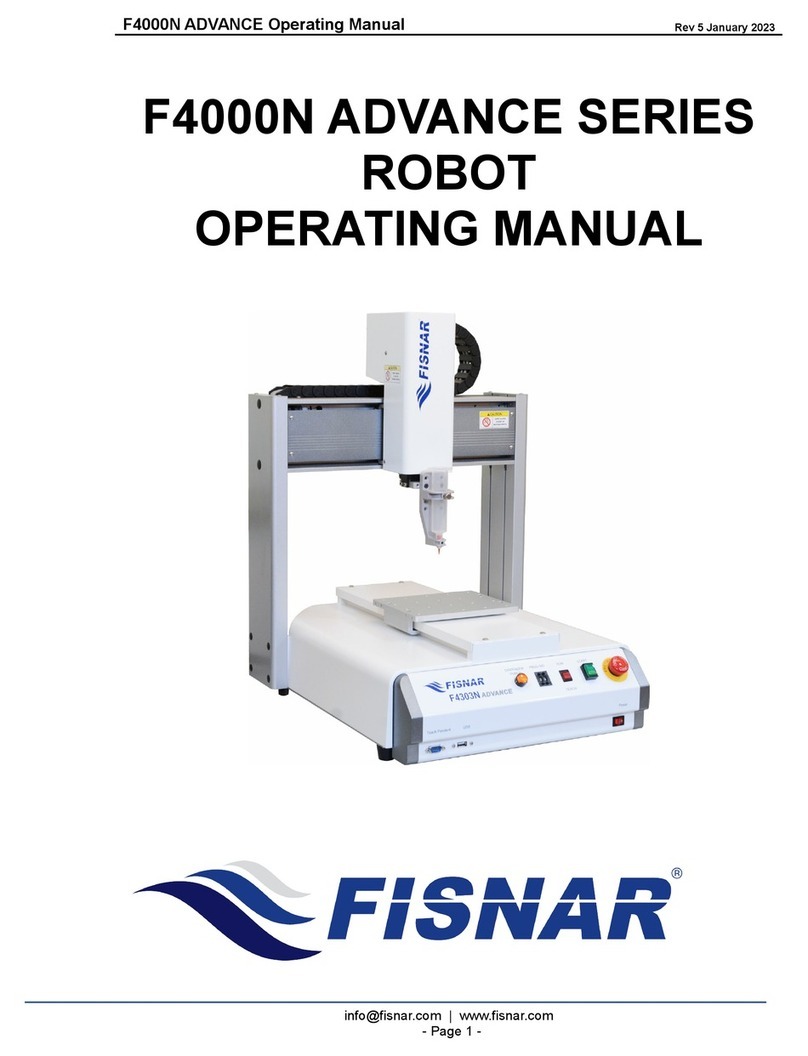
F4000N Series Operating Manual
Part # 562187N-1
Rev. D Sep 2012
F4000N
SERIES ROBOT
OPERATING MANUAL

F4000N Series Operating Manual
Section 1: Contents
Part # 562187N-1
Rev. D Sep 2012
1© 2012 Fisnar Inc.
TABLE OF CONTENTS
SECTION 1: INTRODUCTION ....................................................................................4
1. SAFETY PRECAUTIONS........................................................................................................5
2. PACKAGE CONTENTS ..........................................................................................................6
3. CONNECTOR AND SWITCH LOCATIONS ...............................................................................9
SECTION 2: SETUP....................................................................................................10
1. UNPACKING THE ROBOT .....................................................................................................11
2. SETUP .................................................................................................................................11
SECTION 3: TEACHING OVERVIEW.........................................................................12
1. TEACHING OVERVIEW ........................................................................................................13
2. USING THE TEACH PENDANT ..............................................................................................15
2.1 Key Selection .......................................................................................................................................15
2.2 Key Assignments ..................................................................................................................................16
2.3 Data Entry ...........................................................................................................................................17
2.4 Running a Program .............................................................................................................................17
3. POINT TYPE &FUNCTION SUMMARY..................................................................................18
3.1 Point Menu (F1) ..................................................................................................................................18
3.2 Menu 1 (F2).........................................................................................................................................20
3.3 Utility Menu (Within Menu1)...............................................................................................................21
3.4 Menu 2 (F3).........................................................................................................................................22
3.5 Setup Menu (F4) ..................................................................................................................................23
SECTION 4: PROGRAMMING EXAMPLE .................................................................25
1. PROGRAMMING EXAMPLE...................................................................................................26
2. GOOD PROGRAMMING PRACTICES......................................................................................29
3. EDITING A PROGRAM ..........................................................................................................30
3.1 Changing a Point’s XYZ location ........................................................................................................30
3.2 Insert / Delete an Instruction...............................................................................................................30
4. CHANGING THE PROGRAM NUMBER ...................................................................................31
5. CHANGING FROM TEACH MODE TO RUN MODE..................................................................31
SECTION 5: POINT TYPE & FUNCTION REFERENCE ............................................32
1. F1 (POINT MENU)...............................................................................................................33
1.1 Dispense Dot........................................................................................................................................33
1.2 Line Start .............................................................................................................................................33
1.3 Line Passing.........................................................................................................................................34
1.4 Circle ...................................................................................................................................................34
1.5 Arc Point..............................................................................................................................................35
1.6 Line End...............................................................................................................................................35
1.7 End Program .......................................................................................................................................35
1.8 Dispense ON / OFF .............................................................................................................................36
1.9 GOTO Address.....................................................................................................................................37
1.10 Step & Repeat X...................................................................................................................................37
1.11 Step & Repeat Y...................................................................................................................................42
1.12 Brush Area...........................................................................................................................................43
1.13 Call Subroutine....................................................................................................................................50
1.14 Call Program.......................................................................................................................................51
1.15 Set I/O..................................................................................................................................................51
1.16 Wait Point............................................................................................................................................52
1.17 Stop Point ............................................................................................................................................52
1.18 Home Point..........................................................................................................................................52

F4000N Series Operating Manual
Section 1: Contents
Part # 562187N-1
Rev. D Sep 2012
2© 2012 Fisnar Inc.
1.19 Loop Address .......................................................................................................................................52
1.20 Dummy Point.......................................................................................................................................53
1.21 Initialize...............................................................................................................................................53
1.22 Label....................................................................................................................................................53
1.23 Display Counter...................................................................................................................................53
1.24 Loop Counter.......................................................................................................................................53
1.25 Dispense Output Setup.........................................................................................................................54
2. F2 (MENU 1).......................................................................................................................55
2.1 Group Edit ...........................................................................................................................................55
2.2 Expand Step & Repeat.........................................................................................................................62
2.3 Program Name.....................................................................................................................................63
2.4 Z-axis Limit (mm) ................................................................................................................................63
2.5 Initial Output Port ...............................................................................................................................63
2.6 Debug Speed (mm/s)............................................................................................................................64
2.7 Utility Menu.........................................................................................................................................64
2.8 Jog Speed.............................................................................................................................................64
2.9 Adjust Origin .......................................................................................................................................64
2.10 Control by RS232.................................................................................................................................64
2.11 Resume.................................................................................................................................................65
3. UTILITY MENU (WITHIN MENU 1) .......................................................................................66
3.1 Program...............................................................................................................................................66
3.2 Memory................................................................................................................................................66
3.3 Teach Pendant .....................................................................................................................................67
3.4 Relocate Data ......................................................................................................................................67
3.5 Lock or Unlock Program.....................................................................................................................69
3.6 Password Setup....................................................................................................................................69
3.7 Cycle Counter......................................................................................................................................69
3.8 Key Beep..............................................................................................................................................70
3.9 Test Function .......................................................................................................................................70
4. F3 (MENU 2).......................................................................................................................72
4.1 Numerical Move...................................................................................................................................72
4.2 Save Temp Point..................................................................................................................................72
4.3 Move To Temp Point............................................................................................................................72
4.4 Undo Program.....................................................................................................................................72
4.5 Redo Program......................................................................................................................................72
4.6 Debug Program...................................................................................................................................72
4.7 Move To Home Position ......................................................................................................................73
4.8 System Information..............................................................................................................................73
4.9 Execute Point.......................................................................................................................................73
4.10 Program List........................................................................................................................................73
5. F4 (SETUP MENU)...............................................................................................................74
5.1 Line Speed............................................................................................................................................74
5.2 Line Dispense Setup.............................................................................................................................74
5.3 Point Dispense Setup ...........................................................................................................................75
5.4 Dispense End Setup .............................................................................................................................75
5.5 Z Clearance .........................................................................................................................................77
5.6 X/Y Move Speed...................................................................................................................................78
5.7 Z Move Speed.......................................................................................................................................78
5.8 Home Position Setup............................................................................................................................79
5.9 Adjust Position Setup...........................................................................................................................80
5.10 Retract Setup........................................................................................................................................82
5.11 Quickstep .............................................................................................................................................84
5.12 Auto Purge Setup.................................................................................................................................85
5.13 ESTOP Output Status...........................................................................................................................85
5.14 Acceleration.........................................................................................................................................86
5.15 Pause Status.........................................................................................................................................86
5.16 USB Up/Down Load ............................................................................................................................87
SECTION 6: SAMPLE PROGRAMS...........................................................................89
1. DOTS,LINES AND ARCS –SAMPLE PROGRAM ....................................................................90
2. BRUSH AREA –SAMPLE PROGRAM.....................................................................................92
3. STEP &REPEAT –SAMPLE PROGRAM................................................................................93
4. INPUT /OUTPUT SIGNAL PROCESSING –SAMPLE PROGRAM...............................................95

F4000N Series Operating Manual
Section 1: Contents
Part # 562187N-1
Rev. D Sep 2012
3© 2012 Fisnar Inc.
SECTION 7: ERROR MESSAGES AND SPECIFICATIONS......................................97
1. ERROR MESSAGES ..............................................................................................................98
1.1 Point Closed Error ..............................................................................................................................98
1.2 Need Line Start Point...........................................................................................................................98
1.3 Need Step & Repeat.............................................................................................................................98
1.4 Unlock Program ..................................................................................................................................98
1.5 Address Over Memory .........................................................................................................................99
1.6 Move Over Memory .............................................................................................................................99
1.7 System Error........................................................................................................................................99
2. I/O SPECIFICATIONS............................................................................................................100
2.1 Dispenser Connector:..........................................................................................................................100
2.2 Ext. Control Connector: ......................................................................................................................101
2.3 Output Signals .....................................................................................................................................102
2.4 Input Signals........................................................................................................................................103
2.5 Input / Output Schematic .....................................................................................................................104
2.6 Input / Output Power Specifications....................................................................................................104
2.7 Robot External I/O Card......................................................................................................................105
3. SYSTEM SPECIFICATIONS ....................................................................................................106
4. MACHINE DIMENSIONS.......................................................................................................107
4.1 F4300N Dimensions ............................................................................................................................107
4.2 F4400N Dimensions ............................................................................................................................108
4.3 F4500N Dimensions ............................................................................................................................109
4.4 Work Table Dimensions.......................................................................................................................110
SECTION 8: MAINTENANCE AND PERIODIC INSPECTION…………………………111
1. CHECK CYCLES AND METHODS ..........................................................................................112
1.1 General Consideration ........................................................................................................................112
1.2 Check Cycles and Points......................................................................................................................112
1.3 Check Methods.....................................................................................................................................113
2. GREASING PROCEDURE.......................................................................................................114
2.1 Grease Type and Greasing Interval.....................................................................................................114
2.2 Accessing Parts to be Greased ............................................................................................................114

F4000N Series Operating Manual
Section 1: Introduction
Part # 562187N-1
Rev. D Sep 2012
4© 2012 Fisnar Inc.
SECTION 1: Introduction

F4000N Series Operating Manual
Section 1: Introduction
Part # 562187N-1
Rev. D Sep 2012
5© 2012 Fisnar Inc.
1. Safety Precautions
1.1 Make sure the robot is connected to a properly grounded power source before
operating.
1.2 Keep away from any moving parts while the robot is running.
1.3 Loading and unloading of parts and material must only be done when the robot is at
a complete stop.
1.4 Changing of fixtures or tooling must be done with the power source disconnected.
1.5 The F4000N series robots should only be operated in an environment between 0 and
40 degrees Celsius with humidity of 20 to 95 percent and no visible condensation.
1.6 Do not store or setup the robot in an area where it is directly exposed to sunlight.
1.7 Do not operate the robot where electrical noise is present.
1.8 Only use a neutral chemical for cleaning the robot. Do not use alcohol, benzene or
thinner as it may damage the paint on the robot.
1.9 Due to the electronic nature of this equipment and the potential for a spark or
generation of heat, note that this equipment must NOT be used with any explosive
material or in an explosive type environment.

F4000N Series Operating Manual
Section 1: Introduction
Part # 562187N-1
Rev. D Sep 2012
6© 2012 Fisnar Inc.
2. Package Contents
In addition to this operating manual, the following items should be included with the robot:
Main Unit
(F4000N)
Enclosure
(CE Units Only –Not Included)
Teach Pendant
Barrel Holder
Spare Screws and Hex Key
Teach Pendant Cable
Power Cord
Dispenser Cable
RS232 Cable and Null Modem Adapter
(optional)
Start / Stop Box
(optional)
- External Control Connector
- Spare Control Connector
- Barrel and Air Line
Shorted and Non-Shorted EMG Plugs
USB Drive –Special for this Robot

F4000N Series Operating Manual
Section 1: Introduction
Part # 562187N-1
Rev. D Sep 2012
7© 2012 Fisnar Inc.
F4000N-USB Instructions
NOTICE: DO NOT LOSE THIS DRIVE
A USB flash drive (p/n: F4000N-USB) is included as part of the standard accessory kit for
the F4000N Series robot.
Saving and loading programs as well as updating the robot firmware can be done directly
with the flash drive provided.
Please note that not all commercially-available USB drives are compatible with the robot.
We do not recommend using any other USB drives other than the one provided.
Fisnar, Inc. will not be held liable for any issues arising from external hardware being
used with the robot without a written consent from Fisnar.
Caution: The instructions below are excerpts from the manual and are meant as
a quick reference guide here only. Please refer to the manual for
complete instructions.
Uploading/Downloading Programs
Instructions:
1) Turn the robot OFF. Connect the USB drive to Robot USB port and then turn the
robot ON.
2) Initialize the robot.
3) On the Setup Menu, select USB Up/Down Load.
All Data: Copies all program files.
Part Data: Allows the user to select which program files to be loaded / saved.

F4000N Series Operating Manual
Section 1: Introduction
Part # 562187N-1
Rev. D Sep 2012
8© 2012 Fisnar Inc.
Note: The robot automatically assigns the program number as its filename when saved to
the USB drive. It uses this filename to load the program to the same number on the
robot.
Updating Robot Software
Instructions:
1) On the USB drive, create an “updata” folder and copy the software files. The
software folder should include the batch (.bat), MS-DOS (.com) and executable
(.exe) files.
2) Turn the robot OFF. Insert the USB drive into the port and turn the robot ON.
3) The robot will automatically locate the “updata” folder in the drive and run the batch
file to update the software. You should see the Machine Home screen after the
update.
4) Verify the software by pressing F3 (Menu 2) System Information.
5) Turn the robot OFF and remove the USB drive.
Note: The robot will keep updating the software whenever it sees an “updata” folder,
rename the folder (and still keep it in the drive) in order to avoid this.

F4000N Series Operating Manual
Section 1: Introduction
Part # 562187N-1
Rev. D Sep 2012
9© 2012 Fisnar Inc.
3. Connector and Switch Locations
Front View
Rear View

F4000N Series Operating Manual
Section 2: Setup
Part # 562187N-1
Rev. D Sep 2012
10 © 2012 Fisnar Inc.
SECTION 2: Setup

F4000N Series Operating Manual
Section 2: Setup
Part # 562187N-1
Rev. D Sep 2012
11 © 2012 Fisnar Inc.
1. Unpacking the Robot
Always lift the robot from its base. Never lift the robot from the cross member.
Remove all accessories from the shipping package before attempting to remove the
robot.
Place the robot on a stable workbench before operating.
If possible, do not discard the packing material as these items may be needed if the
robot is shipped or moved in the future.
2. Setup
F4000N robots are available with different configurations. The setup of each machine with
its accessories will depend on the customer‟s application.
If an enclosure is NOT being used, the enclosure door switch may be bypassed by
connecting the plug labeled SHORTED (included in the robot accessories box) to
the External Control Connector. If a long beep (3-4 seconds) sounds upon start up,
ensure that the SHORTED plug is firmly in place.
2.1. When using an enclosure or light curtain connect the external start / stop box and
enclosure door switch or light curtain to the External Control Connector on the main
unit. For further information, see SECTION 7:2.2 Ext. Control Connector:
2.2. Remove the shipping bracket by removing the screws that secure it. Keep the
shipping bracket and screws in a safe place for future use.
2.3. Connect one end of the Teach Pendant cable to the Teach Pendant and the other
end to the Teach Pendant connection on the robot.
2.4. Connect the power cord to the robots power inlet. Be sure to use the correct power
cord and power source for the robot model you are using (110V or 220V).
2.5. Tie back all cables and air lines so that they will not interfere with the robot‟s motion
when the robot is operating. Be sure that the cables and air lines do not restrict the
motion of the robot‟s head and the robot‟s table and make sure that they can not
become jammed as the robot moves through the work area.

F4000N Series Operating Manual
Section 3: Teaching Overview
Part # 562187N-1
Rev. D Sep 2012
12 © 2012 Fisnar Inc.
SECTION 3: Teaching Overview

F4000N Series Operating Manual
Section 3: Teaching Overview
Part # 562187N-1
Rev. D Sep 2012
13 © 2012 Fisnar Inc.
1. Teaching Overview
A program consists of a series of instructions stored in the main memory unit. Each
instruction is stored in a numbered memory address. A memory address may record a
point location with an X, Y, and Z-axis value and point type or it may store an instruction,
which sets a parameter, such as a dispensing time or line speed.
When the program is executed, the robot will go through each memory address in
sequence and execute the instruction found there. If the memory address contains a point
location, the robot will move the X, Y, and Z axes to that location. Depending on the type
of point registered at that location, the robot may also perform other functions, such as
turning the dispenser on or off.
The most commonly used point types are Dispense Dot, Line Start, Line Passing, Arc
Point, and Line End.
To program the robot to dispense a „dot‟ of material, the dispensing tip must be jogged to
the desired XYZ location, then that location is registered as a DISPENSE DOT point type
by pressing the appropriate keys on the Teach Pendant.
To program the robot to dispense a bead of material along a linear path, the XYZ location
of the start of the line is registered as a LINE START point type. The locations where the
tip changes direction are registered as LINE PASSING points. The end of the line is
registered as a LINE END point:
Dispense Dot

F4000N Series Operating Manual
Section 3: Teaching Overview
Part # 562187N-1
Rev. D Sep 2012
14 © 2012 Fisnar Inc.
To dispense a bead of material in an arc, the XYZ location of the start of the line is
registered as a LINE START point type. The high point of the arc is registered as an ARC
POINT. The end of the arc is registered as a LINE END point:
Lines and arcs can also be combined to dispense a bead of material along a complex
path:
Once the required point locations for your program have been taught, the teach pendant is
no longer required. The unit can be switched to RUN mode and operated using the
buttons and switches on the main unit control panel.

F4000N Series Operating Manual
Section 3: Teaching Overview
Part # 562187N-1
Rev. D Sep 2012
15 © 2012 Fisnar Inc.
2. Using the Teach Pendant
The teach pendant enables the user to jog the robot and input program data.
2.1 Key Selection
There are several functions assigned to most keys on the Teach pendant. When a key is
pressed alone, the function shown in the blue colored area on the key is executed. For
example, Ins, Del, Jump, Clear and Esc are the default key functions, which are
executed when that key is pressed alone.
To access the function shown in the red colored area at the top of a key, press and
release the Shift key first (the LED on the Shift key will be flashing), then press the
desired key. For example, to select the Speed function, press and release Shift, then
press the Speed key.
When a number is required, the teach pendant will automatically switch to numeric entry
mode. The number represented by each key is shown in the lower right corner of the key.
If Shift is pressed,
released, then the
Speed key is
pressed, Speed
Setup is executed.
If this key is
pressed alone,
Jump is executed.
When entering
numbers, this key is
0.

F4000N Series Operating Manual
Section 3: Teaching Overview
Part # 562187N-1
Rev. D Sep 2012
16 © 2012 Fisnar Inc.
2.2 Key Assignments
Menu Keys
Opens the
Point Menu.
Opens Menu
1.
Opens Menu 2.
Opens the
Setup Menu.
Jog Keys
Jogs the Y-axis in
the forward
direction.
Jogs the X-axis in
the right direction.
Jogs the Z-axis DOWN.
Jogs the Y-axis in
the backward
direction.
Jogs the X-axis in
the left direction.
Jogs the Z-axis UP.
Accelerates jog speed – used with X+, X-. Y+, Y-, Z Up, Z Down
If the FAST button is pressed and held first, then one of the jog buttons is
pressed, the axis will be jogged at the maximum jog speed.
If one of the jog buttons is pressed first, then the FAST button is pressed, the jog
motion will accelerate.
If the FAST button is released, the jog motion will decelerate.
Key Assignments
Moves backward
(-1) memory
address.
Changes the
display to
memory address
number 1.
Inserts a memory address
before the current address.
Moves forward
(+1) memory
address.
Changes the
display to the last
memory address
used in the
program.
Deletes the current memory
address.
Moves the tip to the
point location
currently in the
display.
Jumps to a
specified memory
address
Clears / erases the numeric
value currently shown in the
display.
Adjusts the tips
position after a
barrel change
To run the
program
Homes the robot. Initializes
all axes and moves the
head to the position (0, 0,
0).
(Enter)–used to
confirm data
entries.
Opens the Point
registration menu.
If pressed once, clears the current numeric value.
If pressed twice, cancels the current function.
If a program is running, cancels the running program.
Changes from Point List display mode to Single Point
display when teaching point data.

F4000N Series Operating Manual
Section 3: Teaching Overview
Part # 562187N-1
Rev. D Sep 2012
17 © 2012 Fisnar Inc.
Key Functions
→
Registers a DISPENSE
DOT point.
→
Registers a LINE START
point.
→
Registers a LINE
PASSING point.
→
Registers a LINE END
point.
→
Registers an ARC POINT.
→
Registers a Line Speed
command.
→
Registers a Point
Dispense Setup
command.
→
Registers a Line Dispense
Setup command.
→
Registers the End
Program command.
→
Redo Last Entry
→
Undo Last Entry
→
Registers a Z Clearance
command.
2.3 Data Entry
When a number is required, the teach pendant will automatically switch to numeric entry
mode. The number represented by each key is shown in the lower right corner of the key.
2.4 Running a Program
Press the key to run the program.

F4000N Series Operating Manual
Section 3: Teaching Overview
Part # 562187N-1
Rev. D Sep 2012
18 © 2012 Fisnar Inc.
3. Point Type & Function Summary
3.1 Point Menu (F1)
Below is a list of Point Types, which are found under the F1 key (Point menu):
Function
Description
Dispense Dot
Registers the current XYZ location as a Dispense point for dot
dispensing.
Line Start
Registers the current XYZ location as a Line Start point for line
dispensing.
Line Passing
Registers the current XYZ location as a Line Passing point. This is a
location on the line where the tip changes direction, such as at the
corner on a rectangle.
Circle
Registers a circle with the circle center at the current XYZ location. The
display will prompt the user for the circle diameter.
Arc Point
Registers the current XYZ location as an Arc point. Arc points are used
to dispense material in an arc or circle.
Line End
Registers the current XYZ location as a Line End point.
End Program
Registers the current memory address as the end of the program.
Dispense On /
Off
Registers an instruction which turns the dispenser on or off at the
current XYZ location.
GOTO
Address
Causes the program to jump to the specified memory address.
Step & Repeat
Registers an instruction that will re-run a selected group of memory
addresses, stepping by a user-defined distance in the X or Y-axis after
each copy. The matrix of parts is defined by specifying the number of
rows, the number of columns, the X offset and the Y offset.
Step & Repeat X indicates that the robot will give priority to the X-axis,
running the parts along the X-axis first.
Step & Repeat Y indicates that the robot will give priority to the Y-axis,
running the parts along the Y-axis first.
Brush Area
Causes the tip to „paint‟ the defined area. The painted area can be in
the form of a rectangle or a circle / spiral.
Call
Subroutine
Causes the machine to jump to a specified memory address and
execute the instructions found there. When the end program instruction
is reached, program execution will continue at address just after the call
Subroutine instruction.

F4000N Series Operating Manual
Section 3: Teaching Overview
Part # 562187N-1
Rev. D Sep 2012
19 © 2012 Fisnar Inc.
Function
Description
Call Program
Jumps to the specified program number from within the current
program.
Set I/O
Registers an instruction, which either sets the value of an output signal
or checks the status of an input signal.
Wait Point
After executing the current point (Line start, passing, etc) the robot will
wait a specified amount of time before moving to the next command.
Stop Point
After executing the current point (Line start, passing, etc), the robot will
wait until the start button is pressed before moving to the next
command.
Home Point
Registers an instruction to „home‟ all axes, sending them to the home
position. See the Setup Menu for instructions on changing the location
of the home position.
Loop Address
Causes the program to execute a group of memory addresses a user-
specified number of times.
Dummy Point
Registers the current XYZ location as a Dummy point. The tip will
simply pass through this point. Useful for avoiding obstacles on the
work piece.
Initialize
Registers an Initialize point. Causes the robot to perform a mechanical
initialization.
Label
Registers a label that can be used as a reference when used with the
GOTO address, Loop address, Set I/O, Step & repeat X, Step & repeat
Y and Call Subroutine commands.
Display
Counter
Shows a counter at the bottom of the teach pendant screen while a
program is running.
Loop Counter
The Loop Counter either clears or keeps the current tally of the counter
when an I/O signal is received. The tally is cumulatively added to the
current count on the display counter.
Dispense
Output Setup
Defines the dispense output port number for line dispense setup.
Table of contents
Other FISNAR Robotics manuals
