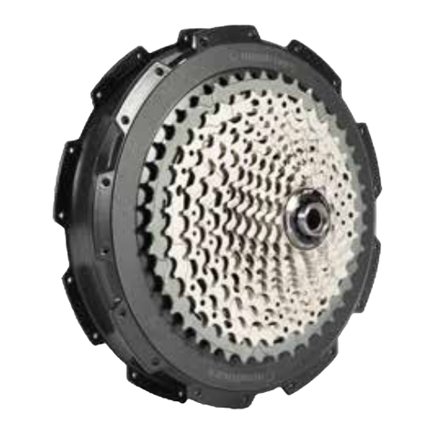
Neodrives Z20 RS User manual

Alber GmbH
Vor dem Weißen Stein 14
72461 Albstadt
Phone 07432 2006-0
Fax 07432 2006-299
info@alber.de
www.neodrives.de
94.0006.6.02.01 Version 04/2020 © Alber GmbH, Albstadt. Subject to technical change.
Z20 RS |USER MANUAL
DER HECKMOTOR

2 3
CONTENTS
CONTENTS
CONTENTS
01 INTRODUCTION......................................................................................... 5
01.1 Important notes – please observe!......................................................................... 6
01.2 Permissible operating conditions/locations for use..............................................7
02 SCOPE OF DELIVERY
NEODRIVES COMPONENTS ........................................................ 9
02.1 Technical data ..........................................................................................................10
02.1.1 Drive unit.....................................................................................................................11
02.1.2 LCD and control unit ................................................................................................12
02.1.3 Baery V8 Z20 RS......................................................................................................13
02.1.4 Total system ...............................................................................................................14
02.1.5 Factors influencing the remaining range..............................................................15
02.2 Starting the system ..................................................................................................16
02.3 neoRemote Z20RS....................................................................................................18
02.4 neoNode Z20 RS.......................................................................................................19
03 neoMMI.............................................................................................................21
03.1 Sokeys......................................................................................................................21
03.2 Display types............................................................................................................. 22
04 BATTERY ............................................................................................................31
04.1 Baery LED display/baery buon....................................................................... 32
04.2 Switching on the baery ........................................................................................ 33
04.3 Charging and storing the baery.......................................................................... 34
04.4 Removing and inserting the baery..................................................................... 36
05 MOTOR .............................................................................................................. 37
05.1 Installation and removal of the rear wheel .......................................................... 38
05.2 Recuperation .............................................................................................................41
05.3 Thermal management ............................................................................................ 42
06 NOTES AND TROUBLESHOOTING......................................44
06.1 Maximum axle load................................................................................................. 45
06.2 Cleaning .................................................................................................................... 45
06.3 Transport ...................................................................................................................46
06.4 Safety precautions................................................................................................... 47
06.5 Fault symptoms and possible measures ..............................................................48

4 5
01 |INTRODUCTION
01 |INTRODUCTION
01 |INTRODUCTION
DEAR CUSTOMER,
This user manual will give you a comprehensive overview of
the use of the neodrives hub motor system Z20 RS.
When developing the system, we focused on maximum riding
performance – no other system should give a smoother, more
agile ride than the neodrives hub motor.
So just pedal away and enjoy your ride to the max!
We hope your ride with the neodrives Z20 RS hub motor is a
real pleasure!

6 7
01 |INTRODUCTION
01 |INTRODUCTION
In addition to this user manual, further documents are enclo-
sed with your S-Pedelec. Please observe the instructions and
notes contained therein. There is currently a legal obligation to
wear a helmet when using an S-Pedelec.
INTENDED USE OF NEODRIVES
COMPONENTS
The S-Pedelec with neodrives components, supplied by spe-
cialist dealers, is designed as a trekking or city bike for normal
person transport on public roads.
Seings and repairs to the S-Pedelec and to individual com-
ponents are considered intended use only if they are explained
and permied in this user manual, in the user manual of the
S-Pedelec manufacturer, in the instructions of the component
manufacturers or in other documents enclosed with the pur-
chase of the S-Pedelec.
The manufacturer accepts no liability for damage caused neg-
ligently by misuse, improper maintenance, improper repairs or
improper use. It is the responsibility of the rider to check the
S-Pedelec as prescribed, to have any necessary work done on
it and to use it responsibly. This user manual describes exclu-
sively the use of the neodrives components aached to your
S-Pedelec and is state-of-the-art at the time of printing. The
manufacturer reserves the right to make changes resulting
from the further development of mechanics, soware or legal
requirements.
01.1 | IMPORTANT NOTES
PLEASE OBSERVE!
The manufacturer regards the following cases as misuse of the
neodrives components aached to your S-Pedelec:
• Use of the drive system contrary to the instructions and
recommendations of this user manual
• Exceeding the technical performance limits defined in this
user manual
• Technical modifications to the neodrives components
• Changes to the soware of the neodrives components
• Unauthorised mounting or unauthorised use of neodrives
components on bicycles or on any S-Pedelec other than the
one supplied to you
The manufacturer declines any liability for damage resulting
from misuse of the components. Before starting the journey,
familiarise yourself with the safety and hazard notices in the
individual chapters of these operating instructions and all
other enclosed documents.
01.2 | PERMISSIBLE OPERATING
CONDITIONS / LOCATIONS FOR USE
The neodrives components can be operated at temperatures
of between -10°C and 60°C → see page14. In addition,
observe the information on permissible operating conditions
in the operating instructions of the S-Pedelec manufacturer.
Their restrictions of the permissible operating conditions (e.g.
maximum climbing capability, maximum permissible obstacle
height, maximum user weight) must also be observed when
using the S-Pedelec! Observe the safety and hazard notices in
the individual chapters of these operating instructions.

8 9
02 |SCOPE OF DELIVERY
02 |SCOPE OF DELIVERY
NEODRIVES COMPONENTS
OF DELIVERY
• neodrives hub motor Z20 RS
• neoNode Z20 RS (installed in the S-Pedelec)
• neoTwistlock Z20 RS and neoRemote Z20 RS (control element)
• neoMMI Z20 RS (LCD)
• Cable harness Z20 RS
• User manual
The neodrives Z20 RS drive system has only a few individual
components.
NOTE: Example, the baery and its positioning may vary
depending on the bike.
IMPORTANT:
The components of the new Z20 RS S-Pedelec drive system
are not compatible with the components of the Z20 (E-Bike 25
ph) or its predecessor versions Z10/Z15, i.e. the system compo-
nents cannot be interchanged.
02 |SCOPE OF DELIVERY
NEODRIVES neoNODE Z20 RS
The mounting of the neoNode Z20 RS depends on the
bicycle model. It is integrated in the frame.
TORQUE RECEIVER CAB LE
HARNESS
neoTWISTLOCK Z20 RS
with neoRemote Z20 RS
neoMMI Z20 RS
NEODRIVES
BATTERY V8 RS
NEODRIVES
Z20 RS HUB MOTOR

10 11
02 |SCOPE OF DELIVERY
02 |SCOPE OF DELIVERY
NEODRIVES HUB MOTOR
01. Hub motor Z20 RS with stub axle
02. neoMMI Z20 RS
03. neoTwistlock Z20 RS – with neoRemote Z20 RS
04. Torque receiver
05. Z20 RS Cable harness, available in different lengths
06. Installation kit for neoTwistlock Z20 RS
07. Baery V8 Z20 RS
Baery charger Z20 RS
neoNode Z20 RS
DRIVE UNIT
Speed 45km/h
Power rating peak 1200 Wa
Operating voltage 48 Volt
Nominal torque 12Nm
Peak torque 40Nm
Efficiency > 85 % (incl. electronics)
Power electronics control
system Integrated in the wheel hub
Cassee hub
Conventional cassee, up to
11 speeds
(Shimano MTB) or belt disk
Brake disc From a diameter of 180mm
Weight approx. 4 kg
GENERAL COMPONENTS
02.1 | TECHNICAL DATA
02.1.1 |DRIVE UNIT
01. Hub motor Z20 RS
07. Baery V8 Z20 RS
02. neoMMI Z20 RS 03. neoTwistlock Z20 RS
with neoRemote Z20 RS
06.Installation kit for
neoTwistlock Z20 RS
04.Torque receiver
(different designs)
05. Z20 RS cable harness
(different designs)

12 13
neoREMOTE Z20 RS (CONTROL ELEMENT)
Buons: Power, Set, Support-Level "+" and "–", 22.2 mm
internal diameter, permanent cable
neoTWISTLOCK Z20 RS (MOUNTING PLATE)
Rocker arm mounting, angle adjustable in 15° increments
Weight (incl. cable and neoRemote Z20 RS) 55 g
02.1 | TECHNICAL DATA
02.1.2 |LCD AND CONTROL UNIT
(neoREMOTE Z20 RS AND neoTWISTLOCK Z20 RS)
02.1.3 |BATTERY
LCD neoMMI Z20 RS
LCD control Colour
Touchscreen Rainproof and glove com-
patible
Sokeys 3 Sokeys:
Back, Home, Menu
LCD size,
resolution 2 inch, 240 x 320 Pixel
Dimensions without neo
Twistlock (W x L x H) 48mm x 64mm x 19mm
Internal memory 4GB
Connectivity Bluetooth
Interfaces USB-C
Mechanical/electrical con-
tacting
Twistlock, corrosion-protec-
ted contacts, spring-moun-
ted
LCD type TFT
LCD screen Reinforced, non-reflecting
Dragontrail glass
Waterproof IP67
LCD 20c weight
(removed) 54g
V8
Type Integrated baery
Baery type Lithium-ion
Cell INR18650 BMZ 35E
Nominal capacity 13.8Ah
Voltage 48V
Energy content 651Wh
Range*
Assistance level 3:
up to approx. 60 km
Assistance level 5:
up to approx. 40 km
Weight approx. 4.2 kg
Charging In the bicycle or
removed from the bicycle
End-of-charge voltage 54.6V
Baery charger 4A
Protection class IP X7
Operating ambient
temperature
Discharging: -10 °C to +60 °C
Charging: 0 °C to +50 °C
The neodrives Z20 RS hub motor is available in combination
with the baery V8 Z20 RS, please observe the separate user
manual for the baery.
* The range will vary depending on the baery, the terrain as
well as the prevailing ride conditions. With optimum riding
conditions (for example, level terrain, a fully charged baery,
ambient temperature of 20 °C, steady ride), a pedalling per-
formance of 80 Wa, a speed of 39 km/h and a wheel circum-
ference of 2280 mm (28 inches).
02 |SCOPE OF DELIVERY
02 |SCOPE OF DELIVERY

14 15
02.1.4 |TOTAL SYSTEM 02.1.5 |FACTORS INFLUENCING THE REMAINING RANGE
We reserve the right to make changes in technology and design
due to on-going further developments.
NOTES
Operating temperature
-10 °C to +60° C
Charging (incl. recuperation):
0 °C to +50 C°
Protection class IPx4
The neodrives motor was designed for high performance and
achieves an efficiency factor of approx. 87 %. As this is a direct
drive mechanism (no gears like on mid-drive motors for
example), the losses are minimal.
The range the rider is able to achieve depends on numerous
factors. These are the main ones:
• Topography: Travelling on hilly terrain noticeably affects the
baery more than travelling on flat terrain.
• Weather: On cold days the baery range can be 30-40% less
than on warm days. Head wind also affects power consump-
tion.
• Frequent acceleration/travelling at low speeds: Large
amounts of power are needed to accelerate. Comparable
with the high instantaneous fuel consumption occurring on
a car when starting off.
• System weight: This factor is oen underestimated. The
weight of the rider and their belongings contribute conside-
rably to the overall mass of the bike (different to a car).
• Rider's effort: the more effort the rider puts in, the longer
the achievable range. It oen helps to switch down 1-2gears
to increase the input force or the cadence.
• Tyre pressure: If the tyre pressure is too low, the friction bet-
ween the tyre and the ground surface increases, potentially
causing several percentage points to be lost.
• Air resistance: At high speeds (from 35 km/h), the air resis-
tance increases disproportionally. Riding at medium speeds
increases the range.
• Recuperation: Utilise the recuperation modes, e.g. when
riding downhill, to increase the baery range.
• Cold conditions: If you store your baery in warmer
rooms during winter, it will provide more power.
ONE MOTOR
WITH HIGH
EFFICIENCY
02 |SCOPE OF DELIVERY
02 |SCOPE OF DELIVERY

16 17
01. 03.
02.
02 |SCOPE OF DELIVERY
02 |SCOPE OF DELIVERY
LCD FIXING BRACK ON THE neoTWISTLOCK Z20 RS
If required, you can aach the LCD to the neoTwistlock Z20 RS.
Use a 1.5mm Allen key to do this.
SWITCHING ON
Press and hold the on/off buon for one second. The neodri-
ves logo will appear in one second and the light will switch on
automatically. Wait until the trip screen appears. This can take
up to 5seconds.
It is not necessary to press the baery buon beforehand.
CONNECTING THE LCD WITH neoT
WISTLOCK Z20 RS
01. neoTwistlock Z20 RS is mounted
02. Set the LCD at a 90° angle,
turn clockwise to open it
03. Done
REMOVAL
Turn the LCD on the mounting plate clockwise through ap-
prox. 90°. This detaches the electrical connections and the
LCD can be removed. The system (LCD + S-Pedelec) should be
switched off prior to removal. However, there will be no dama-
ge if you mount or dismount the LCD while the S-Pedelec is
switched on.
NOTES:
To protect your S-Pedelec from unwanted use by third parties
or the, the LCD should always be removed from the rocker
arm when not in use.
However, removing the LCD is no substitute for safeguarding
your S-Pedelec against the, e.g. with a suitable bicycle lock.
Approx. 10seconds aer removal, the system turns off. The
light, if switched on, also goes off aer approx. 10seconds. Af-
ter removing the LCD, wait approx. 30seconds before placing
it back on. Otherwise, a successful system initialisation
cannot be guaranteed.
02.2 | STARTING THE SYSTEM
The USB charging port is
located in the lower part.
System On/Off
SWITCHING OFF
Press and hold the on/off buon for one second. The neodri-
ves logo will appear in one second and the light will switch off
automatically.

18 19
The light On/Off function is deac-
tivated on the Z20 RS due to the
regulations on the S-Pedelec. A
separate switch, installed on the
rocker arm, must be used to acti-
vate the main beam.
02 |SCOPE OF DELIVERY
02 |SCOPE OF DELIVERY
MAIN TASK
Communication interface between baery/motor and
LCD. This is integrated in the down tube or in the vicinity of the
boom bracket or control tube. It is a small and robust plug
for quick disassembly.
NOTE ON PLUG MOUNTING PLATE
If you have to open the two plugs of the cable leading from
the neoTwistlock Z20 RS mounting plate to the frame, it is es-
sential to observe the following instructions when assembling.
NOTES: The male plug of the mounting plate (see illustra-
tion above le) and the female plug on the connecting cable
(see illustration above right) must be correctly aligned when
joining. Both plugs are marked. Align the markings (see illus-
tration in the middle) and carefully push the plugs together
(see illustration below). If the plugs are not aligned correctly,
they may be damaged during assembly.
When unplugging and plugging in, grip only the plugs, not
the cable. Do not kink the cable when assembling the plugs to
avoid damaging it!
CONNECTING A HEADLIGHT
The system provides a current output for e-bike lights. Only
approved lights may be connected to the neodrives system.
In addition, specific standards must be adhered to with the S-
Pedelec. Only headlights that have been tested for the specific
S-Pedelec by the bicycle manufacturer and approved by TÜV
may be used.
The neo-Remote on the le-hand side of your S-Pedelec's
rocker arm allows you to make seings to your S-Pedelec
at any time, such as the degree of pedal assistance, without
taking your hands off the rocker arm. The same applies to the
horn function and the main beam and dipped beam function,
which are activated or deactivated via the additional buons
on the rocker arm.
02.3 | neoREMOTE Z20 RS 02.3 | neoNODE Z20 RS
LIGHT ON/OFFSYSTEM ON/OFF
"SET" BUTTON:
• Scroll through the LCD menu (neoMMI
Z20 RS)
IMPORTANT
Align markings prior to
pressing together!
"" BU T TO N
• Decrease the assistance level
• Activate recuperation
"+" BUTTON
• Increase the assistance le-
vel by pressing the buon
• Activate the walk assist
(4km/h) by pressing and
holding the buon for
3seconds
Cable to LCD
(neoTwistlock Z20 RS)
Cable to baery
Plug connection
neoTWISTLOCK Z20 RS

20 21
1. 2. 3.
03 |neoMMI
SOFTKEYS
1. Back
a) Within the menus, this takes you
back to the previous selection, or alter-
natively press the "Set" buon on the
neoRemote Z20 RS
b) Toggles between the 3 display mo-
des
2. Home Takes you to the main display
3. Menu Opens and closes menus
03 |neoMMI
03 |neoMMI
The neoMMI Z20 RS is equipped with a 2-inch colour TFT LCD
with 3 sokeys (keys on touch LCD). This LCD can be operated
with the rocker arm unit neoRemote Z20 RS
(→ siehe Seite 18) as well as with the touchscreen of the LCD
and the 3 sokeys.
There are 3 sokeys at the boom of the TFT LCD. The func-
tions of the buons are, from le to right, "Back", "Home"
and "Menu". The triangular "Back" buon takes you back to
the previous selection within the menus. The round "Home"
buon takes you to the main display. The main display is the
starting point of the LCD, which has a total of 3 display modes.
The square "Menu" buon opens and closes menus. You can
make various seings in the menus. For example, you can
specify whether the speed is displayed in kilometres per hour
(km/h) or miles per hour (mph).
03.1 | SOFTKEYS

22 23
03 |neoMMI
03 |neoMMI
MAIN DISPLAY SCREEN
4. Headlight
5. Time
6. Speed
7. Walk assist
8. Assistance
9. Range
TRIP DISPLAY SCREEN
10. Distance
11. Trip time
POWER DISPLAY SCREEN
12. Ratio
13. Kilocalories
14. Cadence
The LCD has 3 display modes: the main display, the power
display and the trip display. Use the "Set" buon on the neo-
Remote Z20 RS rocker arm control → see chapter 2, to toggle
between these displays. Press the "Home" buon to return
directly to the main display at any time.
03.2 | DISPLAY TYPES
MENU
To access the menu, please press the "Menu" buon briefly.
MENU ITEM SELECTION
Trip > reset trip
Inspection
Seings Touchscreen
Baery
Units
Language/
Time/Date
Inactive
Active
Symbol
Percentage
Range
Metric
Imperial
Set time
Set date
Select the desired menu item by tapping the display. This will
take you to the sublevel you require.
To exit the menu, please press the "Menu" or "Home" but-
ton. This will take you to the main display.
HEADLIGHT
To comply with the legal requirements concerning the S-
Pedelec, the headlight must be switched on at all times.
9. 8.
4. 5.
6.
11.10. 13.
14.
12.
7.
Main display Trip display Power display

24 25
03 |neoMMI
03 |neoMMI
TRIP MENU ITEM
01. Tap the Trip menu item in the main menu. This will take
you to sublevel 1, where the following menu items are
displayed:
Trip Distance
Time
kcal
02. To reset the three values shown for distance, time and
kcal to "0", tap "Reset".
03. To go back to the main menu, tap "Trip" at the top or
press the "Menu" or "Back" buon.
04. If you want to go straight back to the main display, press
the "Home" buon.
INSPECTION MENU
Tapping the "Inspection" menu item in the top level takes
you to this menu item. The following items are displayed: the
frame number, when the next inspection is due, how oen the
baery has been charged, and the total distance the S-Pe-
delec motor has covered so far. The odometer information
cannot be reset to "0". The soware versions of the individual
components and their IDs are also displayed here). You can
return to the top level of the menu by tapping either "Inspec-
tion" at the top or the "Back" buon in the boom le corner.
Or you can leave the menus completely by tapping the round
"Home" buon in the middle at the boom. This will take you
to the main display →siehe
Seite 22.
SETTINGS MENU ITEM
Tap the "Seings" menu item in the main menu. This will
take you to sublevel 1 where the following menu items are
displayed:
Seings Touchscreen
Baery
Units
Language
Time & date
Update
A soware update temporarily stored on the
neoMMI Z20 RS can be installed by tapping "Update". This
will be uploaded to the S-Pedelec once the display is ope-
ned.
01. Tap the "Inspection" menu item in the main menu. This
will take you to sublevel 1, where the following menu
items are displayed:
Inspection Frame ID
Inspection
Use
Charge cycles
Odometer (this display cannot be reset
to "0")
Soware versions: This menu item
shows you the firmware status of the
components
To go back to the main menu, tap "Inspection" at the top or
press the "Menu" or "Back" buon.
02. If you want to go straight back to the main display, press
the "Home" buon.
You can see the firmware status of your components at a
glance.

26 27
03 |neoMMI
03 |neoMMI
TOUCHSCREEN MENU
In this menu item, you can set whether the touchscreen should
be active or inactive while riding. This can help prevent acci-
dental operation during the ride.
01. Tap "Touchscreen" in sublevel 1. This will take you to sub-
level 2, where the following menu items are displayed:
Touchscreen Inactive
Always active
02. Select the desired menu item.
03. To go back to sublevel 1, tap "Touchscreen" at the top or
press the "Back" buon.
04. If you want to go straight back to the main display, press
the "Home" buon.
BATTERY MENU ITEM
In this menu item, you can set whether the baery's state of
charge should be shown as a symbol or as a percentage and
whether the range should be displayed. The range also varies
in the menu depending on the assistance level selected.
Example: In level 5, the range is lower than in level 1
→ see page30.
Note: The distance shown in the LCD may
vary from the actual range.
01. Tap the "Baery" item in sublevel 1. This will take you to
sublevel 2, where the following menu items are displayed:
Baery Symbol
Percentage
Range
02. Select the desired menu item. A tick appears next to your
selection.
03. To go back to sublevel 1, tap "Baery" at the top or press
the "Back" buon.
04. If you want to go straight back to the main display, press
the "Menu" buon.
If the LCD shows an update from a retailer and this has not
been activated, you can activate it yourself via this menu item.
Depending on its size, an update can take up to 15 minutes to
load. Do not turn the LCD from the neoTwistlock Z20 RS, do
not switch it off via the neoRemote Z20 RS or the baery and
do not remove the baery.
01. You can select and tap one of the 5 menus displayed. This
will take you to the next sublevel.
02. To go back to the main menu, tap "Seings" at the top or
press the "Menu" or "Back" buon.
03. If you want to go straight back to the main display, press
the "Home" buon.
SAFETY PRECAUTIONS
If you use the „Always active“ seing to try and change a
seing while riding, this may not only lead to operating
errors, it can also distract you from your ride. This can
have dangerous consequences – your safety comes first!

28 29
03 |neoMMI
03 |neoMMI
UNITS MENU ITEM
In this menu, you can set whether you prefer metric units (kilo-
metres per hour (km/h) and a 24-hour clock) or imperial units
(miles per hour (mph) and a 12-hour clock) to be used in the
LCD.
01. Tap the "Units" item in sublevel 1. This will take you to
sublevel 2, where the following menu items are displayed:
Units Metric (kilometres per hour [km/h] and
24-hour clock)
Imperial (miles per hour [mph] and 12-
hour clock)
02. Select the desired menu item. A tick appears next to your
selection.
03. To go back to sublevel 1, tap "Units" at the top or press
the "Back" buon.
04. If you want to go straight back to the main display, press
the "Home" buon.
LANGUAGE MENU ITEM
In this menu item, you can set the language for the LCD. Six
languages were available at the time of writing these instructions:
English, German, French, Spanish, Italian and Dutch.
01. Tap "Language" in sublevel 1. This will take you to sublevel 2.
02. Select the desired menu item. A tick appears next to your
selection.
03. To go back to sublevel 1, tap "Language" at the top or press
the "Back" buon.
04. If you want to go straight back to the main display, press the
"Home" buon.
TIME & DATE MENU ITEM
In this menu, you can set the time and date shown in the
display.
01. Tap "Time & date" in sublevel 1. This will take you to sub-
level 2.
Time & date Time
Date
Hours
Minutes
Month
Year
02. Tap "Time" or "Date". Sublevel 3 will appear.
03. Tap to determine which of the two fields is active. The
active field has a white background with a light green
border at the boom, whereas inactive fields are light
grey. The "Time" menu gives the options of hours and
minutes, whilst the "Date" menu can be used to set the
day, month and year.
04. You can select the required values using the "+" and "-"
symbols at the boom of the LCD.
05. To go back to sublevel 2, tap "Date" at the top or press
the "Back" buon.
06. If you want to go straight back to the main display, press
the "Home" buon.

30 31
DISPLAY ASSISTANCE POWER CONSUMPTION
Assistance level 5 Assistance works
at very high power Very high
Assistance level 4 Assistance works at high power High
Assistance level 3 Assistance works at medium
power Medium
Assistance level 2 Assistance works at low power Low
Assistance level 1 Assistance works at very low
power Very low
0 (off) No assistance –
Recuperation level 1 No assistance Energy recovery
Recuperation level 2 No assistance Energy recovery
03 |neoMMI
04 |BATTERY
WALK ASSIST
When the walk assist is activated, the symbol appears in the
LCD. To activate the walk assist, start moving the bike and hold
the "+" buon on the neoRemote Z20 RS for threeseconds.
Keep the "+" buon pressed for as long as you wish to be
assisted by the motor.
ASSISTANCE MODE AND
RECUPERATION
01. Briefly press the "+/-" buon to select the level of assis-
tance you want or the level of recuperation you want to
activate.
Activation of recuperation
Press the "-" buon until the digits 1 and 2 appear in the
LCD with an energy symbol.
Recuperation level 1: The motor recovers energy. 50%
of the permissible recuperation power is generated.
Recuperation level 2: The motor recovers more
energy. 100% of the permissible recuperation power is
generated.
02. The motor will assist you according to the selected
assistance level as long as you are pedalling. As soon as
you stop pedalling or a speed of 45km/h is reached, the
motor will stop assisting you.
Walk assist symbol

32 33
04 |BATTERY
04 |BATTERY
04 |BATTERY
04.2 | SWITCHING ON
THE BATTERY
SETTING THE BATTERY TO "DEEP SLEEP" MODE
Keep the baery buon pressed for more than 5seconds:
The LEDs shut down one aer the other 5-4-3-2-1-0. When the
last LED has extinguished, keep the baery buon pressed for
another 2-3seconds. Within the next 60seconds, the baery
goes into "Deep sleep" mode.
INFORMATION: The baery is automatically set to "Deep
sleep" mode if not used (LCD switched off, baery buon
not pressed). In this state, the standby power consumption is
reduced to a minimum, to allow prolonged storage periods
without a great loss of capacity, for example.
WAKING THE BATTERY FROM "DEEP SLEEP"
Aer switching off the S-Pedelec and removing the charging
plug, the baery goes into "Deep sleep" mode to reduce the
standby power to a minimum. Press the baery buon briefly
to wake the baery up again. All 5 LEDs will light up, followed
by a brief pause aer which all LEDs will flash briefly three
times. The baery is now operational again.
Only use the baery charger provided to charge the baery.
Using an unsuitable baery charger may lead to malfunctions
and reduce the baery's service life. There is also a risk that it
may catch fire or explode.
Connect the plug on the baery charger to the mains first
before connecting the baery.
04.1 | BATTERY LED DISPLAY/
BATTERY BUTTON
The position of the baery and therefore the visibility of the
baery buon depends on the model. It can be located on the
top or boom side of the down tube. You can use the baery
buon on the top of the baery to call up the following infor-
mation or carry out the following actions:
01. Switching on the baery
02. Check the baery's state of charge
03. Seing the baery to "Deep sleep" mode
04. Waking the baery from "Deep sleep"
To ensure the display functions correctly, it may be necessary
to disconnect the baery from the system beforehand (unplug
the baery or remove it from its frame).
The baery UR V8 RS need not be wakened by pressing the
baery buon. Pressing the ON/Off buon on the neoRemo-
te Z20 RS is sufficient (siehe Seite 18). The system powers
up aer a few seconds (5 seconds), the light switches on and
the start screen appears.
CHECKING THE CURRENT STATE OF CHARGE
Press the baery buon briefly: the baery's state of charge
will be displayed
(State of Charge)
• 5 LEDs lit: baery has 80-100% charge.
• 4 LEDs lit: baery has 60-80% charge.
• 3 LEDs lit: baery has 40-60% charge.
• 2 LEDs lit: baery has 20-40% charge.
• 1 LED lit: baery has 0-20% charge.
• 1 flashing LED: baery is flat.

34 35
04 |BATTERY
04 |BATTERY
04.3 | CHARGING AND STORING
THE BATTERY
The baery can remain in the S-Pedelec while it is being
charged. Alternatively, you can remove the baery and charge
it outside the S-Pedelec.
Integrated baery UR-V8
CHARGING THE BATTERY
01. Connect the power cable to the baery charger and plug
into a socket.
02. Connect the charging plug to the charger socket on the
baery.
03. Turn the tumble switch on the baery charger to "On".
04. Aer approx. 5-10seconds, the green LED on the baery
charger flashes fast and steadily. If the LCD is connected
to theS-Pedelec, it will turn on for a fewseconds before
automatically turning off again.
05. Aer approx. 5 seconds, the LEDs on the baery light up
according to the following paern:
• All 5 LEDs flash in turn:
baery is charging, the state of charge is between 0
and 20 %.
• 1 LED is permanently lit, LED 2–5 flash in turn: baery
is charging, the state of charge is between 20 and 40 %.
• 2 LEDs are permanently lit, LED 3–5 flash in turn:
baery is charging, the state of charge is between 40 and
60 %.
• 3 LEDs are permanently lit, LED 4–5 flash in turn:
baery is charging, the state of charge is between 60 and
80 %.
• 4 LEDs are permanently lit, LED 5 is flashing:
baery is charging, the state of charge is
between 80 and 100 %.
BATTERY CHARGER DISPLAY
• Green LED flashes approx. once per second: baery char-
ging
• Green LED permanently lit: baery fully charged, charging
process complete
• Green LED flashes briefly every 2seconds: no baery con-
nected, baery not charging
• Red LED flashes: charging fault. In case of a charging fault,
please check for kinks in the cables and ensure that the
plug is clean and fied correctly. If the baery charger has
a magnetic plug: check the magnetic plug on the baery
charger and the magnetic socket on the baery for dirt from
time to time and in case of problems during charging. Metal
shavings and small parts such as washers can quickly gather
there due to the magnet.
• Charging time: a complete charge (0 % – 100 %) lasts about
4 hours. The baery charger produces a charging current of
4 A on average. This means that over a complete charging
cycle (completely flat baery to completely charged baery)
it charges with 4 A on average.
STORING THE BATTERY
• When removing the baery, make sure it is stored in a dry
place protected from foreign particles (e.g. metal shavings).
• The state of charge should be 50-80%.
• When the baery is in storage, check its state of charge eve-
ry 3 months and charge to 80% when necessary.
• Do not expose the baery to any moisture (water, rainwater,
snow, etc.) during storage!
• Store the baery in a cool, dry place where it is protected
from damage and tampering.
• To ensure optimum baery service life, it should be stored at
a temperature of 18 to 23°C and a humidity of 0 to 80%
→ siehe Seite 13.
06. When the baery is fully charged, the baery charger
switches off. The green LED on the baery charger lights
up continuously and the LEDS on the baery extinguish.
07. The baery is automatically set to "Deep sleep" mode
once the charging plug is disconnected. To "wake up" the
baery, press the baery buon once.

36 37
05 |MOTOR
04 |BATTERY
04.4 | REMOVING AND INSERTING
THE BATTERY
To release the baery, turn the key anticlockwise as far as it will
go. Press the locking mechanism and remove the baery from
the boom tube.
ATTENTION: Make sure that the baery does not fall out;
this will depend on how it is aached.
Turn the key back to its original position and remove it. If the
key is le in the lock, it may break, e.g. when the crank is tur-
ned. You do not need the key to insert the baery. If the key is
still in the lock, please remove it. Insert the baery and press
down until you hear and feel it click into place.
Integrated baery V8 Z20 RS
KEY NUMBER
Prior to delivery of the S-Pedelec, please note the key num-
bers and the manufacturer, e.g. in the bike book or the user
manual. Keys can be ordered directly from the key manufactu-
rer using the key number. If the key number is not noted and
both keys are lost, a new lock will have to be installed.

38 39
01.
02.
3.
03.
04.
01.
02.
03.
04.
05 |MOTOR
05 |MOTOR
05 |MOTOR
05.1 | INSTALLATION AND
REMOVAL OF THE REAR WHEEL
The drive wheel of your S-Pedelec can be removed from the
bicycle frame at any time, for example, for cleaning purposes
or in case of a flat tyre. Please proceed extremely carefully
during removal and the subsequent assembly. Pay special
aention to the instructions and specifications of the manu-
facturers of the various components aached to the wheel, in
particular the brake disc.
REMOVING THE DRIVE WHEEL
Make a note of the cable routing and the fixing points of the
cable ties before removing the drive wheel. First loosen and
remove all cable ties that aach the cable coming from the
motor, as well as cables and supply lines from other compo-
nents to the bicycle frame.
01. Open the rim brake, if one is installed.
02. Shi to the smallest pinion if a derailleur is fied.
03. Release the rear wheel from the frame while holding it
firmly.
04. Now remove the torque receiver from the motor and pull
the plug out of the motor.
You can now remove the rear wheel completely.
01. Ensure that all components aached to the wheel have
been assembled in accordance with the manufacturer's
instructions and specifications. This applies in particular
to the brake and the gear shi. Then li the rear wheel
into the frame. Before you push it completely into the
frame socket (dropout), insert the motor plug into the
motor.
02. Place the torque receiver on the gearing.
03. Fasten the rear wheel using the stub axle/quick release
skewer or axle nuts.
04. For screw axle: tighten the axle nuts in the following
order:
• Tighten on the gear switch side first
• Then tighten on the brake side
The prescribed tightening torque of the two nuts is 35Nm
each. Also make sure that the washer is under the axle nut,
otherwise there is a risk that the axle nut will come loose. If
your wheels are equipped with quick release skewers or stub
axles, observe the manufacturer's instructions for assembly
and tightening torque. Finally, reaach all cables and supply
lines to the bicycle frame with cable ties and carry out a final
functional test.
MOUNTING THE DRIVE WHEEL
SAFETY PRECAUTIONS
Pay aention to the mounting position of the torque
receiver. When refiing the wheel later, it must be re-
aached in exactly the same position as it was before
it was removed.
Table of contents
Other Neodrives Engine manuals
Popular Engine manuals by other brands
Robin
Robin EH025 Instructions for use

Volvo Penta
Volvo Penta D13 MP Operator's manual
SOMFY
SOMFY LS 40 installation instructions

Aerotech
Aerotech RMS 98/10240 BLACK MAX Assembly and operation instructions
MODEL MOTORS
MODEL MOTORS Mini AC Series instruction manual
Aqua-Marina
Aqua-Marina BLUEDRIVE S POWER FIN user guide
TM RACING
TM RACING EN Series Workshop manual
Briggs & Stratton
Briggs & Stratton NXT2242 Operator's manual
Siemens
Siemens Simotics M-1FE1 Series Hardware installation manual

Tecumseh
Tecumseh HSSK50 Operator and maintenance manual

Mitsubishi
Mitsubishi 6G7 user manual
Kohler
Kohler Command PRO CH940 Service manual
