Neousys NRU-220S Series User manual

Neousys Technology Inc.
NRU-220S Series
User Manual
Revision 1.0

Table of Content
Table of Contents
Table of Contents...................................................................................................................2
Legal Information...................................................................................................................4
Contact Information...............................................................................................................5
Declaration of Conformity.....................................................................................................5
Copyright Notice....................................................................................................................6
Safety Precautions.................................................................................................................7
Battery Warning......................................................................................................................7
Service and Maintenance ......................................................................................................8
ESD Precautions....................................................................................................................8
Restricted Access Location ..................................................................................................8
About This Manual.................................................................................................................9
1Introduction
1.1 NRU-220S Specifications.........................................................................................11
1.2 NRU-222S Specifications.........................................................................................13
1.3 Dimension of NRU-220S Series...............................................................................15
1.3.1 Front Panel View...............................................................................................15
1.3.2 Side Panel View................................................................................................15
1.3.3 Rear Panel View...............................................................................................16
1.3.4 Bottom View......................................................................................................16
2System Overview
2.1 NRU-220S Packing List............................................................................................17
2.2 NRU-222S Packing List............................................................................................17
2.3 NRU-200S Series Front Panel..................................................................................18
2.3.1 Recovery Button ...............................................................................................19
2.3.2 Power Button ....................................................................................................19
2.3.3 System Status LED...........................................................................................20
2.3.4 2.5G Ethernet Port (NRU-220S) .......................................................................21
2.3.5 2.5Gb Ethernet Port (NRU-222S) .....................................................................22
2.3.6 Gigabit Ethernet Port (NRU-220S)....................................................................23
2.3.7 Gigabit Ethernet Port (NRU-222S)....................................................................24
2.3.8 3-pin Terminal Block with Ignition Power Control..............................................25
2.3.9 M12 A5 DC Input (NRU-222S Only)..................................................................26
2.3.10 2.5” Front-accessible HDD/ SSD Tray ..............................................................27
2.4 NRU-220S Series Rear Panel...................................................................................28
2.4.1 Rotary Ignition Switch .......................................................................................29
2.4.2 USB3.2 Gen2 Port............................................................................................29
2.4.3 USB2.0 Port......................................................................................................29
2.4.4 DisplayPort........................................................................................................30
2.4.5 Digital I/O and CAN bus....................................................................................31
2.4.6 COM1/2/3 .........................................................................................................34
2.4.7 CAN bus Port....................................................................................................35
2.5 Internal I/O.................................................................................................................36
2.5.1 M.2 B Key 3042/ 3052 & SIM Slots...................................................................36
2.5.2 M.2 2280 (M Key) for NVMe SSD.....................................................................38
2.5.3 mini-PCIe Slot (PCIe and USB2.0 Signal) ........................................................40
2.5.4 mini-PCIe Slot and SIM (USB 2.0 Signal Only).................................................42
2.5.5 DIP Switch for COM/ CAN bus Port Configuration............................................44
2.5.6 SATA Ports........................................................................................................45
3System Installation
3.1 Disassembling the System Enclosure....................................................................47
3.2 Installing Internal Components...............................................................................50
3.2.1 M.2 B Key 3042/ 3052 & SIM Card Installation.................................................50

Table of Content
3
3.2.2 M.2 2280 M Key NVMe SSD Installation ..........................................................52
3.2.3 mini-PCIe Module Installation ...........................................................................53
3.3 Installing the System Enclosure .............................................................................55
3.4 Damping Bracket Installation..................................................................................58
3.5 Powering On the System.........................................................................................60
3.5.1 Powering On Using the Power Button...............................................................60
4Ignition Power Control
4.1 Principles of Ignition Power Control.......................................................................61
4.1.1 Additional Features of Ignition Power Control...................................................62
4.1.2 Wiring Ignition Signal........................................................................................63
4.1.3 Operation Modes of Ignition Power Control......................................................64
5Reflashing the NRU System

Legal Information
Legal Information
All Neousys Technology Inc. products shall be subject to the latest Standard
Warranty Policy
Neousys Technology Inc. may modify, update or upgrade the software,
firmware or any accompanying user documentation without any prior notice.
Neousys Technology Inc. will provide access to these new software, firmware
or documentation releases from download sections of our website or through
our service partners.
Before installing any software, applications or components provided by a third
party, customer should ensure that they are compatible and interoperable with
Neousys Technology Inc. product by checking in advance with Neousys
Technology Inc.. Customer is solely responsible for ensuring the compatibility
and interoperability of the third party’s products. Customer is further solely
responsible for ensuring its systems, software, and data are adequately backed
up as a precaution against possible failures, alternation, or loss.
For questions in regards to hardware/ software compatibility, customers should
contact Neousys Technology Inc. sales representative or technical support.
To the extent permitted by applicable laws, Neousys Technology Inc. shall NOT
be responsible for any interoperability or compatibility issues that may arise
when (1) products, software, or options not certified and supported; (2)
configurations not certified and supported are used; (3) parts intended for one
system is installed in another system of different make or model.

Contact Information/ Declaration of Conformity
Contact Information
Headquarters
(Taipei, Taiwan)
Neousys Technology Inc.
15F, No.868-3, Zhongzheng Rd., Zhonghe Dist., New Taipei City, 23586, Taiwan
Tel: +886-2-2223-6182 Fax: +886-2-2223-6183 Email, Website
Americas
(Illinois, USA)
Neousys Technology America Inc.
3384 Commercial Avenue, Northbrook, IL 60062, USA
Tel: +1-847-656-3298 Email, Website
China
Neousys Technology China Co., Ltd.
Room 612, Building 32, Guiping Road 680, Shanghai
Tel: +86-2161155366 Email, Website
Declaration of Conformity
FCC
This equipment has been testedand found to comply withthe limits
for a Class A digital device, pursuant to part 15 of the FCC Rules.
These limits are designed to provide reasonable protection against
harmful interference when the equipment is operated in a
commercial environment. This equipment generates, uses, and
can radiate radio frequency energy and, if not installed and used in
accordance with the instruction manual, may cause harmful
interference to radio communications. Operation of this equipment
in a residential area is likely to cause harmful interference in which
case the user will be required to correct the interference at own
expense.
CE
The product(s) described in this manual complies with all
applicable European Union (CE) directives if it has a CE marking.
For computer systems to remain CE compliant, only CE-compliant
parts may be used. Maintaining CE compliance also requires
proper cable and cabling techniques.

Copyright Notice
Copyright Notice
All rights reserved. This publication may not be reproduced,
transmitted, transcribed, stored in a retrieval system, or translated
into any language or computer language, in any form or by any
means, electronic, mechanical, magnetic, optical, chemical,
manual or otherwise, without the prior written consent of Neousys
Technology, Inc.
Disclaimer
This manual is intended to be used as an informative guide only
and is subject to change without prior notice. It does not represent
commitment from Neousys Technology Inc. Neousys Technology
Inc. shall not be liable for any direct, indirect, special, incidental, or
consequential damages arising from the use of the product or
documentation, nor for any infringement on third party rights.
Patents and
Trademarks
Neousys, the Neousys logo, Expansion Cassette, MezIOTM are
registered patents and trademarks of Neousys Technology, Inc.
Windows is a registered trademark of Microsoft Corporation.
AMD, Ryzen™are registered trademarks of Advanced Micro Devices, Inc
All other names, brands, products or services are trademarks or
registered trademarks of their respective owners.

Safety Precautions
Safety Precautions
⚫Read these instructions carefully before you install, operate, or transport the
system.
⚫Install the system or DIN rail associated with, at a sturdy location
⚫Install the power socket outlet near the system where it is easily accessible
⚫Secure each system module(s) using its retaining screws
⚫Place power cords and other connection cables away from foot traffic. Do not
place items over power cords and make sure they do not rest against data
cables
⚫Shutdown, disconnect all cables from the system and ground yourself before
touching internal modules
⚫Ensure that the correct power range is being used before powering the device
⚫Should a module fail, arrange for a replacement as soon as possible to minimize
down-time
⚫By means of a power cord connected to a socket-outlet with earthing connection
⚫This product is intended to be supplied by a Listed Power Adapter or DC power
source, rated up to 5000m altitude operation. If further assistance is required,
please contact Neousys Technology
⚫If the system is not going to be used for a long time, disconnect it from mains
(power socket) to avoid transient over-voltage
Battery Warning
⚫Batteries are at risk of exploding if incorrectly installed.
⚫Do not attempt to recharge, force open, or heat the battery.
⚫Replace the battery only with the same or equivalent type
recommended by the manufacturer.

Service and Maintenance/ ESD Precautions
Service and Maintenance
⚫ONLY qualified personnel should service the system
⚫Shutdown the system, disconnect the power cord and all other connections
before servicing the system
⚫When replacing/ installing additional components (expansion card, memory
module, etc.), insert them as gently as possible while assuring proper
connector engagement
ESD Precautions
⚫Handle add-on module, motherboard by their retention screws or the module’s
frame/ heat sink. Avoid touching the PCB circuit board or add-on module
connector pins
⚫Use a grounded wrist strap and an anti-static work pad to discharge static
electricity when installing or maintaining the system
⚫Avoid dust, debris, carpets, plastic, vinyl and 8tyrofoam in your work area.
⚫Do not remove any module or component from its anti-static bag before
installation
Restricted Access Location
The controller is intended for installation only in certain environments
where both of the following conditions apply:
⚫Access can only be gained by QUALIFIED SERVICE PERSONNEL who have
been instructed on the reasons for restrictions applied to the location and any
precautions that shall be taken
⚫Access is through the use of a TOOL, lock and key, or other means of security,
and is controlled by the authority responsible for the location

NRU Series
9
About This Manual
This manual introduces and demonstrates installation procedures of Neousys
NRU-220S series systems featuring NVIDIA Jetson AGX Orin platform. The manual
also demonstrates the system’s general installation procedures.
Revision History
Version
Date
Description
1.0
Nov. 2023
Initial release
NRU-220S Series
10
1 Introduction
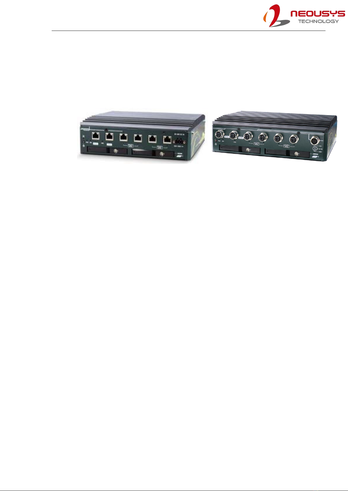
NRU-220S series is a one-stop AI NVR real-time inference and video transcoder powered by
NVIDIA Jetson AGX Orin. Its fanless design and wide temperature operation capability makes it
ideal for stationary or mobile deployment applications.
NRU-220S
NRU-222S
Powered by NVIDIA® Jetson AGX Orin™32GB/ 64GB system-on-module (SOM), it comprises
an Ampere GPU with up to 2048 CUDA cores, 64 Tensor cores, 2x NVDLA 2.0 Engines that
offer a total of 275 sparse TOPS (INT8) AI inference and video transcoding capability of up to
twenty-two 1080P video streams simultaneously.
NRU-220S offers four 802.3at PoE+ ports sharing 1 Gigabit bandwidth; each port can supply up
to 25.5W of power to IP cameras. The additional two 2.5GbE ports is ideal for surveillance
applications requiring more IP camera connections, or higher bandwidth connections to the
backend. In addition to 64GB eMMC on the Orin module and an M.2 2280 NVMe socket for fast
SSD read/write, NRU-220S is equipped with two front-accessible 2.5" SSD trays for storage
expansion. It also has two mini-PCIe sockets for CAN/ COM/ WiFi modules and one M.2 B key
socket for 4G LTE/ 5G NR mobile communications.
In addition to the above mentioned connectivity, the system also includes a wide range of
NVIDIA AI tools, and modern deep learning frameworks. NRU-220S brings real-time video
inference to the edge for surveillance, predictive maintenance, and intelligent transportation
system (ITS) applications. Furthermore, with Neousys' unique damping bracket design, ignition
power control, and 8-48V wide-range DC power input, NRU- 220S is also ideal for in-vehicle
deployment. Last but not least, NRU-220S comes with a derivative model, NRU-222S,
incorporating M12 connectors for applications in shock and vibration environments that require
extreme rugged connections, such as for agriculture, construction, and mining machinery.
NRU-220S series is Neousys' response to edge AI performance demands in a compact form
factor with fanless wide-temperature operation.

NRU-220S Series
11
1.1 NRU-220S Specifications
System Core
Processor
NVIDIA®Jetson AGX Orin™System-on-Module (SOM), comprising NVIDIA®Ampere
GPU and Arm Cortex-A78AE CPU
Memory
32GB/ 64GB LPDDR5 (AGX Orin 32GB/ 64GB) @ 3200 MHz on SOM
eMMC
64GB eMMC 5.1 on SOM
Panel I/O Interface
Ethernet port
6x RJ45 Gigabit ports with screw-lock
Port 1/ 2: 2.5GbE ports by Intel® I225
Port 3-6: GbE ports (share 1 Gbps total bandwidth)
PoE Capability
IEEE 802.3bt PoE+ PSE for ports 3-6 (maximum 100W total power budget)
USB
1x USB 3.2 Gen2 port
2x USB 2.0 ports
1x USB Type C (Debug Only)
Video Port
1x DisplayPort, supporting 3840x2160 at 60Hz
Serial Port
1x Isolated RS-485 port and 2x RS-232 ports
CAN bus
2x CAN 2.0 port
Isolated DIO
4-CH isolated DI and 4-CH isolated DO
Internal I/O Interface
Mini PCI Express
1x full-size mini PCI Express socket (PCIe + USB 2.0) for WiFi 6, or CAN modules
1x full-size mini PCI Express socket (USB 2.0) for GNSS or 4G LTE modules
M.2
1x M.2 3042/3052 B key (USB 3.2 Gen 1 + USB 2.0) for 4G/5G module with dual SIM
support
Storage Interface
SATA
2x front-accessible 2.5”7mm HDD/ SSD
M.2 NVMe
1x M.2 2280 M key NVMe socket (PCIe Gen4x4)
Power Supply
DC Input
1x 3-pin pluggable terminal block for 8V to 48V DC input and ignition power control (V+/

NRU-220S Series
12
GND/ IGN)
Mechanical
Dimension
230 mm (W) x 173 mm (D) x 66 mm (H)
Weight
2.6kg (excluding damping bracket)
Mounting
Wall-mount with damping bracket
Environmental
Operating
Temperature
-25°C ~ 70°C with passive cooling (30W TDP mode)*
Storage
Temperature
-40°C ~ 85°C
Humidity
10% ~ 90%, non-condensing
Vibration
Operating, MIL-STD-810H, Method 514.8, Category 4
Shock
Operating, MIL-STD-810H, Method 516.8, Procedure I
EMC
CE/FCC Class A, according to EN 55032 & EN 55035
EN 50121-3 (EN 50155:2017, Clause 13.4.8)
* For sub-zero and over 60°C operating temperature, a wide temperature Solid State Disk (SSD)
is required.

NRU-220S Series
13
1.2 NRU-222S Specifications
System Core
Processor
NVIDIA®Jetson AGX Orin™System-on-Module (SOM), comprising NVIDIA®Ampere
GPU and Arm Cortex-A78AE CPU
Memory
32GB/ 64GB LPDDR5 (AGX Orin 32GB/ 64GB) @ 3200 MHz on SOM
eMMC
64GB eMMC 5.1 on SOM
Panel I/O Interface
Ethernet port
6x M12 X-coded 8-pin
Port 1/ 2: 2.5GbE ports by Intel® I225
Port 3-6: GbE ports (share 1 Gbps total bandwidth)
PoE Capability
IEEE 802.3bt PoE+ PSE for ports 3-6 (maximum 100W total power budget)
USB
1x USB 3.2 Gen1 port
2x USB 2.0 ports
1x USB Type C (Debug Only)
Video Port
1x DisplayPort, supporting 3840x2160 at 60Hz
Serial Port
1x Isolated RS-485 port and 2x RS-232 ports
CAN bus
2x CAN 2.0 port
Isolated DIO
4-CH isolated DI and 4-CH isolated DO
Internal I/O Interface
Mini PCI Express
1x full-size mini PCI Express socket (PCIe + USB 2.0) for WiFi 6, or CAN modules
1x full-size mini PCI Express socket (USB 2.0) for GNSS or 4G LTE modules
M.2
1x M.2 3042/3052 B key (USB 3.2 Gen 1 + USB 2.0) for 4G/5G module with dual SIM
support
Storage Interface
SATA
2x front-accessible 2.5”7mm HDD/ SSD
M.2 NVMe
1x M.2 2280 M key socket (PCIe Gen4x4) for NVMe SSD
Power Supply
DC Input
1x M12 A-coded 5-pin for 8V to 48V DC input and ignition power control (V+/ GND/

NRU-220S Series
14
IGN)*
Mechanical
Dimension
230 mm (W) x 173 mm (D) x 66 mm (H)
Weight
2.6kg (excluding damping bracket)
Mounting
Wall-mount with damping bracket
Environmental
Operating
Temperature
-25°C ~ 70°C with passive cooling (30W TDP mode)**
Storage
Temperature
-40°C ~ 85°C
Humidity
10% ~ 90%, non-condensing
Vibration
IEC61373:2010, Category 1, Class B Body Mounted (part of EN 50155)
Shock
IEC61373:2010, Category 1, Class B Body Mounted (part of EN 50155)
EMC
CE/FCC Class A, according to EN 55032 & EN 55035
EN 50121-3 (EN 50155:2017, Clause 13.4.8)
* Due to the M12 DC input current limit, the allowable DC input range of the NRU-222S varies
based on the system load: System load under 60W, the required DC input range is 8V to 48V
System load between 60W to 160W, the required DC input range is 20V to 48V
** For sub-zero and over 60°C operating temperature, a wide temperature Solid State Disk (SSD)
is required.

NRU-220S Series
15
1.3 Dimension of NRU-220S Series
NOTE
All measurements are in millimeters (mm).
NRU-220S and NRU-222S share the same dimensions, therefore NRU-220S will be used for
demonstration purposes.
1.3.1 Front Panel View
1.3.2 Side Panel View

NRU-220S Series
16
1.3.3 Rear Panel View
1.3.4 Bottom View

NRU-220S Series
17
2 System Overview
Upon receiving and unpacking your NRU-220S series systems, please check immediately if the
package contains all the items listed in the following table. If any item(s) are missing or damaged,
please contact your local dealer or Neousys Technology.
2.1 NRU-220S Packing List
Item
Description
Qty
1
NRU-220S (If you ordered SSD/ HDD or add-on module, please verify
these items)
1
2
Accessory box, which contains
⚫Shock-absorbing grommet
⚫3-pin power terminal block
⚫Screw pack
⚫Wall mount damping bracket
⚫Standoff,M3,H4,L5 _ for M.2 3042/ 3052 B key module
8
1
1
1
1
2.2 NRU-222S Packing List
Item
Description
Qty
1
NRU-222S (If you ordered SSD/ HDD or add-on module, please verify
these items)
1
2
Accessory box, which contains
⚫Shock-absorbing grommet
⚫Screw pack
⚫Wall mount damping bracket
⚫Standoff,M3,H4,L5 _ for M.2 3042/ 3052 B key module
⚫M12 A5 to 3-pin Cord End 180 cm Cable _ for M12 A5 DC input
⚫Splicing Connector w/Lever 2-Pole inline _ For 180cm M12 A5 Cable
terminal end connection with DC source or ignition signal
8
1
1
1
1
3

NRU-220S Series
18
2.3 NRU-200S Series Front Panel
The front panel of the system features rich I/O ports, it has a 3-pin terminal block for DC input,
2.5GbE ports, GbE PoE ports, dual 2.5”HDD/SSD front-accessible trays, etc.
No.
Item
Description
1
Recovery
button
Use this button in conjunction with the power button to enter
Recovery mode
2
Power button
Use this button to turn on or force power off the system. It is also
used in conjunction with the recovery button to enter recovery mode.
3
System status
LED
Three system LEDs, power (PWR), ignition control (IGN), and
operating system (OS)
4
2.5GbE port
There are two 2.5Gb Ethernet ports with screw-lock mechanisms
5
GbE port
The four Gb Ethernet ports with screw-lock mechanisms are also
Power over Ethernet (PoE) ports
6
3-pin terminal
block (DC/
ignition input)
Compatible with DC power input from 8-48V, the terminal block is also
used for ignition signal input.
Two 2.5”front accessible HDD/ SSD trays supporting drives up to
7mm

NRU-220S Series
19
2.3.1 Recovery Button
In conjunction with the power button, the force recovery button is reserved for
engineering, system recovery, or reflash purposes.
2.3.2 Power Button
The power button is a non-latched switch for ATX mode on/off operation. Press to turn on the
system, PWR LED should light up and to turn off, you can either issue a shutdown command in
the OS, or just press the power button. In case of system halts, you can press and hold the power
button for 5 seconds to force-shutdown the system. Please note that there is a 5 seconds interval
between two on/off operations (i.e. once turning off the system, you will need to wait for 5
seconds to initiate another power-on operation).

NRU-220S Series
20
2.3.3 System Status LED
There are three LED indicators on the front panel: IGN, OS and PWR. The descriptions of these
LEDs are listed in the following table.
Indicator
Color
Description
PWR
Green
Power indicator, lit when the PCBA is powered on
IGN
Yellow
Ignition power control, lit when IGN signal is applied.
OS
Red
Lit when system is powered on, and booted into device tree
This manual suits for next models
1
Table of contents
Other Neousys Desktop manuals


