Neousys Nuvo-7160GC Series User manual

Neousys Technology Inc.
Nuvo-7160GC Series
Nuvo-7164GC Series
User Manual
Revision 1.0

Table of Contents
Table of Contents
Table of Contents...................................................................................................................2
Legal Information...................................................................................................................5
Contact Information...............................................................................................................6
Declaration of Conformity.....................................................................................................6
Copyright Notice....................................................................................................................7
Safety Precautions.................................................................................................................8
Service and Maintenance ......................................................................................................9
ESD Precautions....................................................................................................................9
About This Manual...............................................................................................................10
1Introduction
1.1 Product Specifications.............................................................................................12
1.1.1 Nuvo-7160GC Specifications............................................................................12
1.1.2 Nuvo-7164GC Specifications............................................................................14
1.2 Nuvo-7160GC Dimension.........................................................................................16
1.2.1 Nuvo-7160GC Front Panel View.......................................................................16
1.2.2 Nuvo-7160GC Rear Panel View .......................................................................16
1.2.3 Nuvo-7160GC Top View....................................................................................17
1.2.4 Nuvo-7160GC Bottom View..............................................................................18
1.3 Nuvo-7164GC Dimension.........................................................................................19
1.3.1 Nuvo-7164GC Front Panel View.......................................................................19
1.3.2 Nuvo-7164GC Rear Panel View .......................................................................19
1.3.3 Nuvo-7164GC Top View....................................................................................20
1.3.4 Nuvo-7164GC Bottom View..............................................................................21
2System Overview
2.1 Nuvo-7160GC Packing List......................................................................................22
2.2 Nuvo-7164GC Packing List......................................................................................22
2.3 Front Panel I/O..........................................................................................................23
2.3.1 USB3.1 Gen 2 Port...........................................................................................24
2.3.2 USB3.1 Gen 1 Port...........................................................................................24
2.3.3 DVI Port............................................................................................................25
2.3.4 VGA Port...........................................................................................................26
2.3.5 DisplayPort........................................................................................................27
2.3.6 Micro-SIM (3FF) 1 & 2 Slots..............................................................................28
2.3.7 Ethernet Port/ PoE+..........................................................................................29
2.3.8 Reset Button.....................................................................................................30
2.3.9 LED Indicators ..................................................................................................30
2.3.10 Power Button ....................................................................................................31
2.3.11 Cassette Module...............................................................................................32
2.4 Rear Panel I/O...........................................................................................................33
2.4.1 4-Pole 3.5mm Headphone/ Microphone Jack...................................................34
2.4.2 COM Ports........................................................................................................35
2.4.3 3-Pin Terminal Block for DC and Ignition Input..................................................36
2.4.4 3-Pin Remote On/ Off .......................................................................................36
2.5 Internal I/O Functions...............................................................................................37
2.5.1 Clear CMOS Button..........................................................................................37
2.5.2 Dual SODIMM DRAM Slot................................................................................38
2.5.3 Dual Mode mSATA/ mini-PCIe Socket & Pin Definition.....................................39
2.5.4 M.2 2242 (B Key), Mini-SIM Card Slot & Pin Definition.....................................41
2.5.5 SATA Ports........................................................................................................43
2.5.6 DIP Switch ........................................................................................................44
2.5.7 On/ Off Ctrl & Status Output..............................................................................45
2.5.8 Internal USB 2.0 Port........................................................................................46
2.5.9 M.2 2280 (M Key) Slot for NVMe SSD or OptaneTM Memory............................47
2.5.10 MezIOTM Interface & Pin Definition....................................................................49

Table of Contents
3
3System Installation
3.1 Disassembling the System......................................................................................52
3.2 Installing Internal Components...............................................................................56
3.2.1 CPU Installation Procedure...............................................................................56
3.2.2 DDR4 SO-DIMM Installation.............................................................................62
3.2.3 mPCIe Module, Mini-SIM (2FF) Card and Antennae Installation.......................64
3.2.4 M.2 2242 (B Key) Module and Micro-SIM (3FF) Card Installation.....................66
3.2.5 M.2 2280 NVMe SSD or Intel®OptaneTM Memory Installation..........................68
3.2.6 MezIOTM Module Installation (Optional)............................................................70
3.2.7 HDD/ SSD Installation.......................................................................................73
3.2.8 Ethernet/ PoE+ Port Panel Screw Fix...............................................................76
3.3 Nuvo-7160GC Graphics Card Installation ..............................................................77
3.4 Nuvo-7164GC Tesla Inference Accelerator Installation.........................................82
3.5 Installing the System Enclosure .............................................................................90
3.6 Wall Mount and Anti-vibration Damping Bracket Installation...............................93
3.6.1 Wall Mount Bracket Installation.........................................................................93
3.6.2 Anti-vibration Damping Bracket Installation (Optional)......................................95
3.7 Powering On the System .........................................................................................96
3.7.1 Powering On Using the Power Button...............................................................96
3.7.2 Powering On Using External Non-latched Switch.............................................97
3.7.3 Powering On Using Wake-on-LAN....................................................................98
4System Configuration
4.1 BIOS Settings .........................................................................................................100
4.1.1 COM Port Configuration..................................................................................101
4.1.2 COM Port High Speed Mode..........................................................................102
4.1.3 Delay for PEG Initialization.............................................................................103
4.1.4 SATA Configuration.........................................................................................104
4.1.5 Fan Control Configuration...............................................................................106
4.1.6 TPMAvailability............................................................................................... 111
4.1.7 Auto Wake on S5............................................................................................112
4.1.8 Power OnAfter Power Failure Option.............................................................113
4.1.9 Power & Performance (CPU SKU Power Configuration)................................114
4.1.10 Wake on LAN Option ......................................................................................115
4.1.11 Boot Menu ......................................................................................................116
4.1.12 Boot Type (Legacy/ UEFI)...............................................................................118
4.1.13 Position New Boot Device...............................................................................119
4.1.14 Watchdog Timer for Booting............................................................................120
4.1.15 Legacy/ UEFI Boot Device..............................................................................121
4.2 AMT Configuration.................................................................................................122
4.3 RAID Configuration................................................................................................123
4.3.1 Legacy Mode RAID Configuration...................................................................123
4.3.2 UEFI Mode RAID Configuration......................................................................129
5OS Support and Driver Installation
5.1 Operating System Compatibility...........................................................................139
5.2 Driver Installation...................................................................................................140
5.2.1 Install Drivers Automatically............................................................................140
5.2.2 Install Drivers Manually...................................................................................141
5.3 Driver Installation for Watchdog Timer Control...................................................142
5.4 Intel®OptaneTM Memory BIOS Setup and Driver Installation..............................143
Appendix A Using WDT & DIO
WDT and DIO Library Installation.....................................................................................153
WDT Functions...................................................................................................................155
InitWDT................................................................................................................................155
SetWDT ...............................................................................................................................155
StartWDT.............................................................................................................................156

Safety Precautions
4
ResetWDT ...........................................................................................................................156
StopWDT .............................................................................................................................156
Appendix B PoE On/ Off Control
GetStatusPoEPort..............................................................................................................157
EnablePoEPort...................................................................................................................158
DisablePoEPort..................................................................................................................159

Legal Information
Legal Information
All Neousys Technology Inc. products shall be subject to the latest Standard
Warranty Policy
Neousys Technology Inc. may modify, update or upgrade the software, firmware or
any accompanying user documentation without any prior notice. Neousys
Technology Inc. will provide access to these new software, firmware or
documentation releases from download sections of our website or through our
service partners.
Before installing any software, applications or components provided by a third party,
customer should ensure that they are compatible and interoperable with Neousys
Technology Inc. product by checking in advance with Neousys Technology Inc.
Customer is solely responsible for ensuring the compatibility and interoperability of
the third party’s products. Customer is further solely responsible for ensuring its
systems, software, and data are adequately backed up as a precaution against
possible failures, alternation, or loss.
For questions in regards to hardware/ software compatibility, customers should
contact Neousys Technology Inc. sales representative or technical support.
To the extent permitted by applicable laws, Neousys Technology Inc. shall NOT be
responsible for any interoperability or compatibility issues that may arise when (1)
products, software, or options not certified and supported; (2) configurations not
certified and supported are used; (3) parts intended for one system is installed in
another system of different make or model.

Contact Information/ Declaration of Conformity
Contact Information
Headquarters
(Taipei, Taiwan)
Neousys Technology Inc.
15F, No.868-3, Zhongzheng Rd., Zhonghe Dist., New Taipei City, 23586, Taiwan
Tel: +886-2-2223-6182 Fax: +886-2-2223-6183 Email, Website
Americas
(Illinois, USA)
Neousys Technology America Inc.
3384 CommercialAvenue, Northbrook, IL 60062, USA
Tel: +1-847-656-3298Email, Website
China Neousys Technology (China) Ltd.
Room 612, Building 32, Guiping Road 680, Shanghai
Tel: +86-2161155366Email, Website
Declaration of Conformity
FCC This equipment has been tested and found to comply with the limits for a Class
A digital device, pursuant to part 15 of the FCC Rules. These limits are
designed to provide reasonable protection against harmful interference when
the equipment is operated in a commercial environment. This equipment
generates, uses, and can radiate radio frequency energy and, if not installed
and used in accordance with the instruction manual, may cause harmful
interference to radio communications. Operation of this equipment in a
residential area is likely to cause harmful interference in which case the user will
be required to correct the interference at own expense.
CE The product(s) described in this manual complies with all applicable European
Union (CE) directives if it has a CE marking. For computer systems to remain
CE compliant, only CE-
compliant parts may be used. Maintaining CE
compliance also requires proper cable and cabling techniques.

Copyright Notice
Copyright Notice
All rights reserved. This publication may not be reproduced, transmitted,
transcribed, stored in a retrieval system, or translated into any language or
computer language, in any form or by any means, electronic, mechanical,
magnetic, optical, chemical, manual or otherwise, without the prior written
consent of Neousys Technology, Inc.
Disclaimer This manual is intended to be used as an informative guide only and is subject
to change without prior notice. It does not represent commitment from Neousys
Technology Inc. Neousys Technology Inc. shall not be liable for any direct,
indirect, special, incidental, or consequential damages arising from the use of
the product or documentation, nor for any infringement on third party rights.
Patents and
Trademarks
Neousys, the Neousys logo, Expansion Cassette, MezIOTM are registered
patents and trademarks of Neousys Technology, Inc.
Windows is a registered trademark of Microsoft Corporation.
Intel®, Core™ are registered trademarks of Intel Corporation
NVIDIA®is a registered trademark of NVIDIA Corporation
All other names, brands, products or services are trademarks or registered
trademarks of their respective owners.

Safety Precautions
Safety Precautions
Read these instructions carefully before you install, operate, or transport the
system.
Install the system or DIN rail associated with, at a sturdy location
Install the power socket outlet near the system where it is easily accessible
Secure each system module(s) using its retaining screws
Place power cords and other connection cables away from foot traffic. Do not
place items over power cords and make sure they do not rest against data
cables
Shutdown, disconnect all cables from the system and ground yourself before
touching internal modules
Ensure that the correct power range is being used before powering the device
Should a module fail, arrange for a replacement as soon as possible to
minimize down-time
If the system is not going to be used for a long time, disconnect it from mains
(power socket) to avoid transient over-voltage

Service and Maintenance/ ESD Precautions
Service and Maintenance
ONLY qualified personnel should service the system
Shutdown the system, disconnect the power cord and all other connections
before servicing the system
When replacing/ installing additional components (expansion card, memory
module, etc.), insert them as gently as possible while assuring proper
connector engagement
ESD Precautions
Handle add-on module, motherboard by their retention screws or the module’s
frame/ heat sink. Avoid touching the PCB circuit board or add-on module
connector pins
Use a grounded wrist strap and an anti-static work pad to discharge static
electricity when installing or maintaining the system
Avoid dust, debris, carpets, plastic, vinyl and styrofoam in your work area.
Do not remove any module or component from its anti-static bag before
installation
About This Manual
About This Manual
This manual introduces Neousys Nuvo-7160GC series featuring Intel®8th Gen
Core™ i hexa core 35W/ 65W LGA1151 processors. The Nuvo-7160GC system
supports an NVIDIA®graphics card up to 120W while Nuvo-7164GC supports an
NVIDIA® Tesla®P4/ T4 for advanced inference capabilities.
The guide also demonstrates the system’s installation procedures.
Revision History
Version Date Description
1.0 Jul. 2019 Initial release
Nuvo-7160GC/ Nuvo-7164GC Series
11
1 Introduction
Nuvo-7160GC series is a ruggedized GPU-aided AI inference platform designed for modern
machine learning applications such as autonomous driving, facial recognition, vision
inspection and recommendation services. It supports up to a 120W GPU, delivering 4~6
TFLOPS computing power for inference, as well as Intel®8th Gen CoreTM 6-core/ 12-thread
CPU, offering over extra 50% CPU performance enhancement over previous generations.
The Nuvo-7164GC supports NVIDIA®Tesla®P4/ T4 delivering up to 40X higher inference
capability compared to just CPUs. Nuvo-7164GC supports Tesla®P4 GPU, featuring 5.5
TFLOPS in FP32 and Tesla®T4 GPU, featuring 8.1 TFLOPS in FP32 and 130 TOPs in INT8
for real-time inference based on trained neural network model.
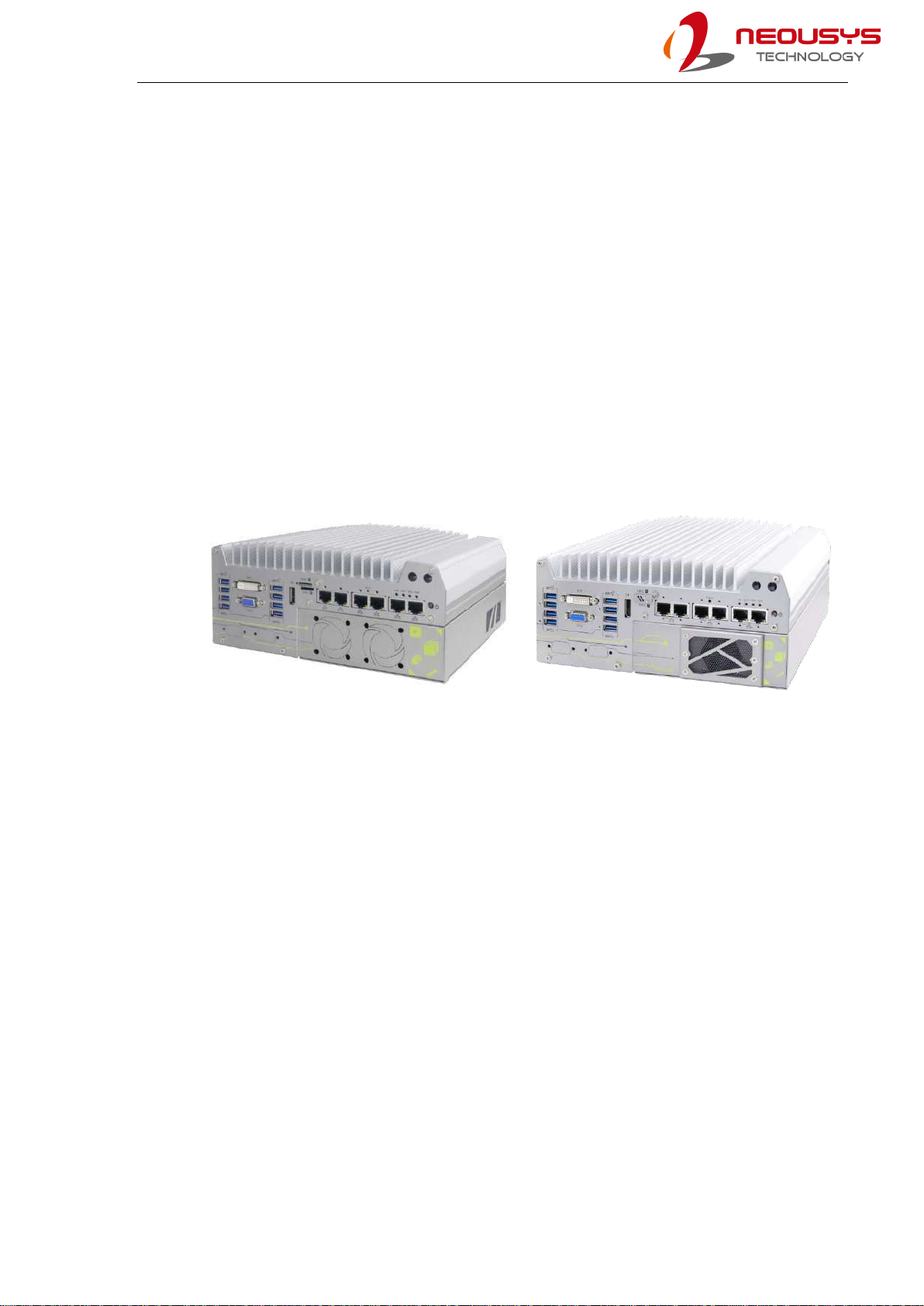
Nuvo-7160GC Nuvo-7164GC
Thanks to Neousys’ patented Cassette design and ingenious ventilation mechanism,
Nuvo-7160GC series is capable of effectively dissipating the heat generated by the GPU. By
introducing the guided airflow from intake to exhaust with powerful fans featuring smart fan
control, it allows an NVIDIA®120W GPU to operate at 60°C ambient temperature under 100%
GPU loading.
The Nuvo-7164GC follows a similar Cassette design but instead guides the air to flow directly
over the heatsink of NVIDIA® Tesla P4/ T4 to sustain 100% GPU loading up to 60ºC operating
temperature.
Nuvo-7160GC/ Nuvo-7164GC series incorporate rich I/O functions such as USB 3.1 Gen2/
Gen1, GbE, COM and MezIOTM interface in its restricted footprint. It also leverages
cutting-edge M.2 NVMe technology to support over 2000 MB/s disk read/write speed or utilize
Intel®OptaneTM memory to boost the performance of your traditional hard disk drive. Neousys
Nuvo-7160GC/ Nuvo-7164GC series are ideal solutions for emerging edge computing by
combining exceptional CPU and GPU performances.

Nuvo-7160GC/ Nuvo-7164GC Series
12
1.1 Product Specifications
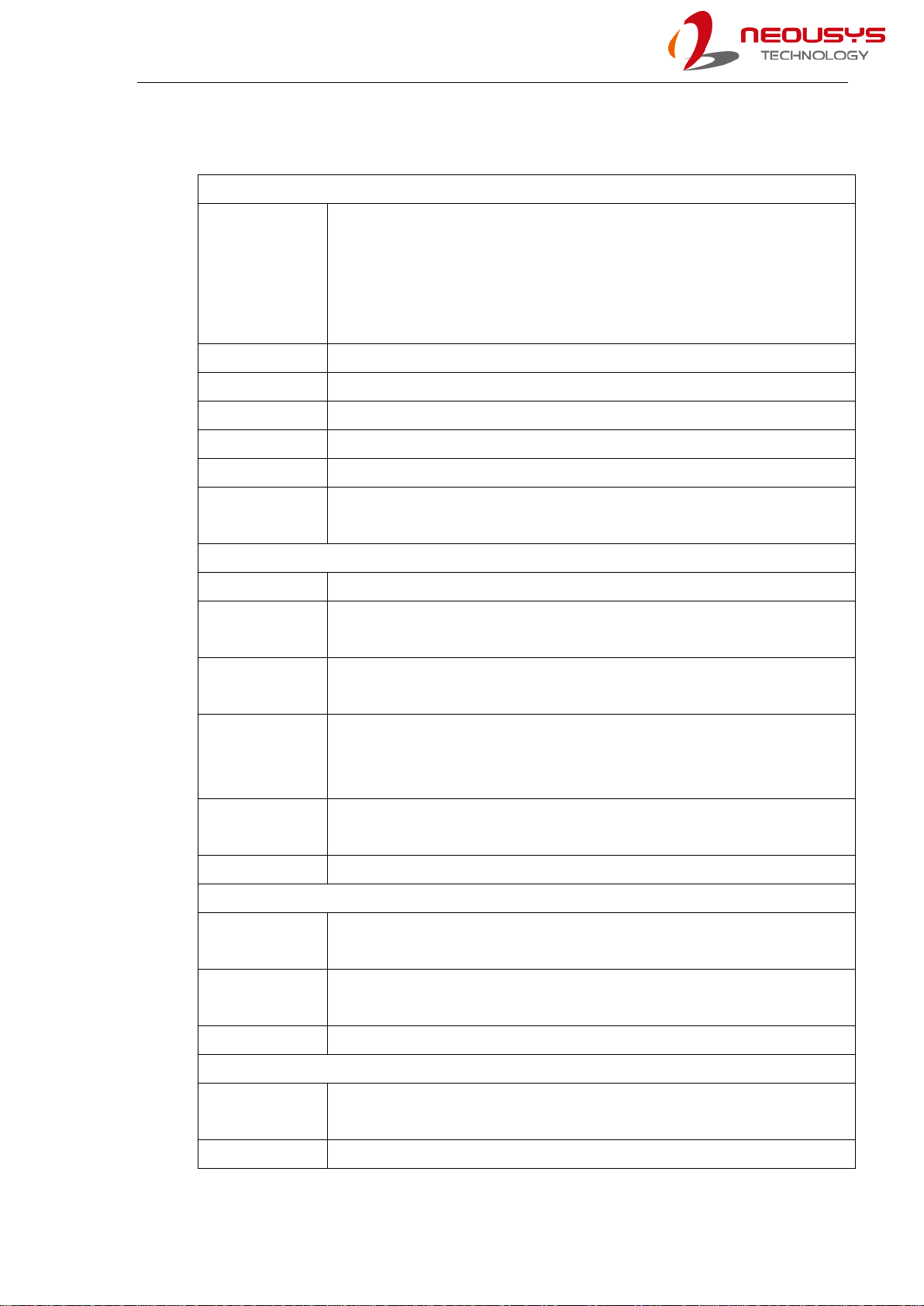
1.1.1 Nuvo-7160GC Specifications
System Core
Processor
Supporting Intel®8th Gen Coffee Lake 6 core CPU (LGA1151 socket,
65W/ 35W TDP)
- Intel® Core™i7-8700/ i7-8700T
- Intel® Core™i5-8500/ i5-8500T
- Intel® Core™ i3-8100/ i3-8100T
Chipset Intel®Q370 Platform Controller Hub
Graphics Integrated Intel®UHD Graphics 630
Memory Up to 64GB DDR4 2666/ 2400 SDRAM (two SODIMM slots)
AMT Supports AMT 12.0
TPM Supports TPM 2.0
I/O Interface
Ethernet port 6x Gigabit Ethernet ports (I219 and 5x I210)
PoE+ Optional IEEE 802.3at PoE+ PSE for Port 3 ~ Port 6
100 W total power budget
USB 4x USB 3.1 Gen2 (10 Gbps) ports
4x USB 3.1 Gen1 (5 Gbps) ports
Video Port
1x VGA connector, supporting 1920 x 1200 resolution
1x DVI-D connector, supporting 1920 x 1200 resolution
1x DisplayPort connector, supporting 4096 x 2304 resolution
Serial Port 2x software-programmable RS-232/ 422/ 485 ports (COM1/ COM2)
2x RS-232 ports (COM3/ COM4)
Audio 1x 3.5mm jack for mic-in and speaker-out
Storage Interface
SATA HDD 2x internal SATA port for 2.5” HDD/ SSD (support up to 15mm thickness),
supporting RAID 0/1
M.2 NVMe 1x M.2 2280 M key NVMe socket (PCIe Gen3 x4 and SATA signal) for
NVMe/ SATA SSD or Intel®OptaneTM memory installation
mSATA 1x full-size mSATA port (mux with mini-PCIe)
Internal Expansion Bus
PCI Express
1x PCIe x16 slot@Gen3, 16-lanes PCIe signals in Cassette for
installing NVIDIA®120W GPU (Max. graphics card dimension is 188
mm(L) x 121 mm(W), dual slot allocation)

Nuvo-7160GC/ Nuvo-7164GC Series
13
* R.O.C Patent No. M534371/ M456527
** For i7-8700 running at 65W mode, the highest operating temperature shall be limited to
50°C and thermal throttling may occur when sustained full-loading applied. Users can
configure CPU power in BIOS to obtain higher operating temperature.
*** For sub-zero operating temperature, a wide temperature HDD or Solid State Disk (SSD) is
required.
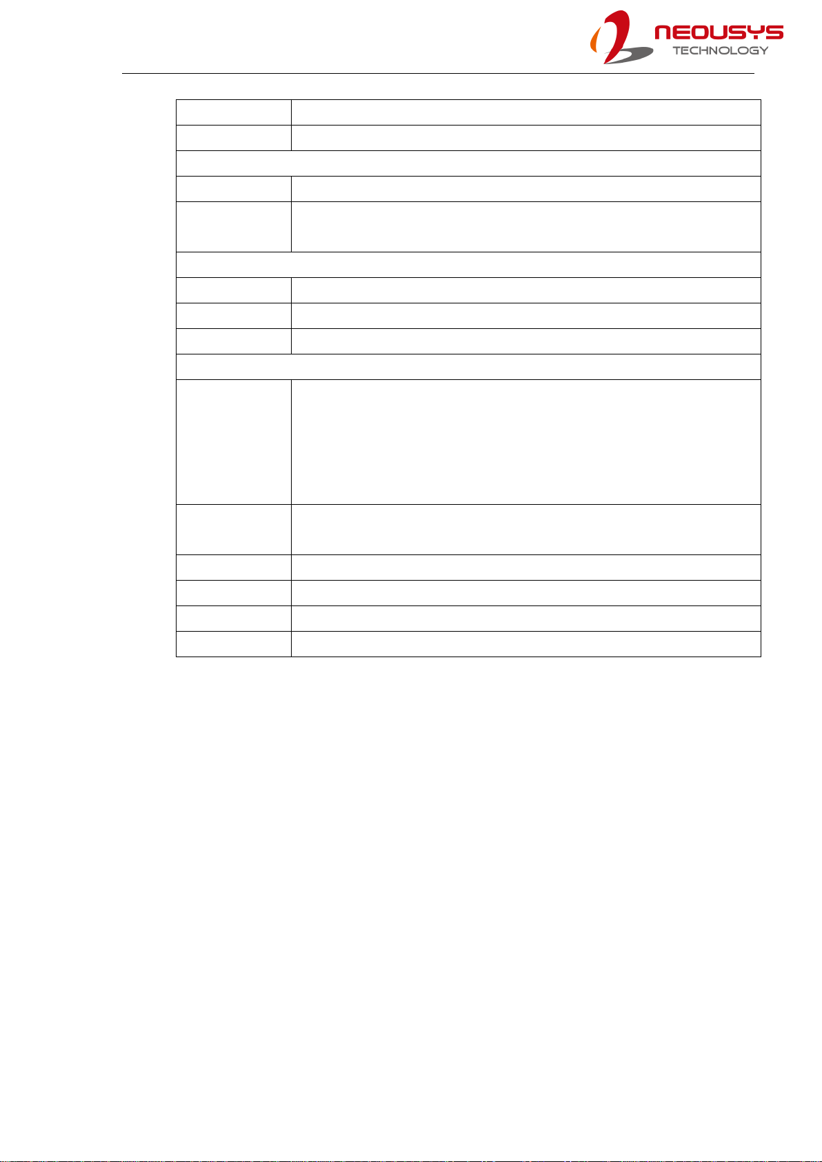
Mini PCI-E 1x full-size mini PCI Express socket with internal SIM socket (mux with
mSATA)
M.2 1x M.2 2242 B key socket with dual front-accessible SIM sockets,
supporting dual SIM mode with selected M.2 LTE module
Expandable I/O 1x MezIOTM expansion port for Neousys MezIOTM modules
Power Supply
DC Input 1x 3-pin pluggable terminal block for 8~35VDC input
Remote Ctrl. &
Status Output 1x 3-pin pluggable terminal block for remote control and PWR LED output
Maximum
Power
Consumption
With 120W NVIDIA®GPU
With i7-8700 (35W mode): 211W (Max.) @ 24V
With i7-8700 (65W mode): 240W (Max.) @ 24V
Mechanical
Dimension 240mm (W) x 225 mm (D) x111 mm (H)
Weight 4.5 Kg (including CPU, GPU, memory and HDD)
Mounting Wall-mount (standard) or DIN-Rail mounting (optional)
Environmental
Operating
Temperature
With 35W CPU and 120W GPU
-25°C ~ 60°C **
With 65W CPU and 120W GPU
-25°C ~ 60°C */** (configured as 35W TDP mode)
-25°C ~ 50°C */** (configured as 65W TDP mode)
Storage
Temperature -40°C ~85°C
Humidity 10%~90% , non-condensing
Vibration Operating, MIL-STD-810G, Method 514.6, Category 4
Shock Operating, MIL-STD-810G, Method 516.6, Procedure I, Table 516.6-II
EMC CE/FCC Class A, according to EN 55032 & EN 55024
Nuvo-7160GC/ Nuvo-7164GC Series
14
1.1.2 Nuvo-7164GC Specifications
System Core
Processor
Supporting Intel®8th Gen Coffee Lake 6 core CPU (LGA1151 socket,
65W/ 35W TDP)
- Intel® Core™i7-8700/ i7-8700T
- Intel® Core™i5-8500/ i5-8500T
- Intel® Core™ i3-8100/ i3-8100T
Chipset Intel®Q370 Platform Controller Hub
Graphics Integrated Intel®UHD Graphics 630
Memory Up to 64GB DDR4 2666/ 2400 SDRAM (two SODIMM slots)
AMT Supports AMT 12.0
TPM Supports TPM 2.0
AI Inference
Accelerator
Supports NVIDIA®Tesla®P4/ T4 inference accelerator (1x PCIe x16
slot @ Gen3 in Cassette module)
I/O Interface
Ethernet port 6x Gigabit Ethernet ports (I219 and 5x I210)
PoE+ Optional IEEE 802.3at PoE+ PSE for Port 3 ~ Port 6
100 W total power budget
USB 4x USB 3.1 Gen2 (10 Gbps) ports
4x USB 3.1 Gen1 (5 Gbps) ports
Video Port
1x VGA connector, supporting 1920 x 1200 resolution
1x DVI-D connector, supporting 1920 x 1200 resolution
1x DisplayPort connector, supporting 4096 x 2304 resolution
Serial Port 2x software-programmable RS-232/ 422/ 485 ports (COM1/ COM2)
2x RS-232 ports (COM3/ COM4)
Audio 1x 3.5mm jack for mic-in and speaker-out
Storage Interface
SATA HDD 2x internal SATA port for 2.5” HDD/ SSD (support up to 15mm thickness),
supporting RAID 0/1
M.2 NVMe 1x M.2 2280 M key NVMe socket (PCIe Gen3 x4 and SATA signal) for
NVMe/ SATA SSD or Intel®OptaneTM memory installation
mSATA 1x full-size mSATA port (mux with mini-PCIe)
Internal Expansion Bus
Mini PCI-E 1x full-size mini PCI Express socket with internal SIM socket (mux with
mSATA)
M.2 1x M.2 2242 B key socket with dual front-accessible SIM sockets,
Nuvo-7160GC/ Nuvo-7164GC Series
15
* R.O.C Patent No. M534371/ M456527
** For i7-8700 running at 65W mode, the highest operating temperature shall be limited to
50°C and thermal throttling may occur when sustained full-loading applied. Users can
configure CPU power in BIOS to obtain higher operating temperature.
*** For sub-zero operating temperature, a wide temperature HDD or Solid State Disk (SSD) is
required.
supporting dual SIM mode with selected M.2 LTE module
Expandable I/O 1x MezIOTM expansion port for Neousys MezIOTM modules
Power Supply
DC Input 1x 3-pin pluggable terminal block for 8~35VDC input
Remote Ctrl. &
Status Output 1x 3-pin pluggable terminal block for remote control and PWR LED output
Mechanical
Dimension 240mm (W) x 225 mm (D) x111 mm (H)
Weight 4.5 Kg (including CPU, GPU, memory and HDD)
Mounting Wall-mount (standard) or DIN-Rail mounting (optional)
Environmental
Operating
Temperature
With 35W CPU and NVIDIA®Tesla P4/ T4 GPU
-25°C ~ 60°C **
With 65W CPU and NVIDIA®Tesla P4/ T4 GPU
-25°C ~ 60°C */** (configured as 35W TDP mode)
-25°C ~ 50°C */** (configured as 65W TDP mode)
Storage
Temperature -40°C ~85°C
Humidity 10%~90% , non-condensing
Vibration Operating, MIL-STD-810G, Method 514.6, Category 4
Shock Operating, MIL-STD-810G, Method 516.6, Procedure I, Table 516.6-II
EMC CE/FCC Class A, according to EN 55032 & EN 55024
Nuvo-7160GC/ Nuvo-7164GC Series
16
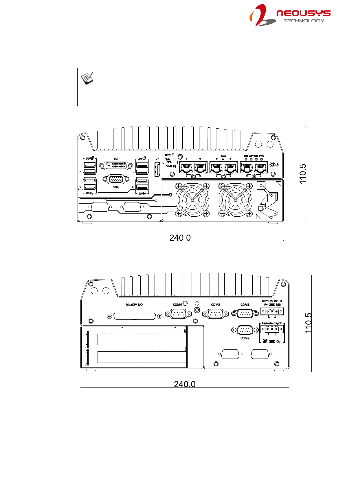
1.2 Nuvo-7160GC Dimension
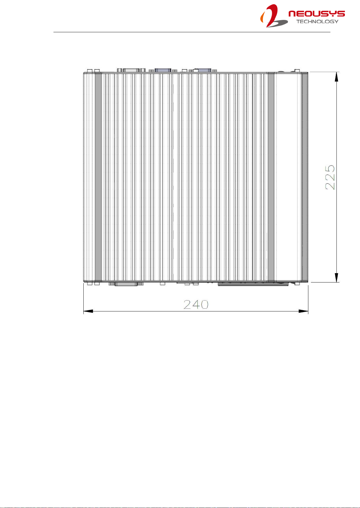
NOTE
All measurements are in millimeters (mm).
1.2.1 Nuvo-7160GC Front Panel View
1.2.2 Nuvo-7160GC Rear Panel View
Nuvo-7160GC/ Nuvo-7164GC Series
17
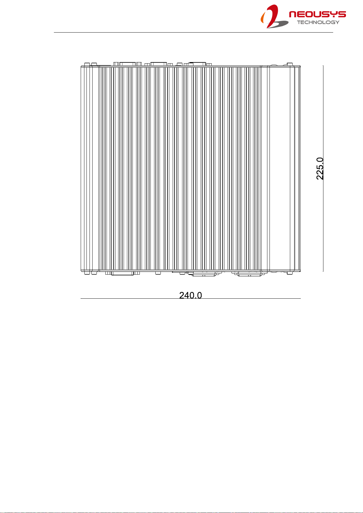
1.2.3 Nuvo-7160GC Top View
Nuvo-7160GC/ Nuvo-7164GC Series
18
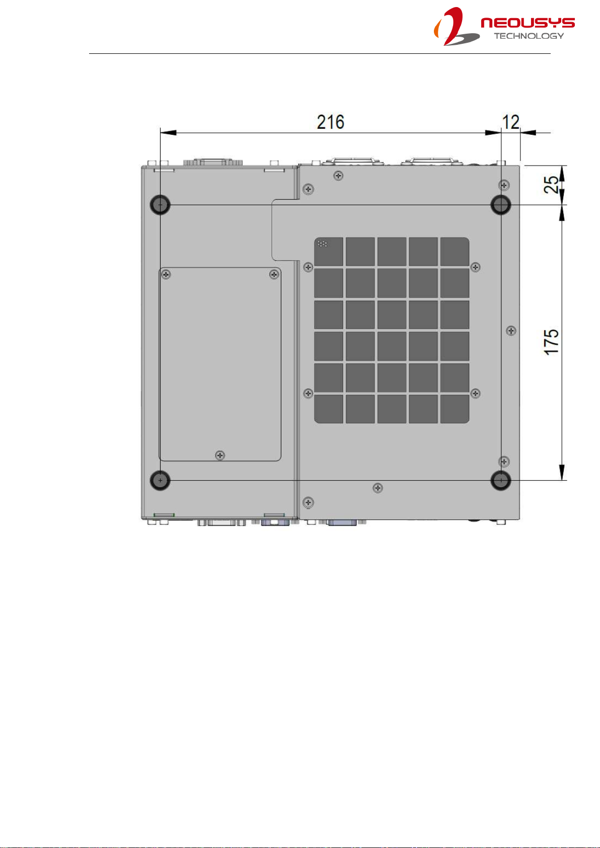
1.2.4 Nuvo-7160GC Bottom View
Nuvo-7160GC/ Nuvo-7164GC Series
19
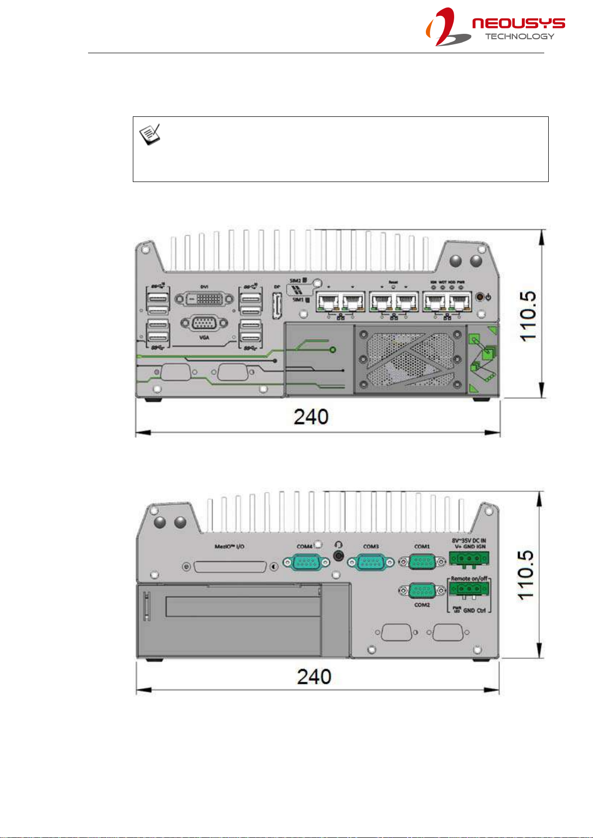
1.3 Nuvo-7164GC Dimension
NOTE
All measurements are in millimeters (mm).
1.3.1 Nuvo-7164GC Front Panel View
1.3.2 Nuvo-7164GC Rear Panel View
Nuvo-7160GC/ Nuvo-7164GC Series
20
1.3.3 Nuvo-7164GC Top View
This manual suits for next models
1
Table of contents
Other Neousys Desktop manuals


