Neoway N3830 User manual

N3830 Router
Operation Guide
Issue 2.0
Date 2018-10-07
Neoway Product Document

N3830 Router
Operation Guide
Copyright © Neoway Technology Co., Ltd
i
Copyright © Neoway Technology Co., Ltd 2018. All rights reserved.
No part of this document may be reproduced or transmitted in any form or by any means without prior
written consent of Neoway Technology Co., Ltd.
is the trademark of Neoway Technology Co., Ltd.
All other trademarks and trade names mentioned in this document are the property of their respective
holders.
Notice
This document provides guide for users to use N3830 Router.
This document is intended for system engineers (SEs), development engineers, and test engineers.
THIS GUIDE PROVIDES INSTRUCTIONS FOR CUSTOMERS TO DESIGN THEIR APPLICATIONS.
PLEASE FOLLOW THE RULES AND PARAMETERS IN THIS GUIDE TO DESIGN AND COMMISSION.
NEOWAY WILL NOT TAKE ANY RESPONSIBILITY OF BODILY HURT OR ASSET LOSS CAUSED BY
IMPROPER OPERATIONS.
THE INFORMATION IN THIS DOCUMENT IS SUBJECT TO CHANGE WITHOUT NOTICE DUE TO
PRODUCT VERSION UPDATE OR OTHER REASONS.
EVERY EFFORT HAS BEEN MADE IN PREPARATION OF THIS DOCUMENT TO ENSURE ACCURACY
OF THE CONTENTS, BUT ALL STATEMENTS, INFORMATION, AND RECOMMENDATIONS IN THIS
DOCUMENT DO NOT CONSTITUTE A WARRANTY OF ANY KIND, EXPRESS OR IMPLIED.
Neoway provides customers complete technical support. If you have any question, please contact your
account manager or email to the following email addresses:
Website: http://www.neoway.com

N3830 Router
Operation Guide
Copyright © Neoway Technology Co., Ltd
ii
Contents
1 Overview.................................................................................................... 4
2 Packing List ............................................................................................... 5
3 Industrial Application.................................................................................. 6
4 Functions and Features............................................................................. 7
5 Functional Interfaces ................................................................................. 8
6 N3830 Installation.................................................................................... 10
6.1 Installing SIM Card..................................................................................................................... 10
6.2 Installing Antennas ..................................................................................................................... 10
6.3 Installing Power Supply.............................................................................................................. 10
6.4 Installing Network Cable .............................................................................................................11
6.5 Terminal Definition...................................................................................................................... 12
6.6 Fixing and Installing Device ....................................................................................................... 12
6.6.1 Wall-mounted Installation .................................................................................................. 12
6.6.2 Wall-mounted Removal ..................................................................................................... 13
6.6.3 Guide-Rail Installation ....................................................................................................... 13
6.6.4 Guide-Rail Removal .......................................................................................................... 14
7 Work Mode .............................................................................................. 15
7.1 Router Connection ..................................................................................................................... 15
7.2 Web Access................................................................................................................................ 17
7.3 Current Status ............................................................................................................................ 18
7.4 WWAN Settings.......................................................................................................................... 19
7.5 LAN Settings .............................................................................................................................. 20
7.6 WLAN Settings........................................................................................................................... 20
7.7 NAT Settings .............................................................................................................................. 22
7.8 VPN Settings.............................................................................................................................. 22
7.9 Transparent Transmission Settings............................................................................................ 23
7.10 Device Management ................................................................................................................ 24
7.11 Exit ........................................................................................................................................... 25
8 LED Indicators ......................................................................................... 26

N3830 Router
Operation Guide
Copyright © Neoway Technology Co., Ltd
iii
About This Document
Scope
This document is applicable to N3830 Router series.
Audience
This document is intended for system engineers (SEs), development engineers, and test engineers.
Change History
Issue
Date
Change
Changed By
1.0
2017-09
Initial draft
Huang Shaowen
2.0
2018-09
Updated
Huang Shaowen
Conventions
Symbol
Indication
This warning symbol means danger. You are in a situation that could cause fatal
device damage or even bodily damage.
Means reader be careful. In this situation, you might perform an action that could
result in module or product damages.
Means note or tips for readers to use the module

N3830 Router
Operation Guide
Copyright © Neoway Technology Co., Ltd
4
1 Overview
N3830 industrial router is a high-performance industrial-grade wireless data transmission terminal that
adopts a Qualcomm 1.3GHz dominant-frequency ARM Cortex-A7 processor and was developed on
4G wireless network technology. It mainly applies to user data transmission business in various
industries, supports transparent serial-port data transmission and Ethernet routing, and can
implement all types of IO control to meet customers’ needs. This device also provides the cloud
platform management function, allowing users to remotely monitor and manage the device.

N3830 Router
Operation Guide
Copyright © Neoway Technology Co., Ltd
5
2 Packing List
Each piece of N3830 delivered out of the factory contains commonly used accessories (as shown in a
list of standard accessories) that suit customers’ sites. When you receive our product, please check it
carefully. If you find any accessory missing or damaged, please contact Neoway sales personnel.
Besides, Neoway can provide optional accessories to customers based on the specific characteristics
of their sites. For details, see the list of optional accessories.
Table 2-1 Standard accessories
Accessories
Quantity (PCS)
Description
N3830
1
4G wireless data transmission terminal
User manual
1
Instructions
4G magnetic antenna
1
4G antenna
Wi-Fi antenna
1
Wi-Fi antenna
Power supply terminal
1
One green power supply terminal
SMA RF dustproof cap
3
3 dustproof caps
Figure 2-2 Optional accessories
Accessories
Quantity
Description
Power adapter
1
VDC power adapter
GPS antenna
1
GPS antenna

N3830 Router
Operation Guide
Copyright © Neoway Technology Co., Ltd
6
3 Industrial Application
N3830 is a wireless gateway product developed based on the 4G cellular network standards. It
supports gigabit Ethernet and dual-serial-port simultaneous operation, supports WLAN, and provides
GPS positioning and LBS functions. It mainly applies to scenarios such as industrial IoT, device
sharing, and self-service equipment networking and provides stable and reliable wireless connections
that can be deployed quickly.
Figure 3-1 Industrial application solution
Network application
Self-service application
Automatic meters
Industrial application
N3830
监控
Business server
GNSS
positioning
手机
4G
工控机
Ethernet
RS232/RS485
WIFI/Ethernet
快递柜 自助机
无人售卖机 N3830
N3830
电表
水表 压力表
PLC RTU 触摸屏 N3830
RS232/RS485
4G
4G
4G
Base station
Operator network
Mgmt server
Status management
Business platform
Express
locker
Automatic
vending machine
Self-service
machine
Devices with
touchscreen
Water meter Electricity meter Pressure
gage
IPC Monitor Mobile
phone

N3830 Router
Operation Guide
Copyright © Neoway Technology Co., Ltd
7
4 Functions and Features
N3830 has the following functions and features:
Web UI configuration pages
Compatible with multiple modes and supports LTE, HSPA+, EV-DO, TD-SCDMA, GPRS/EDGE,
and CDMA 1X networks
CAT4 network, FDD:150Mbps (downlink)/50Mbps (uplink) TDD: 130Mbps (downlink) /35Mbps
(uplink)
WLAN (802.11b/g/n), AP mode or STATION mode
Dual-serial-port transparent data transmission, RS232 or RS85, and supports transmission
protocols TCP/UDP/HTTP
1 x gigabit Ethernet and supports DHCP
VPDN private network and VPN (PPTP\L2TP) tunnels
NAT, DMZ, and VPN transparent transmission
GPS positioning and LBS if required (optional)
OPEN LINUX and Modbus protocol development (optional)
Neoway platform for device fault alarm statistics, online upgrade, traffic monitoring, remote
configuration, etc. (optional)
Supports export of local logs
Operating temperature range: -30oC to +70oC
Storage temperature range: -40oC to +85oC
TF expansion, a maximum of 32GB Micro SD (Optional)
Customizable based on customers’ needs

N3830 Router
Operation Guide
Copyright © Neoway Technology Co., Ltd
8
5 Functional Interfaces
N3830 provides abundant user operation interfaces. The specific functional interfaces are described
as follows.
Figure 5-1 N3830 functional interfaces
The interfaces marked with digits are user interaction and operation interfaces.
These two figures are both front oblique views from either side of the device. The following
description is based on these two views.
Table 5-1 Definitions of N3830 functional interfaces
No.
Name
Function
Description
1
Wi-Fi
Wi-Fi antenna
interface
IEEE 802.11 b/g/n, with a maximum wireless rate of
150Mbit/s, SMA female connector to connect a
male-connector Wi-Fi antenna
2
CFG
Dialing switch
Extension function
3
SIM
SIM card socket
PUSH-PUSH style, chip surface facing downward, oblique
angle facing inward for insertion; supports 3FF:1.5*1.2cm
Micro SIM card, not hot-swappable
4
RST
Reset button
Pinhole reset button to reset the device in emergencies
5
LED
Six LED indicators
PWR, SYS, SIG, 485, LAN, DAT (for details, see Table 8-1)
6
4G
4G antenna
interface
SMA female connector to connect a male-connector 4G
antenna

N3830 Router
Operation Guide
Copyright © Neoway Technology Co., Ltd
9
7
GPS
GNSS antenna
interface
GPS, GLONASS, BDS
8
LAN
RJ45 interface
There are two indicators.
The yellow indicator on the left indicates the operating status;
and it is steady yellow during connection and flashes during
data transmission.
The green indicator on the right is a 100-megabyte network
indicator.
When it’s steady on, it indicates that the device is connected to
a 100-megabyte network.
When it’s off, it indicates that the device is connected to a
gigabit network, with the maximum transmission rate of
1.25Gb/s.
9
USB
USB interface
Standard type-A USB female socket interface, compliant with
USB2.0 standard, used only for upgrade
10
12-Pin
terminal
Multi-function
electrical interface
12-Pin plug-and-play interface, convenient for electrical
connection with multiple types of external equipment. For
details about interface definitions and electrical parameters,
see section 6.5.
Do not insert the SIM card into the slot from the incorrect side. Otherwise, the slot may be damaged,
resulting in device hardware faults.
Do not exert too much strength when inserting or removing the SIM card. Otherwise, the device may
be irreversibly damaged.

N3830 Router
Operation Guide
Copyright © Neoway Technology Co., Ltd
10
6 N3830 Installation
6.1 Installing SIM Card
Hold a SIM card with the chip surface downwards and insert it into the SIM card socket in an oblique
angle
The SIM card socket is in PUSH-PUSH style and supports 3FF:1.5*1.2cm Micro SIM card.
The device does not support SIM card hot-swap.
6.2 Installing Antennas
Point the connector of a 4G antenna to the 4G antenna interface, and gently rotate the movable part of
the metal interface until it's tight.
Install GPS and Wi-Fi antennas in a similar manner.
6.3 Installing Power Supply
Power supply requirement:
12 V DC (4.7-26 V DC); an 1A adapter is recommended.
Power supply installation procedure:
Loosen the lock screws on the terminal, insert the power supply cable into the terminal, and then
fasten the screws.

N3830 Router
Operation Guide
Copyright © Neoway Technology Co., Ltd
11
Figure 6-1 Power supply connection
6.4 Installing Network Cable
Connect a network cable directly to the computer.
Figure 6-2 Network cable connection

N3830 Router
Operation Guide
Copyright © Neoway Technology Co., Ltd
12
6.5 Terminal Definition
The pins of the terminal from left to right are defined as follows: GND1, OUT, IN2, IN1, 485A1, 485B1,
NC, NC, 485A2, 485B2, VCC, and GND2.
Table 6-1 Pin definition of the terminal
Name
Function description
Remarks
GND1
Ground
Ground
OUT
Output signal
OUT is the module signal output interface; drain output; normal
state: high-impedance state; supports a maximum of 30V
external input
IN1 and
IN2
Input signal
IN1 and IN2 are module signal input interfaces; pull-up input;
the external device is required to adopt drain output; the internal
10K resistance pulls up to 1.8V voltage.
485A1
and
485B1
RS485_1 interface
RS485 half-duplex communication interface. It supports
simultaneous connection with 32 devices in one bus, supports a
maximum transmission rate of 10Mbps, and fully complies with
the electrical specifications of RS485 and RS422 serial
protocols.
The hardware can be configured as: RS232 interface
NC
Reserved
(interface RS232)
By default, the configuration is not defined.
485A2
and
485B2
RS485_2 interface
RS485 half-duplex communication interface. It supports
simultaneous connection with 32 devices in one bus, supports a
maximum transmission rate of 10Mbps, and fully complies with
the electrical specifications of RS485 and RS422 serial
protocols.
VCC and
GND2
Power interface
VCC and GND2 are respectively the positive electrode and
negative electrode of the DC input. The DC supply voltage
ranges from 5V to 26V. 12V 1A DC power supply is
recommended.
6.6 Fixing and Installing Device
6.6.1 Wall-mounted Installation
Perform the following operations:
Step 1: Choose an installation position for the device.
N3830 Router
Operation Guide
Copyright © Neoway Technology Co., Ltd
13
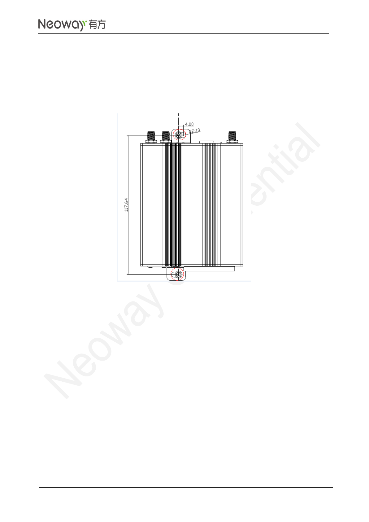
Step 2: Put the screws into the screw holes, and use a screwdriver to fix them onto the surface of the
installation position.
The red circles in Figure 6-3 marks the areas for the screws. Two screws in total are required.
Step 3: After fixing the screws, pull the device once to ensure that the device is firmly fixed.
Figure 6-3 Holes for wall-mounted installation
6.6.2 Wall-mounted Removal
Perform the following operations: hold the device, and use a screwdriver to remove the two screws
fixed on the device. See Figure 6-3 for the screw positions.
6.6.3 Guide-Rail Installation
Perform the following operations:
Step 1: Place the device on a surface where the device is to be installed, and aim the four screw holes of
the guide rail at the four screw holes on the shell.
Step 2: Hold the guide rail, use a screwdriver to fasten screws one by one as shown in Figure 6-4.

N3830 Router
Operation Guide
Copyright © Neoway Technology Co., Ltd
14
Figure 6-4 Holes for guide-rail installation
6.6.4 Guide-Rail Removal
Perform the following operations:
Remove the device from the fixture, place it on a level surface, and use a screwdriver to remove the
four screws on the guide rail. See Figure 6-4 for the screw positions.

N3830 Router
Operation Guide
Copyright © Neoway Technology Co., Ltd
15
7 Work Mode
7.1 Router Connection
Once you connect a computer to N3830 through a network cable, you can get Internet access.
Because the router allows automatic configuration of an LAN port and automatic dialup, the latter of
which will obtain the IP address of the WWAN port once the router network cable is connected to a
computer.
You can check the network connection status of a computer in Network and Internet windows.
Information in the following figure indicates that the computer running a Windows 10 OS can access
the Internet via the router.
Check the local connection, and the default gateway is 192.168.225.1.

N3830 Router
Operation Guide
Copyright © Neoway Technology Co., Ltd
16
Ping the gateway and a valid website in the command line interface (CLI).
The following figure shows that both the LAN port and WWAN port are accessible.

N3830 Router
Operation Guide
Copyright © Neoway Technology Co., Ltd
17
7.2 Web Access
After confirming the network connection, you can access the web page of the router configuration. The
default web page address is: https://192.168.225.1. The web interface are designed in HTML5.
For better display effects, it is recommended to use Google Chrome browser. protocol for web access.
The browser will prompt authentication when you open the page for the first time because the
webpage adopts the HTTPS protocol.
Click Advance, select Continue to go to 192.168.225.1. The login page is displaed as shown in the
following figure.
Default username:admin; default password:admin.

N3830 Router
Operation Guide
Copyright © Neoway Technology Co., Ltd
18
7.3 Current Status
After the device sets up a dialup access successfully, the online status, signal strength, IP address,
and other information of the device are available on the device status page.
Device working mode
Currently, conversion from 4G/WWAN to LAN and from 4G/WWAN to Wi-Fi is supported.
Network modes
2G, 3G, 4G/LTE
Network operator
Displays the name of the current operator
Signal strength
The full signal strength is 31. If it’s lower than 15, the signal is weak.
SIM card status
If the SIM card is read successfully, the status is ready. Otherwise, the status is ERROR.
Network service status
If the device connects to the network successfully, the status is OK. Otherwise, the status is
Invalid.
WWAN IP
The IP address that the router obtains from the network operator
WWAN DNS1

N3830 Router
Operation Guide
Copyright © Neoway Technology Co., Ltd
19
The IP address of the active DNS server that the router obtains from the network operator
WWAN DNS2
The IP address of the standby DNS server that the router obtains from the network operator
LAN gateway
192.169.225.1 by default
LAN subnet mask
225.225.225.0 by default
LAN starting IP
DHCP starting address
LAN ending IP
DHCP ending address
To query the current status of the router, click the Read button in the lower right corner.
7.4 WWAN Settings
Configure WWAN access parameters: APN, authentication type, username, and password.
Access control: Auto connect and Roaming. In the figure the default APN is undefined, and Auto
connect and Roaming are enabled.
Table of contents
Other Neoway Network Router manuals


