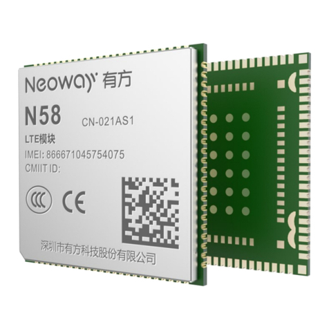
Neoway N1 CN User manual

N1_Hardware_User_Guide
Copyright © Neoway Technology Co., Ltd
i
N1Hardware User Guide
Version 1.6

N1_Hardware_User_Guide
Copyright © Neoway Technology Co., Ltd
i
Copyright © 2017 Neoway Technology Co., LtdAll right is reserved
is the trademark of Neoway Technology Co., Ltd.
All other trademarks and trade names mentioned in this document are the property of their respective
holders.
Remarks
This document is intended for system engineers (SEs), development engineers, and test engineers.
The information in this document is subject to change without notice due to product version update
or other reasons.
Every effort has been made in preparation of this document to ensure accuracy of the contents, but all
statements, information, and recommendations in this document do not constitute a warranty of any
kind, express or implied.
Neoway provides customers complete technical support. If you have any question, please contact
your account manager or email to
Sales@neoway.com
Support@neoway.com
Website: http://www.neoway.com

N1_Hardware_User_Guide
Copyright © Neoway Technology Co., Ltd
ii
Contents
About This Document ......................................................................................................... 1
1 Introduction to N1............................................................................................................. 1
1.1 Overview ............................................................................................................................................ 1
1.2 Block Diagram ................................................................................................................................... 2
1.3 Features .............................................................................................................................................. 2
2 Pin Description and PCB Foot Print .............................................................................. 6
2.1 Specifications and Pin Definition ....................................................................................................... 6
2.2 Pin Description ................................................................................................................................... 7
2.3 GPIOReference Level ...................................................................................................................... 15
2.4 PCBFoot Print .................................................................................................................................. 16
3 Power Supply Interfaces ................................................................................................ 17
3.1 Power Supply ................................................................................................................................... 17
3.2 Power-On.......................................................................................................................................... 20
3.3 Hard Reset ........................................................................................................................................ 21
3.4 Hard Power-off................................................................................................................................. 22
3.5 VRTC Power Supply ........................................................................................................................ 22
3.6 Battery Management ........................................................................................................................ 23
4 Video I/O Interfaces........................................................................................................ 25
4.1 LCD Interfaces ................................................................................................................................. 25
4.1.1 WVGA .................................................................................................................................... 25
4.1.2 720P ........................................................................................................................................ 28
4.2 TP Interfaces..................................................................................................................................... 29
4.3 Camera Interfaces............................................................................................................................. 30
4.3.1 Main Camera ........................................................................................................................... 30
4.3.2 Sub-Camera............................................................................................................................. 32
4.3.3 Design Precautions.................................................................................................................. 33
4.3.4 Camera Power Supply............................................................................................................. 35
4.4 Design Precautions ........................................................................................................................... 35
5 Audio Interface ................................................................................................................ 37
5.1 Audio Input....................................................................................................................................... 37
5.2 Audio Output .................................................................................................................................... 37
5.3 Headphone Interfaces ....................................................................................................................... 38
5.4 Audio Design Precautions ................................................................................................................ 40
6 Peripheral Interfaces....................................................................................................... 41

N1_Hardware_User_Guide
Copyright © Neoway Technology Co., Ltd
iii
6.1 USB Interface ................................................................................................................................... 41
6.2 UIM Card Interface .......................................................................................................................... 42
6.3 SDIO................................................................................................................................................. 43
6.3.1 SD Card................................................................................................................................... 43
6.3.2 SD Peripheral Interface ........................................................................................................... 44
6.4 GPIO................................................................................................................................................. 44
6.4.1 UART ...................................................................................................................................... 45
6.4.2 I2C........................................................................................................................................... 46
6.4.3 SPI........................................................................................................................................... 46
6.5 ADC.................................................................................................................................................. 46
6.6 Other Interfaces ................................................................................................................................ 47
7 RF Interface....................................................................................................................... 48
7.1 2G/3G RF Design and PCB Layout ................................................................................................. 48
7.2 Wi-Fi/BT RF Design and PCB Layout ............................................................................................. 49
7.3 GPS RF Design and PCB Layout ..................................................................................................... 51
7.3.1 GPS Impedance ....................................................................................................................... 51
7.3.2 Active GPS Antenna Design.................................................................................................... 51
7.3.3 Passive GPS Antenna Design Reference ................................................................................. 52
7.4 FM RF Design and PCB Layout....................................................................................................... 53
8 Commissioning Interfaces............................................................................................. 55
8.1 FORCE_USB_BOOT....................................................................................................................... 55
9 Electrical Feature and Reliability ................................................................................. 56
9.1 Electrical Feature.............................................................................................................................. 56
9.2 Temperature...................................................................................................................................... 56
9.3 ESD Protection ................................................................................................................................. 56
10 RF Feature ....................................................................................................................... 58
10.1 Work Band...................................................................................................................................... 58
10.2 TX Power and RX Sensitivity ........................................................................................................ 59
11 Mounting and Packaging............................................................................................. 61
11.1 Mounting the Module onto the Application Board ......................................................................... 61
11.2 Packaging ....................................................................................................................................... 61
12 Abbreviations................................................................................................................. 62

N1_Hardware_User_Guide
Copyright © Neoway Technology Co., Ltd
iv
Table of Figures
Figure 1-1 N1 block diagram .................................................................................................................. 2
Figure 2-1 Top view of N1 ...................................................................................................................... 6
Figure 2-2 PCC foot print recommended for N1 .................................................................................. 16
Figure 3-1 Capacitors used for the power supply.................................................................................. 17
Figure 3-2 Reference design of power supply control .......................................................................... 18
Figure 3-3 Reference design of power supply controlled by p-MOSFET............................................. 18
Figure 3-4 Reference designs of separated power supply ..................................................................... 19
Figure 3-5 Push switch control ............................................................................................................. 20
Figure 3-6 MCU control........................................................................................................................ 20
Figure 3-7 N1power-on sequence ......................................................................................................... 20
Figure 3-8 Reset controlled by button................................................................................................... 21
Figure 3-9 Reset circuit with triode separating ..................................................................................... 21
Figure 3-10 N1reset sequence ............................................................................................................... 21
Figure 3-11 N1power-off sequence....................................................................................................... 22
Figure 3-12 VRTC design in the module .............................................................................................. 22
Figure 3-13 Battery connections ........................................................................................................... 24
Figure 4-1 Reference MIPI circuits with common mode chokes .......................................................... 26
Figure 4-2 N1LCD backlight chipset .................................................................................................... 27
Figure 4-3 Power supply of N1LCD driver........................................................................................... 27
Figure 4-4 Reference design of LCD interface ..................................................................................... 28
Figure 4-5 Reference design of TP interface......................................................................................... 30
Figure 4-6 Reference design of the main camera interface ................................................................... 32
Figure 4-7 Reference design of sub-camera interface ........................................................................... 33
Figure 4-8 Scan direction of 3264*2448 LCD ...................................................................................... 33
Figure 4-9 Reference design of customized camera.............................................................................. 34
Figure 4-10 Adjustment of camera sensor............................................................................................. 34
Figure 4-11 Reference design of the main camera power supply ......................................................... 35
Figure 4-12 Reference design of the main camera power supply ......................................................... 35
Figure 5-1 Reference design of MIC connection .................................................................................. 37
Figure 5-2 Reference design of EAR/SPK connections........................................................................ 38
Figure 5-3 Reference design of headphone without FM ....................................................................... 39

N1_Hardware_User_Guide
Copyright © Neoway Technology Co., Ltd
v
Figure 5-4 Headphone interface............................................................................................................ 39
Figure 6-1 USB circuit(without OTG) .................................................................................................. 41
Figure 6-2 USB circuit (with OTG) ...................................................................................................... 42
Figure 6-3 Reference design of SIM card interface .............................................................................. 42
Figure 6-4 Reference design of TF card interface................................................................................. 43
Figure 6-5 Reference design of the UART interface ............................................................................. 45
Figure 6-6 Reference design of I2C ...................................................................................................... 46
Figure 6-7 Reference design of the SPI................................................................................................. 46
Figure 6-8 Reference design of motor circuit ....................................................................................... 47
Figure 7-1 Reference of antenna matching design ................................................................................ 48
Figure 7-2 Recommended RF PCB design ........................................................................................... 48
Figure 7-3 Encapsulation specifications of Murata RF connector ........................................................ 49
Figure 7-4 RF connections .................................................................................................................... 49
Figure 7-5 Antenna layout..................................................................................................................... 50
Figure 7-6 Clearance around the antenna.............................................................................................. 50
Figure 7-7 GPS RF structure................................................................................................................. 51
Figure 7-8 Power supply reference for active antenna .......................................................................... 52
Figure 7-9 Passive GPS antenna design reference ................................................................................ 53
Figure 7-10 Reference design of the headphone circuit with FM function ........................................... 54
Figure 8-1 Reference design of the fastboot interface........................................................................... 55

N1_Hardware_User_Guide
Copyright © Neoway Technology Co., Ltd
vi
Table of Tables
Table 1-1 N1 baseband and wireless features ......................................................................................... 2
Table 2-1 N1 dimensions ........................................................................................................................ 6
Table 2-2 N1 pin description................................................................................................................... 7
Table 4-1 WVGA LCD pin description ................................................................................................ 25
Table 4-2 720P LCD pin description..................................................................................................... 28
Table 4-3 TP pins .................................................................................................................................. 29
Table 4-4 Main camera pins.................................................................................................................. 31
Table 4-5 Sub-camera pins.................................................................................................................... 32
Table 5-1 Audio input pins.................................................................................................................... 37
Table 5-2 Audio output pins.................................................................................................................. 38
Table 5-3 Headphone pins .................................................................................................................... 38
Table 6-1 TF card pins .......................................................................................................................... 43
Table 6-2 GPIO pins ............................................................................................................................. 44
Table 6-3 ADC pin................................................................................................................................ 47
Table 8-1 Fastboot pins (en) ................................................................................................................. 55
Table 9-1 N1electricalfeature................................................................................................................ 56
Table 9-2 Temperature feature .............................................................................................................. 56
Table 9-3 N1 ESD feature..................................................................................................................... 57
Table 10-1 N1RF work band................................................................................................................. 58
Table 10-2 N1 WIFI/BT 2.4Gwork parameters .................................................................................... 58
Table 10-3 N1 GNSSwork parameters.................................................................................................. 59
Table 10-4 N1 RF power and RX sensitivity ........................................................................................ 59

N1_Hardware_User_Guide
Copyright © Neoway Technology Co., Ltd
vii
Revision Record
Version
Changes
Revised By
Date
V1.0
Initial draft
Tian
2016-01
V1.1
Added interface design
Tian
2016-06
V1.2
Modified the reflow temperature
Li
2016-07
V1.3
Modified the description of battery design
Modified the parameters of power supply driver
Supplemented reference level
Li
2016-08
V1.4
Added EU and NA frequency bands
Li,Qin
2016-09
V1.5
Added temperature range for limit work
Added work description of WIFI,BT,GPS
Added caution for some pin
Qin
2017-06
V1.6
Modified operating temperature range
Shen
2017-09

N1_Hardware_User_Guide
Copyright © Neoway Technology Co., Ltd
1
About This Document
This documentdetails the features, indicators, and reference standards of the N1 module and provides the
pin list and description. This user guide can help developers to complete wireless communication product
development on N1 easy.
1 Introduction to N1
1.1 Overview
N1is an industrial grade smart module that is developed on Qualcomm platform and supports Android OS
and windows 10. Its dimensions are 40mm x 40 mm x 2.8mm. It is well applicable to in-vehicle
computers, multimedia terminals, smart homes, IoT terminals, etc, with the following features:
Quad-core ARM Cortex-A7 processors, 1.3 GHz main frequency, 512KB L2 cache, 28 nm
8Gb LPDDR2 RAM; 8GB Nand Flash expandable up to 32 GB, eMMC interface,
GSM/WCDMA/HSPA+ (42 Mbps), CDMA2000/EV-DOrA, LTE Cat 4, WiFi 802.11b/g/n, BT4.0,
GPS/GLONASS/BEIDOU communications modes; FM radio
Android 5.1 OS
LCDdisplay with MIPI DSI interface, supporting at most 720*1280
MIPI dual-camera, among which the main camera supports at most 8MP, and the sub camera can
support at most 3MP
Multiple-channel audio I/O, supporting stereo headphone
USB2.0 high-speed serial port, SDIO3.0, 10-bit ADC, UART, SPI, I2C, PWM, GPIO, charging
management, etc.
N1 series include the following models:
Band
Model
LTE
B1
B2
B3
B4
B5
B7
B8
B17
B19
B20
B38
B39
B40
B41
N1_CN
●
●
●
●
●
●
N1_EU
●
●
●
●
●
N1_NA
●
●
●
●
●
Band
Model
UMTS
CDMA
TD-SCDMA
GSM
B1
B2
B4
B5
B8
BC0
B34
B39
850
900
1800
1900
N1_CN
●
●
●
●
●
●
●
●
●
N1_EU
●
●
●
●
●
●
N1_NA
●
●
●
●
●
●
●
●

N1_Hardware_User_Guide
Copyright © Neoway Technology Co., Ltd
2
CN: China EU: Europe NA: North America
1.2 Block Diagram
Figure 1-1 shows the block diagram of N1.
Figure 1-1 N1 block diagram
Power Management
RF Section
LCD
(MIPI)
TP
(MIPI)
Main/Sub
Cam
(MIPI)
USB/UART/SPI/I2C/GPIO/
PWM
Power
supply
input
Memory Baseband
4G
DRX
GPS
Audio
2G/3G
/4G
BT /
Wi-Fi
ADC
Charge
Analog
interface
Digital interface
1.3 Features
Table 1-1 N1 baseband and wireless features
Specifications
Description
Power supply
VBAT: 3.5V to 4.2V, typical value 3.9V
Current
Flight mode: 2 mA
Sleeping mode: 4mA
Recommended
-35°C to +75°C

N1_Hardware_User_Guide
Copyright © Neoway Technology Co., Ltd
3
operating temperature
Extended operating
temperature
-40°C to -35°C and +75°C to +85°C
Baseband temperature
Processor
Quad-core ARM Cortex-A7 processor
Main frequency: 1.3 GHz
512KBL2 cache
Memory
8Gb LPDDR2 SDRAM (495 MB is available)
32-bit bus
Maximum operation frequency 533MHz
Storage
8GB NAND Flash (4.66 GB is available)
Embedded EMMC
Expandable up to 32 GB
Multimedia processor
QDSP6 v5 core
Operation frequency 691 MHz
768KB L2
RF feature
Band
N1_CN:
GSM/GPRS/EDGE: 850M/900M/1800M/1900M
TD-SCDMA: B34/B39
CDMA2000 1x/EVDO: BC0
UMTS: B1/B8
FDD-LTE: B1/B3
TDD-LTE: B38/B39/B40/B41
N1_EU:
GSM/GPRS/EDGE: 850M/900M/1800M/1900M
UMTS: B1/B8
FDD-LTE: B1/B3/B7/B8/B20
N1_NA:
GSM/GPRS/EDGE: 850M/900M/1800M/1900M
UMTS: B2/B4/B5/B8
FDD-LTE: B2/B4/B5/B7/B17
Transmit power
GSM850/EGSM900:33±2 dBm (Power Class 4)
DCS1800/PCS1900:30±2 dBm (Power Class 1)
EDGE 850M/900MHz:27±3 dBm (Power Class E2)
EDGE1800MHz/1900MHz:26±3 dBm (Power Class E2)
WCDMA/HSPA:23+1/-3dBm (Power Class 3)
CDMA/EVDO:23+1/-3dBm(Power Class 3)

N1_Hardware_User_Guide
Copyright © Neoway Technology Co., Ltd
4
TD-SCDMA:23+1/-3dBm (Power Class 3)
LTE:23±2 dBm(Power Class 3)
Protocol
GSM/GPRS/EDGE
TD-SCDMA R8 1.28 TDD 4.2Mbps(DL), 2.2Mbps(UL)
WCDMA R99/R9 DC-HSDPA+ 42Mbps(DL), R6 HSUPA 11Mbps(UL)
CDMA2000@1x,1xAdvanced,1xEV-DOrA 3.1Mbps(DL),1.8Mbps(UL)
LTE Cat4 R9, Max.150Mbps(DL),50Mbps(UL)
Satellite positioning
GPS / BEIDOU/ GLONASS
Antenna feature
50Ω impedance
Multimedia
Display interface
4-lane MIPI_DSI, each of which supports 1.5 Gbps
Support WVGA (2-lane MIPI_DSI), at most 720qHD (4-lane MIPI_DSI)
24-bit color depth
Camera Interfaces
MIPI_CSI, at most 1.5 Gbps, supporting 2 cameras
Rear camera uses 2-lane MIPI_CSI, supporting at most 8MP
Front camera uses 1-lane MIPI_CSI, supporting at most 3MP
Video processing
Coding:
H.264 BP/MP –HD, 30 fps
MPEG-4 SP / H.263 P0 –WVGA, 30 fps
VP8 –WVGA, 30 fps
Decoding:
H.264 BP/MP/HP –RES, 30 fps
MPEG-4 SP/ASP –RES, 30 fps
DivX 4x/5x/6x –RES, 30 fps
H.263 P0 –WVGA, 30 fps
VP8 –RES, 30 fps
(HEVC) H.265 MP 8 bit –RES, 30 fps
Graphics processing
unit
Adreno 304, at most 400MHz 3D graphics processing, GMEM 96kB
API supports OpenGL ES 1.x, 2.0, 3.0/ DirectX 9.3
Audio
Encoder/decoder
Voice encoding/decoding supports G711, Raw PCM, QCELP; EVRC,
-B, -WB; AMR-NB, -WB; GSM-EFR, -FR, -HR
Audio encoding/decoding supports MP3; AAC, AAC+, eAAC;
AMR-NB, -WB, G.711, WMA 9/10 Pro
Noise rejection
Audio Input
2 groups of analog MIC input, embedding internal bias
Audio Output
Class-AB headphone amplifier
Class-AB differential receiver amplifier
Class-D speaker amplifier
Connection feature

N1_Hardware_User_Guide
Copyright © Neoway Technology Co., Ltd
5
UART
At most 4 Mbps, 2 groups
I2C
2 groups of I2C
SPI
1 group, supporting only host mode (two peripherals)
At most 52Mbps
UIM
2 groups, 1.8V/2.85V dual-voltage adaptive
USB
1 group of USB2.0 high-speed interface, a maximum transmitting rate of
480 Mbps
SDIO
Supporting SD3.0 and SD/MMC cards,4-bit SDIO
Wireless connection
WLAN
2.4G single band, supporting 802.11b/g/n, at most 150Mbps
Wake-on-WLAN (WoWLAN)
Ad-Hoc mode
WAPI supports SMS4 hardware encryption
AP mode
Wi-Fi Direct
Bluetooth
BT4.1LE or earlier versions
FM
Supporting Rx, 76 to 108MHz, channel spacing of 50 kHz
RDS (Europe), RBDS (USA)
Commissioning Interface
Fastboot mode
Forcibly enable USB control

N1_Hardware_User_Guide
Copyright © Neoway Technology Co., Ltd
6
2 Pin Description and PCB Foot Print
2.1 Specifications and Pin Definition
Table 2-1 N1 dimensions
Specifications
N1
Dimensions
(40±0.1)mm*(40±0.1)mm*(2.8±0.1)mm(H*W*D)
Weight
9.0g
Package
152-Pin LCC
Figure 2-1 Top view of N1
N1

N1 Smart Module Hardware User Guide
Copyright © Neoway Technology Co., Ltd
7
2.2 Pin Description
Table 2-2 N1 pin description
Pin
No.
Pin Name
General
Function
Level
Feature
Interrupt
GPIO
Alternate
Function 1
Alternate
Function 2
Alternate
Function 3
1
VIB_DRV_N
MOTOR
2,3
VBAT
VBAT
3.5~4.2V
4,5
VBUS_USB_IN
USB Power
5V
6
GND
GND
7
USB_DM
USB-
8
USB_DP
USB+
9
GND
GND
10
USB_HS_ID
USB
1.8V high
level by
default
11
GPIO_52
UIM2
1.8V
52
UIM2_PRESENT
12
UIM2_RESET
UIM2
13
UIM2_CLK
UIM2
14
UIM2_DATA
UIM2
15
VREG_UIM2
UIM Power
1.8V/2.85
V
16
GND
GND
17
GPIO_56
UIM1
1.8V
56
UIM1_PRESENT

N1 Smart Module Hardware User Guide
Copyright © Neoway Technology Co., Ltd
8
18
UIM1_RESET
UIM1
19
UIM1_CLK
UIM1
20
UIM1_DATA
UIM1
21
VREG_UIM1
UIM Power
1.8V/2.85
V
22
GND
GND
23
SDC2_DATA2
TF
24
SDC2_DATA3
TF
25
SDC2_CMD
TF
26
VREG_SDC_PWR
TF
2.95V
27
SDC2_CLK
TF
28
SDC2_DATA0
TF
29
SDC2_DATA1
TF
30
SD_CARD_DET_N
TF
1.8V
►
38
SD_CARD_DET_
N
CCI_TIMER2
31
GND
GND
32
GPIO_15
1.8V
15
BLSP4_SPI_CLK
BLSP4_I2C_SCL
33
GPIO_14
1.8V
14
BLSP4_SPI_CS_N
BLSP4_I2C_SDA
34
TS_INT_N
TP
1.8V
►
13
BLSP4_SPI_MISO
35
TS_RST_N
TP
1.8V
►
12
BLSP4_SPI_MOSI
36
WLED_PWM
LCD
4.2V
PM-MPP_2
37
LCD_DIF
LCD
1.8V
23
UIM3_CLK

N1 Smart Module Hardware User Guide
Copyright © Neoway Technology Co., Ltd
9
38
LCD_RST_N
LCD
1.8V
►
25
DSI_RST
MDP_VSYNC_S
39
LCD_TE
LCD
1.8V
24
MDP_VSYNC_P
40
GND
GND
41
MIPI_DSI0_LANE1_P
LCD
42
MIPI_DSI0_LANE1_M
LCD
43
MIPI_DSI0_CLK_M
LCD
44
MIPI_DSI0_CLK_P
LCD
45
MIPI_DSI0_LANE2_P
LCD
46
MIPI_DSI0_LANE2_M
LCD
47
MIPI_DSI0_LANE3_M
LCD
48
MIPI_DSI0_LANE3_P
LCD
49
MIPI_DSI0_LANE0_M
LCD
50
MIPI_DSI0_LANE0_P
LCD
51
GND
52
MIPI_CSI0_LANE0_P
REAR CAMEAR
53
MIPI_CSI0_LANE0_M
REAR CAMEAR
54
MIPI_CSI0_CLK_P
REAR CAMEAR
55
MIPI_CSI0_CLK_M
REAR CAMEAR
56
MIPI_CSI0_LANE1_P
REAR CAMEAR
57
MIPI_CSI0_LANE1_M
REAR CAMEAR

N1 Smart Module Hardware User Guide
Copyright © Neoway Technology Co., Ltd
10
58
GND
59
MIPI_CSI1_LANE0_M
FRONT
CAMERA
60
MIPI_CSI1_LANE0_P
FRONT
CAMERA
61
MIPI_CSI1_CLK_P
FRONT
CAMERA
62
MIPI_CSI1_CLK_M
FRONT
CAMERA
63
GND
64
CAM0_MCLK
REAR CAMEAR
26
CAM_MCLK0
GP_PDM_0B
65
CAM1_MCLK
FRONT
CAMERA
27
CAM_MCLK1
GP_PDM_1B
66
GND
67
ANT-WIFI/BT
ANT-WIFI/BT
68
GND
69
CAM0_RST_N
REAR
CAMEAR
1.8V
►
35
CAM1_RST_N
70
CAM0_PWDN
REAR CAMEAR
1.8V
►
34
CAM1_STANDB
Y_N
71
CAM1_PWDN
FRONT
CAMERA
1.8V
33
CCI_ASYNC0
72
CAM1_RST_N
FRONT
CAMERA
1.8V
►
28
WEBCAM_RST_
N
GP_PDM_2B

N1 Smart Module Hardware User Guide
Copyright © Neoway Technology Co., Ltd
11
73
CAM_I2C_SCL
CAMERA_I2C_S
CL
1.8V
30
BLSP3_I2C_SCL
74
CAM_I2C_SDA
CAMERA_I2C_S
DA
1.8V
29
BLSP3_I2C_SDA
75
GPIO_31
1.8V
►
31
CCI_TIMER0
GP_CLK0
76
CAM_FLASH_TORCH
_MODE
CAM_FLASH
1.8V
32
CCI_TIMER1
GP_CLK1
77
SENSORS_I2C_SCL
SENSORS_I2C_S
CL
1.8V
7
BLSP1_SPI_CLK
BLSP1_UART_RF
R_N
BLSP1_I2C_SCL
78
SENSORS_I2C_SDA
SENSORS_I2C_S
DA
1.8V
6
BLSP1_SPI_CS_N
BLSP1_UART_C
TS_N
BLSP1_I2C_SDA
79
UART1_MSM_RX
1.8V
►
5
BLSP1_SPI_MISO
BLSP1_UART_R
X
BLSP2_SPI_CS3
_N
80
UART1_MSM_TX
1.8V
4
BLSP1_SPI_MOSI
BLSP1_UART_T
X
BLSP3_SPI_CS3
_N
81
KEY_VOL_UP_N
KEY
1.8V
90
KYPD_SNS0
82
GPIO_93
1.8V
93
83
GND
84
ANT_TRX
ANT_TRX
85
GND
86
KEY_VOL_DOWN_N
KEY
1.8V
►
91
KYPD_SNS1
87
GPIO_92
1.8V
►
92
KYPD_SNS2
88
GPIO_88
1.8V
88
RFFE4_CLK
89
GPIO_89
1.8V
89
RFFE4_DATA

N1 Smart Module Hardware User Guide
Copyright © Neoway Technology Co., Ltd
12
90
GPIO_3
1.8V
3
GPIO_3
MI2S_2_D1
91
GPIO_2
1.8V
2
GPIO_2
MI2S_2_D0
92
GPIO_1
1.8V
1
GPIO_1
MI2S_2_SCK
93
GPIO_0
1.8V
0
GPIO_0
MI2S_2_WS
94
GPIO_98
1.8V
►
98
MI2S_2_MCLK
MI2S_1_MCLK_B
95
GPIO_69
1.8V
69
RFFE2_DATA
96
LED_SINK
1.8V
68
RFFE2_CLK
97
I2C_SCL
1.8V
►
112
BLSP2_SPI_CLK
BLSP2_UART_RF
R_N
BLSP2_I2C_SCL
98
I2C_SDA
1.8V
►
111
BLSP2_SPI_CS_N
BLSP2_UART_C
TS_N
BLSP2_I2C_SDA
99
UART2_MSM_RX
1.8V
21
UIM3_PRESENT
BLSP2_SPI_MISO
BLSP2_UART_R
X
100
UART2_MSM_TX
1.8V
20
UIM3_DATA
BLSP2_SPI_MOSI
BLSP2_UART_T
X
101
GPIO_97
1V8_EN
1.8V
►
97
HDSET_DET
BLSP1_SPI_CS1_
N
102
GPIO_110
1.8V
►
110
MI2S_1_WS_B
103
ALSP_INT_N
1.8V
►
94
ALSP_INT
MI2S_1_SCK_B
104
MAG_INT_N
1.8V
►
36
105
ACCL_INT2_N
1.8V
►
65
MAG_INT
BLSP3_SPI_CS2_
N
106
ACCL_INT1_N
1.8V
►
96
GYRO_ACCEL_I
NT_N
MI2S_1_D1_B
This manual suits for next models
2
Table of contents
Other Neoway Network Router manuals
