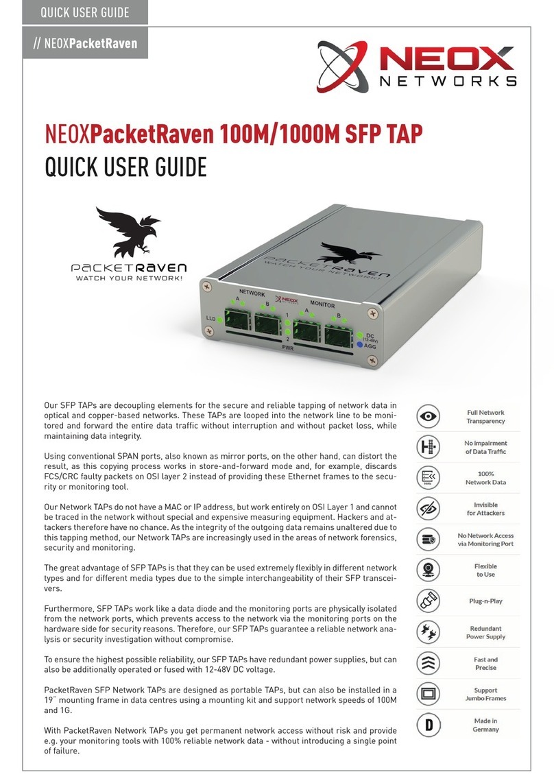
Neox PacketRaven PRP-SCC-1GA Series Instruction manual

// NEOXPacketRaven
QUICK USER GUIDE
Copper TAPs are active decoupling elements for the secure and reliable tapping of network
data in copper-based networks. These TAPs are looped into the copper line to be monitored
and transmit the entire data traffic without interruption.
Our Copper TAPs have redundant power supplies, which guarantees a high level of fail-sa-
fety. They do not have a MAC or IP address, but work on OSI Layer 1, and are therefore un-
detectable in the network without expensive measuring equipment.
Hackers and other attackers therefore have no chance and since the integrity of the trans-
mitted data remains unaltered due to this tapping method, Network TAPs are increasingly
used in the areas of network forensics, security and monitoring.
Using conventional SPAN ports, on the other hand, can distort the result because this tech-
nique works in store-and-forward mode and discards FCS/CRC errors at the OSI layer 2
level instead of outputting them on the mirror port. In contrast, TAPs pass out these critical
CRC errors without affecting the original data.
Furthermore, a Copper Network TAP works like a diode and does not allow access to the
network via the monitoring ports for security reasons. Professional network analysis is the-
refore only guaranteed through the use of TAPs.
PacketRaven Network TAPs are designed as portable TAPs, but can also be installed in data
centres via a mounting kit in a 19“ mounting frame and support network speeds of 10M,
100M and 1G.
With PacketRaven Copper TAPs you get permanent network access without risk and provide
e.g. your monitoring tools with 100% reliable network data without introducing a single point
of failure.
NEOXPacketRaven 10/100/1000Base-T Copper TAPs
QUICK USER GUIDE

// NEOXPacketRaven
QUICK USER GUIDE
Unidirectional network devices are typically used to provide
information security or protection of critical digital systems,
such as industrial control systems or production networks
from cyber-attacks.
Our TAPs work like a diode and, for security reasons, do not
allow access to the network via the monitoring ports.
By adding this further security layer, it is thus not possible to
compromise the network connection and the productive net-
work.
2. Data Diode Function
Data diodes guarantee unidirectional communication and ensure that data traffic can only flow in one direc-
tion.
3. PoE - Power over Ethernet Functions
The TAP supports both passive PoE and active PoE for passing through the power
supply to a PoE-capable device:
• PoE/PoE+ pass-through according to IEEE802.af - the maximum power con-
sumption that an end device can draw via the TAP is 12.95W
• Power supply of the TAP via PoE according to IEEE802.af (active/passive)
To connect the TAP to a PoE port according to IEEE802.af, please follow the installation steps below:
Firstconnectthe TAP tothe PSE (Power Sourcing Equipment) device and make surethat the PoE+ LED lights up.
As soon as this lights up, the PSE and the TAP have negotiated the power supply and you can now connect
your PoE end device to the TAP.
This sequence must be followed so that the TAP can properly establish power supply via a PSE device per
IEEE802.af.
All other power supply inputs on the TAP can still be used; the PoE power supply increases the redundancy
in this case.
3.1 TAP Power Supply via PoE
1. More Highlights
• Plug-n-Play, no complex configuration necessary
• Data diode function, does not allow access to the network via the monitoring ports
• Our portable Network TAPs support MDI/MDIX auto-determination.
• This means you can use both straight-through/patch cables and crossover cables.
• Support for 16k Jumbo Frames
• Support for PoE/PoE+ IEEE802.3af passthrough and power supply via PoE IEEE802.3af
• Mirrors 100% of the data traffic including FCS/CRC erroneous packets that may be discarded by SPANs
• Can be powered by redundant AC/DC power supplies (5V)
• Designed, assembled, certified and tested in Germany

// NEOXPacketRaven
QUICK USER GUIDE
Depending on the configuration of the TAP speed (see section 6.3) the LEDs light up in different combinations.
It must be ensured that all devices connected to the NETWORK port are set to the same network speed when
configuring the TAP speed.
This is the only way to ensure smooth and transparent operation of the TAP. As soon as the TAP displays the
desired or configured link speed via the LEDs, proper operation of the TAP is ensured.
4.1 Front View - Meaning of the LEDs
(C) RJ45 Network Port and Status LEDs (see section 4.1)
(D) 2 Power LEDs for AC/DC 5V (see section 5.)
It is possible to connect up to 2 power supply units to ensure power supply redundancy.
(E) RJ45 Monitoring Port and Status LEDs (see section 4.1)
(F) DC Power LED for 12-48V DC (see section 5.)
If power is supplied via the 12-48V DC connection, this LED lights up.
(G) Aggregation Mode LED (see section 6.2)
If the Aggregation mode is activated instead of the standard Breakout mode, this LED lights up.
(A) Power over Ethernet (PoE+) LED
If PoE voltage is fed in via the connected net
work device, this LED lights up.
(B) Link Loss Detection (LLD) LED (see section 4.1):
LLD detects a non-existent link on one of its net
work ports and then shuts down the other net
work port.
This state is indicated by the LLD LED lighting
up.
4. Front View - Ports and LEDs
For reasons of compatibility and EMC protection, our TAPS may only be operated with the supplied power
supplies certified together with the TAP. If the TAP is nevertheless operated with power supplies other
than those supplied, any warranty claim granted for the TAP will be voided!
(A) DIP switch for LLD on/off, TAP mode and speed
(see section 6.)
(B) Connection for 12-48V DC voltage.
The polarity at the DC connection does not matter, as the TAP
automatically detects the live line and passes the power supply
to the TAP accordingly in the required form!
(C) Redundant connections for AC/DC power supplies (5V)
5. Back View
NETWORK and MONITOR Port
=10M
NETWORK and MONITOR Port
= 100M
NETWORK and MONITOR Port
= 1G

// NEOXPacketRaven
QUICK USER GUIDE
6.1 Link Loss Detection (LLD)
Link Loss Detection is a function that checks whether the link has failed on either network port A or network
port B. If the link has failed on network port A when LLD is activated, the TAP also shuts down the link on
network port B, and vice versa. When the LLD function is selected (switch 1), the configuration is as follows:
• Activate LLD: Switch value 1• Deactivate LLD: Switch value 0
6.2 Operating Mode Configuration (may not be modifiable in the case of fixed pre-configured models!)
When selecting the operating mode (switches 2 & 3), the configuration is as follows:
The desired configuration should be set before plugging in the mains cable.
If an invalid configuration has been selected, all LEDs on the unit light up and the relay switches will not be
activated. In this case, switch off the unit and check the DIP switches.
When changing the configuration via DIP switches, it is always necessary to perform a restart by disconnecting
the power supply so that the new settings are activated!
• Breakout: Each Ethernet packet transmitted via the network line is mirrored separately in
this mode while maintaining data integrity in the TAP. The send and receive directions are
output separately on the two monitoring ports so that the network traffic can be analysed per
data direction in this case. Another great advantage of the Breakout mode is the visibility of
the network traffic even with a fully loaded network connection. In this mode, the set network
speed is transferred to the monitoring ports.
For example, if the TAP is configured for 100Base-T, then both monitoring ports will also com-
municate on 100Base-T accordingly. Switch value 00
• Aggregation: In this mode, the data streams are bundled and output aggregated on both of
the monitoring ports. This allows you to evaluate the network data of a full duplex line simul-
taneously with a single network interface on your analyzer. Due to the aggregation in hard-
ware (FPGA), faulty packet sequences during recording are a thing of the past in this mode.
For example, you can analyse the entire data traffic aggregated in 100Base-Tx lines without
loss.
The monitoring ports will always boot the link with 1000Base-TX, no matter what is negotiated
on the network side. Switch value 01
• Regeneration: Regeneration is used to capture 100% full duplex traffic that can be sent to
multiple monitoring devices (up to 3 in this case) for analysis of your network. In this mode, the
network speed settings are synchronised as in Breakout mode and the setting on the DIP switch
is applied to all ports. Switch value 10
As shown in the illustration on the left, the first
switch is used as the LLD on/off switch, the se-
cond and third are used to select the operating mode,
and the fourth and fifth are used to select the speed.
The switches numbered 6, 7 and 8 are ignored and left for
future use.
6. Configuration via DIP switch
Fail-Safe Mode: Since Network TAPs are usually installed in critical network lines, it must be ensured that
TAPs do not affect the line in any way.
By means of fail-safe, the TAP behaves like a cable bridge in the event of a failure or arbitrary deactivation
and ensures that the active network connection is not interrupted or at least continues to function without
the TAP function and thus does not negatively affect the active line.

// NEOXPacketRaven
QUICK USER GUIDE
ITEM NO. TAPS & ACCESSORIES
PRP-SCC-1GA*** 10/100/1000Base-T Copper TAP
PRP-SCC-1GB*** 10/100/1000Base-T Copper TAP - Breakout-only*
PRP-SCC-1GAO*** 10/100/1000Base-T Copper TAP - Aggregation-only**
PRP-1U3 Server rack mounting frame for portable 3 TAPs
PRP-1U3-BP Blank plate for mounting frame PRP-1U3
TAP
Dimensions: 10.60 cm x 3.50 cm x 16.40 cm
Weight: 460g
Consumption: max. 3 Watt at 5V/0.6A
Storage temperature: -40° to 70°C
Operating temperature: 0° to 55°C
Certifications: CE, FCC, RoHS, WEEE, EN55032 KL. A/B, EN55035,
EN61000-3-2, EN61000-3-3, EN61000-6-2
Power Supply
Input voltage: 110V-240V AC 50-60Hz
Output voltage: 5V DC
Output current: 2A
Power: max. 10 Watt
Power plug: with interchangeable plug head
5V Cable with ferrite ring
5V Connector - Screwable hollow plug
- 5.5 mm outer diameter
- 2.1 mm inner diameter
ITEM NO. POWER SUPPLIES & ACCESSORIES
PRP-PS-EU Power supply unit with EU plug (head)
PRP-PS-UK Power supply unit with UK plug (head)
PRP-PS-US Power supply unit with US plug (head)
PRP-PS-INT PSU with EU, UK, and US plug head
PRP-PS-*-A Plug head *EU, *UK or *US
PRP-SCC-1GB
PRP-1U3
PRP-1U3-BP
PRP-SCC-1GA
8. Item Numbers - TAPs & Accessories
7. Technical Specifications
* Breakout mode only available
10Base-T (10Mbit):
Switch value 00
100Base-TX (100Mbit):
Switch value 01
1000Base-T (1Gbit):
Switch value 10
The following constellation results for the speed selection (switches 4 & 5):
6.3 Speed Configuration
PRP-PS-INT
Breakout Mode Aggregation Mode Fail-Safe Mode
Regeneration Mode
** Aggregation mode only available
*** „-SEC“ for an IEC62443 Hardened TAP
and/or „-ERW“ for a TAP with mounting kit frame

NEOX NETWORKS GmbH
Monzastr. 4 · 63225 Langen · Germany
+49 6103 / 37 215 910 · solutions@neox-networks.com · www.neox-networks.com
// NEOXPacketSolutions
PRODUCT OVERVIEW
Portable & Compact NETWORK FORENSICS Appliances
High-End NETWORK PACKET BROKER for up to 400G
Modular & Scalable NETWORK FORENSICS Solution
Cost Efficient Next-Gen NETWORK PACKET BROKER
as Appliance or Virtual
Modular, Portable and Virtual NETWORK TAPS for up to 400G
Advanced PACKET PROCESSING up to 400Gbps
This manual suits for next models
2
Table of contents
Other Neox Network Hardware manuals
Popular Network Hardware manuals by other brands

Dell EMC
Dell EMC PowerFlex Appliance owner's guide

ZyXEL Communications
ZyXEL Communications WAP6405 quick start guide

Comtrol
Comtrol InterChangeVS1000 Installation and configuration guide
D-Link
D-Link ShareCenter Quattro DNS-345 Quick installation guide
Delta Electronics
Delta Electronics Network Device VFD unpacking instructions
ADC
ADC H4TU-C-388-L1 user manual

Bosch
Bosch VideoJet X10 Installation and operation manual

Cisco MERAKI
Cisco MERAKI MX450 installation guide
LEGRAND
LEGRAND Wattstopper 225CWS quick start guide

ADTRAN
ADTRAN T400 Installation and Maintenance

Cisco
Cisco Cisco ONS 15600 SDH troubleshooting guide
Huawei
Huawei FusionModule5000 Maintenance Guide
