Neptronic SKVF Series Manual

SKVF-ESL-211022
Evaporative Cooler
SKVF Series
Installation Instructions and User Manual
READ AND SAVE THESE INSTRUCTIONS
4011008

SKVF Evaporative Cooler
Installation Instructions and User Manual
www.neptronic.com
Page | 1
Foreword
Neptronic Company Overview
Founded in 1976, we’re a private corporation that designs, manufactures and distributes products for the HVAC industry.
Our product line includes intelligent controllers, electronic actuators, actuated valves, humidifiers and electric heaters.
Our products are designed and manufactured by over 250 dedicated employees in our 7,500 m2(80,000 ft2) state-of-the-
art facility located in Montreal, Canada. Using a vertical integration model, our entire manufacturing chain is under one
roof from software and hardware development to SMT circuit board assembly, to sheet metal fabrication, to product testing
ensuring that our products are engineered to last.
We currently hold several national and international patents and with our continued commitment to research and
development, we provide innovative products and technologies for the ever-evolving challenges of the HVAC industry.
Exporting over 75% of our sales, we have an exclusive distribution network around the globe that provides comprehensive
solutions to our worldwide customers.
About the Manual
These installation and operation instructions have been developed to facilitate the installation of the SKVF evaporative
cooler.
•The strict application of these instructions will ensure conformity of your installation and operation as per the
manufacturer's recommendations.
•The application of these instructions is one of the conditions for the application of the warranty.
•The application of these instructions does not ensure, at any time conformity to procedures, regulation or local
codes, regarding electric installation and connection to local water supply.
This product has been declared to conform to the applicable Canadian and American safety standards and directives and
bear the ETL (c) & (us) mark. The Certificate of Conformity for ETL is available, upon request with the manufacturer.
This product has been declared to conform to applicable European safety and electromagnetic compatibility standards
and directives and bear the CE mark. The certificate of conformity CE is available upon request to the manufacturer.
2021©: All rights reserved. This document cannot be reproduced totally or partially by any means whether, electronic,
mechanical, photocopy, recording or other, without prior written authorization of Neptronic.
General Warranty
This product is subject to the terms and conditions described at www.neptronic.com/Sales-Conditions.aspx

SKVF Evaporative Cooler
Installation Instructions and User Manual
www.neptronic.com
Page | 2
Health and Safety Instructions
General
This manual has been written to ensure correct, safe and sustainable operation of the SKVF evaporative cooler and is
intended for use by engineers and technical personnel trained by Neptronic or their official agents. This manual must be
read thoroughly before specifying, designing, installing or operating an SKVF. Please retain for reference and contact
Neptronic for any questions.
Electrical Warning Message
WARNING:
Risk of electric shock. Do not access. Disconnect the SKVF prior to opening the access door.
All work concerned with electrical installation MUST only be performed by skilled and qualified technical personnel such as
an electrician or a technician with appropriate training. The customer is always responsible for ensuring the suitability of
the technical personnel.
Please observe local regulations concerning the provision of electrical installations.
Health & Safety
Installation, maintenance, repair work or de-commissioning must only be carried out by appropriately qualified and
properly trained technical personnel. Any risks or hazards relating to the system, including during installation and
maintenance, must be identified by a competent Health & Safety representative who shall be responsible for introducing
effective control measures as necessary. The customer is responsible for ensuring that the installation of the equipment
complies with all local regulations.
CAUTION: Maintenance personnel must be trained by Neptronic or their official agent and it is the
customer’s responsibility to ensure their suitability. Failure to use properly trained personnel may lead
to a hazardous operating condition.
WARNING: Danger of electrocution! Danger of contact with live parts when the unit is open. Always
isolate all water and electrical supplies to the system before commencing any maintenance or repair.
Isolate power and water immediately if there are any sign of water leaking from the unit.
WARNING: This appliance is not intended for use by persons (including children) with reduced
physical, sensory or mental capabilities, or lack of experience and knowledge, unless they have been
given supervision or instruction concerning use of the appliance by a person responsible for their
safety. Children must be supervised to ensure that they do not play with the appliance.
Protective Equipment
Please refer to the Health and Safety Executive for recommendations with regard to Personal Protective Equipment and
for information on the Control of Substances Hazardous to Health COSHH.

SKVF Evaporative Cooler
Installation Instructions and User Manual
www.neptronic.com
Page | 3
Hygiene
IMPORTANT:
Refer to local Health and Safety regulation and codes on the control of Legionellosis in water systems. In the absence of
such, ASHREA guideline 12-2000 does provide recommendations.
If not adequately maintained, water systems can support the growth of micro-organisms including the bacterium that
causes Legionnaires’ disease.
The SKVF has been designed to reduce as much as possible any possible risk of legionellosis growth. Users also share
the responsibility in reducing the risk of legionellosis; users are required to:
•Conduct a risk assessment of the complete water system.
•Implement proper control of the water system.
•Connect to a clean and chlorinated water supply main.
•Avoid stagnant water.
•Avoid water temperatures that increase risk of Legionella growth.
•Clean and disinfect the system regularly, refer to service section of the present Installation Instructions and User
Manual.
WARNING: Risk of Legionnaires’ disease which can be fatal. The SKVF evaporative cooler must be
installed, operated and serviced in accordance with this Installation Instructions and User Manual.
WARNING: In the event that the SKVF is turned off for prolonged periods (more than 24 hours),
ensure that any water storage tanks and pipe-work supplying the unit are drained, unless they
supply other systems which ensure a regular renewal of water in the system. Failure to do so may
result in stagnation of the water and contamination that might cause Legionnaires' disease, which
can be fatal.
It is the responsibility of the person on whom the statutory responsibility falls to determine all control and preventative
measures outlined in this manual.
Correct Use
Neptronic systems and its products are designed only for cooling and humidification use. Any other application is not
considered appropriate for the intended purpose. The manufacturer cannot be made liable for any damage resulting from
incorrect use.

SKVF Evaporative Cooler
Installation Instructions and User Manual
www.neptronic.com
Page | 4
Handling and Packaging
Handling
Always handle the SKVF evaporative cooler with care and keep within its original packaging for as long as possible, prior
to installation. It must be stored under cover and protected from any possible damage, from dust, rain or frost.
Correct Lifting Method
Lifting or handling must only be carried out by trained and qualified personnel. Ensure that the lifting operation has been
properly planned, risk assessed and that all equipment has been checked by a skilled and competent Health & Safety
representative and that effective control measures are put in place.
WARNING: It is the customer's responsibility to ensure that operators are trained in handling heavy
goods and to enforce the relevant lifting regulations.
WARNING: The SKVF must always be handled and lifted with care and remain in its original
packaging for as long as possible, prior to installation.
WARNING: The SKVF package may be carried using a forklift from the underside. Exercise caution
before lifting to ensure that the load is balanced.
Refer to dimensions and weights as indicated on page 9.
Inspection
Upon receipt, and once packaging material has been removed, an inspection must be carried out to ensure that no
damage occurred during transit. Any damage must be reported with no delay to your Neptronic representative.

SKVF Evaporative Cooler
Installation Instructions and User Manual
www.neptronic.com
Page | 5
Table of Contents
Overview.....................................................................................................................................................................6
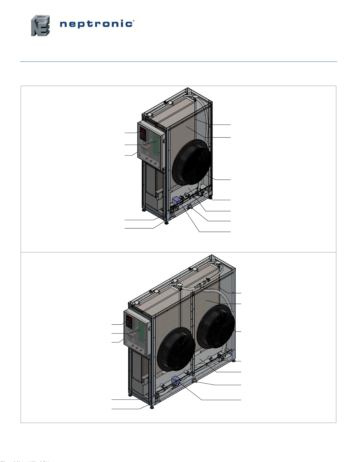
Visual Overview......................................................................................................................................................6
Nomenclature.........................................................................................................................................................7
Available Options....................................................................................................................................................7
Technical Specifications.........................................................................................................................................7
Output Specifications .............................................................................................................................................8
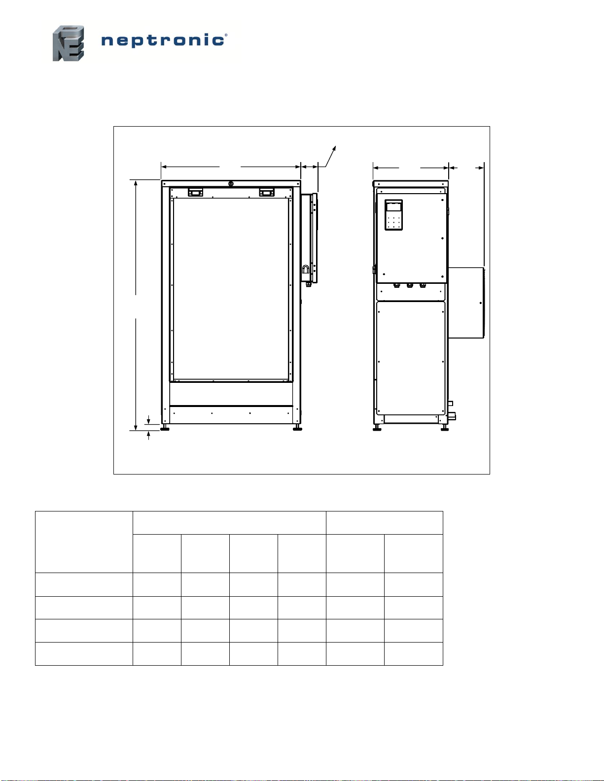
Dimensions and Weight .........................................................................................................................................9
Mechanical Installation.............................................................................................................................................11
General Recommendations..................................................................................................................................11
Floor Installation...................................................................................................................................................12
Ceiling Installation ................................................................................................................................................12
Air Filter Installation (Option)................................................................................................................................13
Plumbing Connections .............................................................................................................................................14
Water Quality Guide.............................................................................................................................................14
Reverse Osmosis Water ..................................................................................................................................14
Controlled Substances .....................................................................................................................................14
Water Monitoring..............................................................................................................................................14
Water Supply Installation......................................................................................................................................15
Water Drain Connections .....................................................................................................................................16
Electrical Connections..............................................................................................................................................17
Electrical Power Supply........................................................................................................................................17
Printed Circuit Board ............................................................................................................................................18
Safety Contacts................................................................................................................................................19
Dry Contacts.....................................................................................................................................................19
ON/OFF Control ...............................................................................................................................................20
Modulating Control ...........................................................................................................................................21
Network Communication ..................................................................................................................................23
HRL24 Control..................................................................................................................................................24
Controller Configuration ...........................................................................................................................................25
Controller Features...............................................................................................................................................25
Menu - General.................................................................................................................................................28
Menu - User Settings........................................................................................................................................31
Menu - Service .................................................................................................................................................33
Menu - Installation............................................................................................................................................34
Menu - Integration ............................................................................................................................................39
List of Alarms........................................................................................................................................................42
Start-up Procedure...................................................................................................................................................43
Servicing and Maintenance......................................................................................................................................45
Preventative Maintenance....................................................................................................................................45
Water Sampling and Testing (Hygiene) ...............................................................................................................46
Removing the Evaporative Media ........................................................................................................................47
Disinfection...........................................................................................................................................................48
De-scaling.............................................................................................................................................................49
Air Filter Maintenance ..........................................................................................................................................50
PCB Fuse Replacement.......................................................................................................................................51
Troubleshooting........................................................................................................................................................52

SKVF Evaporative Cooler
Installation Instructions and User Manual
www.neptronic.com
Page | 6
Overview
Visual Overview
ECM fan
Control panel
Stainless steel 304L
media cassette
Evaporative media
Circulation pump
(Only on SKVF-R models)
Drain valve
(Only on SKVF-R models)
Stainless steel 304L tank
Pan drain connection
Main drain connection
Water supply connection
Controller
PCB
SKVF-x15 to x30 Models
ECM fans
Stainless steel 304L
media cassettes
Circulation pump
(Only on SKVF-R models)
Drain valve
(Only on SKVF-R models)
Stainless steel 304L tank
Pan drain connection
Main drain connection
Water supply connection
Controller
PCB
Control panel
Evaporative medias
SKVF-x60 Models
Illustration 1 - Overview of SKVF Evaporative Cooler

SKVF Evaporative Cooler
Installation Instructions and User Manual
www.neptronic.com
Page | 7
Nomenclature
SKVF
-
R
60
-
85
B
C
S
Type:
R= Recirculation
D= Direct Feed
CFM*:
15 = 1500 CFM
30 = 3000 CFM
60 = 6000 CFM
Evaporation Factor†:
85 = 85%
Fan Position:
B= Back
L= Left
R= Right
Voltage§:
A= 120Vac/1ph
B= 208Vac/1ph
C= 230-240Vac/1ph
Control Panel:
S= Standard
* 120Vac/1ph models operate at 80% of maximum capacity and therefore output 80% of the nominal CFM.
†Option of 65 or 75% evaporation factor is also available upon request to the factory.
§Only 230-240Vac/1ph models are available with CE certification.
Available Options
The following options are available when purchasing a SKVF evaporative cooler:
•Air filter
•Air deflector
•BACnet and Modbus network communication board
•Ethernet (IP) board
•5 microns pre-filter and silver ion dosing anti-bacterial cartridges
•UV light
Technical Specifications
Table 1 - Technical Specifications
Model
Frequency
(Hz)
Rated voltage
(V)
Rated power
(W)
Rated current
(A)
Max air flow
(CFM) [m3/h]
SKVF-x15
50/60
120
364
3.0
1250 (2124)
208
364
1.8
1500 (2549)
240
364
1.5
SKVF-x30
50/60
120
700
5.8
2500 (4248)
208
700
3.4
3000 (5097)
240
700
2.9
SKVF-x60
50/60
120
1300
10.8
5000 (8495)
208
1300
6.3
6000 (10194)
240
1300
5.4

SKVF Evaporative Cooler
Installation Instructions and User Manual
www.neptronic.com
Page | 8
Output Specifications
Table 2 - Output Specifications (120V models)
72°F (22°C)
Entering
temperature
Entering RH:
10%RH
20%RH
30%RH
40%RH
CFM
(m3/h)
Humidification
Cooling
Humidification
Cooling
Humidification
Cooling
Humidification
Cooling
lbs/h
(kg/h)
kBTU/h
(kW)
lbs/h
(kg/h)
kBTU/h
(kW)
lbs/h
(kg/h)
kBTU/h
(kW)
lbs/h
(kg/h)
kBTU/h
(kW)
1250
(2124)
26.5
(12)
28.2
(8.3)
22.7
(10.3)
24.1
(7.1)
19.3
(8.8)
20.4
(6)
15.9
(7.2)
16.8
(4.7)
2500
(4248)
52.9
(24)
56.3
(16.5)
45.3
(20.5)
48.2
(14.1)
38.5
(17.5)
40.9
(12)
31.8
(14.4)
33.8
(9.3)
5000
(8495)
104.9
(47.6)
112.6
(33)
90.6
(41.1)
96.3
(28.2)
77.1
(35)
81.8
(24)
63.6
(28.8)
67.4
(18.6)
Leaving condition:
78%RH
52°F
(11°C)
82%RH
54°F
(12°C)
85%RH
57°F
(14°C)
88%RH
60°F
(16°C)
85°F (29°C)
Entering
temperature
Entering RH:
10%RH
20%RH
30%RH
40%RH
CFM
(m3/h)
Humidification
Cooling
Humidification
Cooling
Humidification
Cooling
Humidification
Cooling
lbs/h
(kg/h)
kBTU/h
(kW)
lbs/h
(kg/h)
kBTU/h
(kW)
lbs/h
(kg/h)
kBTU/h
(kW)
lbs/h
(kg/h)
kBTU/h
(kW)
1250
(2124)
32.3
(14.7)
34.2
(10)
27.2
(12.3)
28.8
(8.4)
22.9
(10.4)
24.2
(7.1)
18.8
(8.5)
19.8
(5.8)
2500
(4248)
64.5
(29.3)
68.3
(20)
54.3
(24.6)
57.5
(16.9)
45.8
(20.8)
48.4
(14.2)
37.4
(17)
39.4
(11.5)
5000
(8495)
128.9
(58.5)
136.7
(40.1)
108.7
(49.3)
115
(33.7)
91.7
(41.6)
96.8
(28.4)
74.8
(33.9)
78.9
(23.1)
Leaving condition:
76%RH
60°F
(16°C)
80%RH
64°F
(18°C)
85%RH
67°F
(19°C)
87%RH
70°F
(21°C)
Note: Humidity output for high RH entering conditions may be less than the above values calculated
with an evaporation factor for air at 50%RH.
Table 3 - Output Specifications (208 to 240V models)
72°F (22°C)
Entering
temperature
Entering RH:
10%RH
20%RH
30%RH
40%RH
CFM
(m3/h)
Humidification
Cooling
Humidification
Cooling
Humidification
Cooling
Humidification
Cooling
lbs/h
(kg/h)
kBTU/h
(kW)
lbs/h
(kg/h)
kBTU/h
(kW)
lbs/h
(kg/h)
kBTU/h
(kW)
lbs/h
(kg/h)
kBTU/h
(kW)
1500
(2549)
31.8
(14.4)
33.8
(9.9)
27.2
(12.3)
28.9
(8.5)
23.1
(10.5)
24.5
(7.2)
19.1
(8.7)
20.2
(5.9)
3000
(5097)
63.5
(28.8)
67.6
(19.8)
54.4
(24.7)
57.8
(16.9)
46.2
(21)
49.1
(14.4)
38.2
(17.3)
40.5
(11.9)
6000
(10194)
125.9
(57.6)
135.1
(39.6)
108.7
(49.3)
115.5
(33.8)
92.5
(42)
98.1
(28.8)
76.3
(34.6)
80.9
(23.7)
Leaving condition:
78%RH
52°F
(11°C)
82%RH
54°F
(12°C)
85%RH
57°F
(14°C)
88%RH
60°F
(16°C)
85°F (29°C)
Entering
temperature
Entering RH:
10%RH
20%RH
30%RH
40%RH
CFM
(m3/h)
Humidification
Cooling
Humidification
Cooling
Humidification
Cooling
Humidification
Cooling
lbs/h
(kg/h)
kBTU/h
(kW)
lbs/h
(kg/h)
kBTU/h
(kW)
lbs/h
(kg/h)
kBTU/h
(kW)
lbs/h
(kg/h)
kBTU/h
(kW)
1500
(2549)
38.7
(17.6)
41
(12)
32.6
(14.8)
34.5
(10.1)
27.5
(12.5)
29
(8.5)
22.5
(10.2)
23.7
(6.9)
3000
(5097)
77.4
(44.6)
82
(24)
65.2
(29.6)
69
(20.2)
55
(24.9)
58.1
(17)
44.9
(20.4)
47.3
(13.9)
6000
(10194)
154.7
(70.2)
164
(48.1)
130.5
(59.2)
138
(40.4)
110
(49.9)
116.2
(34)
89.8
(40.7)
94.7
(27.8)
Leaving condition:
76%RH
60°F
(16°C)
80%RH
64°F
(18°C)
85%RH
67°F
(19°C)
87%RH
70°F
(21°C)
Note: Humidity output for high RH entering conditions may be less than the above values calculated
with an evaporation factor for air at 50%RH.

SKVF Evaporative Cooler
Installation Instructions and User Manual
www.neptronic.com
Page | 9
Dimensions and Weight
SKVF-x15 to x30 Models
A
B
1.2"
(30mm)
3.25" (83mm)
C D
Illustration 2 - Dimensions (SKVF-x15 to x30 Models)
Table 4 - Dimensions and Weight (SKVF-x15 to x30 Models)
Model
Dimensions (inch) [mm]
Weight (lb) [kg]
A
B
C
D
Empty
Full
SKVF-x15-xxB
27
(686)
48
(1219)
14.5
(368)
6.8
(173)
124
(56)
164
(74)
SKVF-x15-xxL
SKVF-x15-xxR
27
(686)
48
(1219)
23.8
(605)
6.8
(173)
132
(60)
172
(78)
SKVF-x30-xxB
27
(686)
48
(1219)
14.5
(368)
5
(127)
133
(60)
173
(79)
SKVF-x30-xxL
SKVF-x30-xxR
27
(686)
48
(1219)
30.8
(782)
5
(127)
152
(69)
191
(87)

SKVF Evaporative Cooler
Installation Instructions and User Manual
www.neptronic.com
Page | 10
SKVF-x60 Models
A
B
1.2"
(30 mm)
3.25" (83 mm)
CD
Illustration 3 - Dimensions (SKVF-x60 Models)
Table 5 - Dimensions and Weight (SKVF-x60 Models)
Model
Dimensions (inch) [mm]
Weight (lb) [kg]
A
B
C
D
Empty
Full
SKVF-x60-xxB
50.8
(1290)
48
(1219)
14.5
(368)
5
(127)
192
(87)
269
(125)

SKVF Evaporative Cooler
Installation Instructions and User Manual
www.neptronic.com
Page | 11
Mechanical Installation
General Recommendations
WARNING: Failure to observe manufacturer's installation recommendations will invalidate the
manufacturer’s warranty.
Installation must conform to Local and National Codes.
Location
Consider the following points before deciding the location for the SKVF evaporative cooler:
•Plan a location that is easy to access and permits an easy inspection and servicing of the SKVF.
•Do not install the SKVF where failure of the appliance could cause damage to the building structure or to other
expensive equipment.
•Ensure that the ambient temperature is less than 104°F (40°C).
•Construct the drainpipe in such a way that there is no water accumulation and stagnation.
Positioning
•Ensure that the humid airstream of the fan(s) is not located close to a surface on which condensation can easily
build-up.
•Ensure that the control panel, fan(s), evaporative media and plumbing connections are accessible in order to
permit servicing.
•Leave the following minimum clearances around the evaporative cooler:
•Front of the unit where the evaporative media is located: 14” (356 mm) minimum
(it is recommended to leave 24” (610 mm) of clearance when more frequent access is required for servicing)
•Control panel: 24” (610 mm) minimum from the control panel
Note: Above minimum clearances are indicated for inspection and servicing access.
14"
(356mm)
24"
(610mm)
Illustration 4 - Evaporative Cooler Positioning

SKVF Evaporative Cooler
Installation Instructions and User Manual
www.neptronic.com
Page | 12
Floor Installation
•The SKVF evaporative cooler is provided with adjustable feet in order to ensure a proper level when installed
directly on the floor.
•Ensure that the SKVF is installed at a level of +/-1° in all directions.
•Provide a level, solid foundation for the evaporative cooler and ensure that the floor beneath the evaporative
cooler is waterproof to withstand any water spillage during servicing or in the event of a problem.
Ceiling Installation
•The SKVF can be hung by the ceiling using an appropriate support platform (by others). Consult local codes and
regulations for minimum structural requirements for such platforms.
•Ensure to use platforms that allow for level adjustment in order to keep the SKVF at a level of +/-1° in all
directions.
•Ensure to unscrew the legs of the SKVF and keep the 4x 3/8”-16 screws.
•The SKVF must be attached to the platform by the use of 4x 3/8”-16 screws fixed at the designated locations on
the bottom of the unit, as per the image below.
•The screws must not be inserted into the SKVF at a depth of more than ¾” (20mm).
4x mounting holes with
-screws
Bottom View: Location of Mounting Holes
Illustration 5 - Ceiling Installation

SKVF Evaporative Cooler
Installation Instructions and User Manual
www.neptronic.com
Page | 13
Air Filter Installation (Option)
1. Using 14x stainless steel self-tapping #8-18 x ½” screws, secure the bottom bracket assembly onto the SKVF
media panel.
2. Slide the air filter into the bottom bracket assembly.
3. Using 4x stainless steel self-tapping #8-18 x ½” screws, secure the top bracket onto the SKVF media panel.
4. Using 2x stainless steel self-tapping #8-18 x ½” screws, secure the top bracket to the bottom bracket assembly.
Media panel
Bottom bracket
assembly
Air filter
Top bracket
4x SS self-tapping
screws (#8-18 x ½
2x SS self-tapping
screws (#8-18 x ½
14x SS self-tapping
screws (#8-18 x ½
Illustration 6 - Air Filter Installation

SKVF Evaporative Cooler
Installation Instructions and User Manual
www.neptronic.com
Page | 14
Plumbing Connections
Plumbing Installation must conform to Local and National Codes.
Any installation work must be carried out by suitably qualified personnel.
Water Quality Guide
For normal operation of the SKVF evaporative cooler, Neptronic recommends connecting the SKVF to a clean and potable
source of water supply. Reverse osmosis (RO) water may be used for areas using hard water in order to minimise scale
build-up.
Reverse Osmosis Water
For SKVF evaporative coolers using RO water, Neptronic recommends operating the system within the following
parameters:
SKVF Type
Conductivity
Type R: Recirculation pump
> 100 μS/cm at 68°F (20°C)
Type D: Direct feed
> 150 μS/cm at 68°F (20°C)
The use of tanks and reservoirs using RO water is only permitted as part of a properly managed and hygiene monitored
water system and must be included as part of a water system risk assessment.
Controlled Substances
The supply water of the SKVF must be free of any toxic, carcinogenic and flammable substances, in order to avoid
contamination of the air passing through the media.
Refer to the table below for a list of substances that must not be found in the SKVF system.
Acrylamide
Antimony
Arsenic
Benzene
Benzo(a)pyrene
Boron
Bromate
Cadmium
Chromium
Clostridium perfringens (including
spores)
Cyanide
1,2-dichloroethane
Epichlorohydrin
Fluoride
Lead
Mercury
Nickel
Pesticides
Polycyclic aromatic hydrocarbons
Selenium
Tetrachloroethene and Trichloroethene
Trihalomethanes
Vinyl chloride
Water Monitoring
The water supply of the SKVF evaporative cooler must be monitored for hygiene as part of the maintenance program.
Refer to the Servicing and Maintenance section for further guidance.

SKVF Evaporative Cooler
Installation Instructions and User Manual
www.neptronic.com
Page | 15
Water Supply Installation
Connect the evaporative cooler to a clean drinking water supply.
•The SKVF evaporative cooler is capable of operating with tap and reverse osmosis (RO).
•If the evaporative cooler is connected to hard water, it will result in scale build-up on the evaporative module
and will require frequent cleaning and replacement.
•If the supplied water is treated with reverse osmosis filtration, control the total dissolved solid contents in the
water, otherwise the water will react as a solvent agent resulting in rapid evaporation and media degradation.
•Water conductivity must be between 100 and 550 µS/cm at 68°F (20°C).
•For direct feed models, water conductivity must not be lower than 150 microS/cm at 68°F (20°C). If it is lower,
mix the treated water with tap water to achieve the recommended conductivity. Alternatively, install an SKVF
with recirculation (SKVF-R) and setup the dilution ratio accordingly by modifying the value of the DilutionRatio
setting located in the Installation menu (see page 34).
•It is recommended to install a standard water strainer in the water supply line.
•It is recommended to install a water hammer arrestor, in order to absorb hydraulic shock and minimize water
hammer when the fill valve closes.
Water Inlet Specifications
•Minimum water supply pressure: 25 psi (170 kPa)
•Maximum water supply pressure: 70 psi (480 kPa)
•Maximum water supply temperature: 68˚F (20˚C)
Water Supply Line Installation
•Connect a ½”NPT (DN15) water supply braided hose (by others) to the water supply connection.
•To facilitate servicing, a shut off valve (not supplied) must be installed in the water line, within 40”(1m) of the
evaporative cooler.
Models
Water Inlet Connection Size
SKVF
Ø1/2” NPT (DN15) connection
Water supply
connection
½NPT (DN15)
Illustration 7 - Water Supply Connection

SKVF Evaporative Cooler
Installation Instructions and User Manual
www.neptronic.com
Page | 16
Water Drain Connections
Any installation work must be carried out by suitably qualified personnel.
Risk of flooding. Never connect drains to a closed pipe work. Always install a tundish to provide a
suitable air gap.
Water Drain Specification
Model
Water Drain Outlets Connection Size
SKVF
Ø3/4”(DN20)
Water Drain Installation
•The water drain outlet connections must be connected to drain piping of sufficient size. It is recommended to use
Ø3/4”(DN20) or bigger standard copper hydraulic pipes.
•Ensure that the slope of the drain line is no less than 10°.
•The maximum equivalent pipe length of the main drain must not exceed 20ft (6m) between the drain outlet of the
evaporative cooler and the open drain. Otherwise, the drain pipe diameter must be increased to 1-1/2” (DN40).
•A minimum 1’’ (25mm) air gap must be kept between the connection of the SKVF drain pipes and the open drain
line, in order to prevent any backflow to the SKVF evaporative cooler.
•The SKVF drain pipes must not have a drain trap installed and must be piped to an open drain.
•The open drain pipe must have a minimum diameter of 1-1/2” (DN40).
•The main drain and pan drain must not be piped together or to other appliances.
Main drain
Ø3/4(DN20) Pan drain
Ø3/4(DN20)
Maximum 20ft (6m)
Minimum open drain
of Ø1 ½ " (DN40)
Illustration 8 - Water Drain Connections

SKVF Evaporative Cooler
Installation Instructions and User Manual
www.neptronic.com
Page | 17
Electrical Connections
All work concerned with electrical installation MUST only be performed by a qualified electrician
and must conform to the procedure, regulation and local codes.
WARNING: Risk of electric shock. Isolate all power supplies before installation and maintenance of
the SKVF Evaporative cooler.
•Use copper conductors only.
•All incoming power supplies must be externally fused for over current protection.
•The electrical supply must also be isolated for the purpose of emergency and servicing.
•The isolator must have a contact separation of at least 1/8” (3 mm).
•An external over current protection and disconnect circuit breaker must be installed on the supply, adjacent to the
unit.
•Ensure that the size of the wire conductors is appropriate for the maximum current supplied.
•Ensure that the incoming power cable is secured via a suitably sized cable gland.
•Ensure that each terminal connection is secured firmly with a cable ferrule.
•The SKVF evaporative cooler cabinet has an uninterrupted or unbroken electrical ground. Do not use the unit’s
frame to connect to ground.
Ground
L2L1
or (L) (N)
Illustration 9 - Power Supply Connections
Electrical Power Supply
Table 6 - SKVF Electrical Power Supply
Model
Voltage (V)
Current (A)
SKVF-x15
120 - 1ph
3.0
208 - 1ph
1.8
230 to 240 - 1ph
1.5
SKVF-x30
120 - 1ph
5.8
208 - 1ph
3.4
230 to 240 - 1ph
2.9
SKVF-x60
120 - 1ph
10.8
208 - 1ph
6.3
230 to 240 - 1ph
5.4

SKVF Evaporative Cooler
Installation Instructions and User Manual
www.neptronic.com
Page | 18
Printed Circuit Board
JP25
1 2 3
JP6
JP20
1 2 3
JP91 2
JP10
TB4
TB3
TB2TB5TB6
TB1
EOL
JP1
EOL
JP2
SD1
Micro SD
card port
TXD
RXD
TXD
RXD
CN2
USB
drive port
4
LCD1
4 5
JP8
JP3
JP4
JP5
ETHERNET
BOARD
ETHERNET
BOARD
NETWORK
BOARD
1
2
1
2
1
2
3
4
ETHERNET
PCB
NETWORK
PCB
Electrical
Control
Connections
FLOAT
SWITCH WATER
VALVES CIRCULATION
PUMP FAN
POWER
POWER
5
PCB
Fuse
Illustration 10 - Printed Circuit Board Interface
The Printed Circuit Board (PCB) of the SKVF Evaporative Cooler is equipped with an advanced microprocessor, which
controls all the functions of the evaporative cooler. All electrical control connections have been grouped alongside the
bottom left corner of the PCB.

SKVF Evaporative Cooler
Installation Instructions and User Manual
www.neptronic.com
Page | 19
TB4
TB3
TB2TB5TB6
High limit humidistat
Interlock
On/Off demand contact
Alarm Contacts
Service Contacts
Control Demand
Room Humidity or Temp
Supply Humidity or Temp
Common
24 Vac
A+
B-
24 Vac
TB1
A+
B-
RS 485
(HRL24)
Electrical Control
Connections
Common
Normally Open
Normally Closed
Common
Normally Open
Normally Closed
1
2
1
2
1
2
3
4
5
1
2
3
4
5
6
1
2
3
1
2
3
Power Output
Analog Inputs
Safety Contacts
Network Contacts RS 485
(BACnet MS/TP
or Modbus RTU)
Output
Airflow switch
Analog Output
Illustration 11 - Electrical Control Connections
Safety Contacts
The Airflow switch contact must be wired between terminals TB3 1&2. If this contact opens, operation of the SKVF unit
will stop. The unit will display the airflow switch as open, but will not generate an alarm. If an airflow switch is not used,
install a jumper between terminals TB3 1&2.
The High limit humidistat contact must be wired between terminals TB3 1&3. If this contact opens, operation of the SKVF
unit will stop and an alarm message will be displayed. If a high limit humidistat is not used, install a jumper between
terminals TB3 1&3.
The Interlock must be wired between terminals TB3 1&4. If this contact opens, operation of the SKVF unit will stop. The
unit will display the Interlock as open, but will not generate an alarm. If Interlock is not used, install a jumper between
terminals TB3 1&4.
Dry Contacts
Two series of volt free contacts are provided: Alarm Contacts and Service Contacts.
•Each series has one Normally Closed contact and one Normally Open contact.
•These contacts are used to switch a low voltage, ideally 24V, with a switching current of no more than 3 Amps.
•It is recommended to use the Normally Closed contact, as this contact will open in the event of a fault.
This manual suits for next models
3
Table of contents
Other Neptronic Accessories manuals
Popular Accessories manuals by other brands

Silvercrest
Silvercrest 91210 Operation and safety notes

Chef's Choice
Chef's Choice ChefsChoice 130 user manual

AOK
AOK HELIOS AC302-02 BI quick start guide

Chef's Choice
Chef's Choice Angle Select 1520 instruction manual

Silvercrest
Silvercrest SFKS 2 A1 operating instructions

Abus
Abus FUHA35000A user manual