TEKELEK Ultrasonic LoRaWAN User manual
1
9-5848-06
Ultrasonic LoRaWAN
Installation Guide
Thank you for purchasing the Ultrasonic LoRaWAN.
This sensor uses ultrasonic technology to measure the liquid level
of your tank and then sends the information over a LoRaWAN
network.
STEP 1: Activation:
Ensure that the LoRaWAN™ network is within communication
range of the sensor. This should occur before the sensor is
physically fitted onto the Tank. The external antenna version
needs the antenna to be connected prior to activation test.
a. Place sensor on or close to installation location.
b. Press the button for 1 second to connect to the
LoRaWAN network and upload a status
message.
c. The LED will stay illuminated as the sensor registers:
- The sensor is registering & connecting for the
first time. (Sensor is shipped in dormant state).
- The sensor is already registered.
The connection process will take
between 20 & 40 seconds.
d. After the connection has completed, the LED will
flash on & off (to indicate whether the connection
was a success or failure).
e. Please review the LED flash codes provided. In the
case of double red LED flashes an external
antenna may be a solution (especially for
underground tanks). Refer to step 4 for further
details.
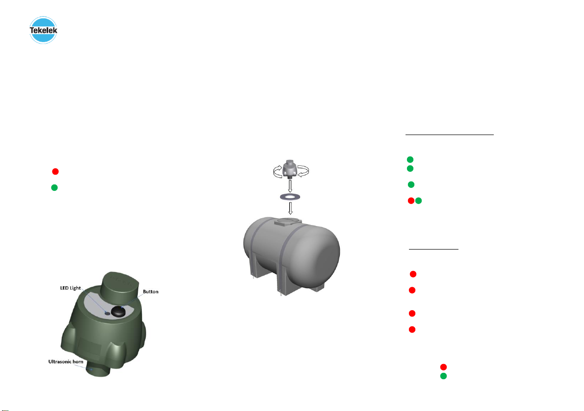
STEP 2: Attaching the sensor to your tank:
a. Identify a spare threaded opening (typically 2”).
Remove and store the cap.
b. Ensure the opening is located away from the sides of
the tank and is clear of internal obstructions to
ensure a good ultrasonic reading. See Appendix for
further details.
c. Ensure the rubber seal (see diagram) is placed
between the opening and threaded adapter.
d. Screw the sensor clockwise into the threaded
opening.
Note: This sensor is not suitable for submersion in water.
NOTE: For the external antenna option self-amalgamating tape is
required to seal the external antenna (SMA) connections. See
Step 4.
DO NOT OVER-TIGHTEN THE SENSOR (Hand tight only).
Technical Specifications
Supports LoRaWan 1.0.2 compliant125 / 250KHz bands.
Operating frequency: 868MHz
Fits onto tanks with a 2” BSP threaded opening. 1 1/2” or
1 1/4” adapters are available.
Power output maximum 14dBm
Up to 14 years battery life using a 3.6v 2/3AA Li-SOCL2 cell
Operational temperature range –20 to +50° C
Dimensions 118mm x 90mm. Weight 250g
STEP 3: Manually testing the sensor:
Once the sensor has been installed successfully, it is
recommended to force a manual connection 4-5 times to test
the communications strength of the radio signal.
a. Press and hold the button for approximately 1
second, until the LED turns green.
b. Wait approximately 10-20 seconds and observe if the
LED flashes green or red.
c. Green flashes indicate a successful test connection
and data transmission.
d. Red flashes mean an unsuccessful connection.
See the following for description of Green/Red LED
flash codes.
LED Radio Signal Strength Flash Code
After a manual transmission is successfully completed, the
sensor LED will flash GREEN to indicate RF quality:
X 3 Flashes: Excellent signal strength quality (> -110dBm).
X 2 Flashes: Good signal strength quality (< -110 dBm & > -
115dBm).
X 1 Flash: Adequate signal strength quality (<-115dBm & > -
119dBm).
Alternate Flash: Weak RF signal: try 5 times and if this
response is stable then it’s deemed adequate. If the sensor
shows some double red flashes during this signal strength test -
then an external antenna should be tried. It may need to be
elevated for best performance.
LED Error Flash Code
If a manual activation fails to connect successfully, the red LED
will flash the following code:
X 1 Flash: LoRaWAN network Join Fail. The unit may not be
registered on the network. Contact supplier.
X 2 Flashes: No Response from LoRaWAN network. This
occurs if unit is not registered, no radio reception or response
timeout
X 3 Flashes: General error, please try again. If the error
persists then contact the supplier for support.
X 5 Flashes: Maximum number of allowed button presses
exceeded (up to 6 button presses per hour allowed).
= Red LED Flash
= Green LED Flash
2
9-5848-06
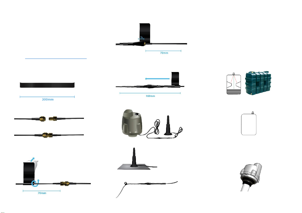
STEP 4: External antenna installation:
The external antenna should be elevated and clear of near
obstacles for best performance. The antenna should be mounted
on a magnetic surface (at least 15cm2 area) for best
performance. The antenna requires self-amalgamating tape to
seal the antenna cable joint - Note: This cable joint, while water
resistant, should not be submerged in water. The YouTube link
(page 4) shows the recommended application of the sealing tape.
Instructions and Link for sealing the SMA connector.
Video Link: https://www.youtube.com/watch?v=RG6XjjlGnEk
Sealing SMA Connection Instructions
1. Cut 300mm of ‘Tesa’ (provided) self-amalgamating tape.
2. After fitting in the required site location, connect the SMA
connector from the Antenna to that of the sensor.
3. Start wrapping the tape 70cm away from the SMA connection.
The tape needs to be kept in tension by stretching and the clear
plastic backing of the tape should be unwrapped as the
installation proceeds.
4. Keep the tape stretched while wrapping, over-lapping half the
width of the previous turn.
5. Continue to wrap the tape to a distance of 70cm on the other
side of the SMA connector. Then reverse the direction and
continue to wrap back along to the starting point. Note: the tape
must be stretched for best performance.
6. See the sensor with sealed SMA connections (see the following
picture).
Excess cable can be looped and tie-wrapped as shown.
7. The antenna should be placed on a magnetic surface (larger
than 15cm2 area for best performance).
8. A P-clip (highlighted in the picture below) is supplied to secure
the antenna cable and keep the sealed joint away from any
standing water.
STEP 5: Waveguide installation:
The Ultrasonic LoRaWAN uses ultrasonic technology to
measure the liquid level of your tank. The ultrasonic
transducer requires a clear path with no obstacles in
order to function correctly.
In normal operation, the Tank sensor is directly attached to the
tank as outlined in STEP 2. The appendix at the end of this
document outlines the recommended ultrasonic clearance
path for optimum performance.
However, there are many tanks that have internal obstructions
such as pipes, baffles or structural bracing that can cause
reflections at different liquid levels (as shown in the following
graphics).
Additionally, some Tank installations have mounting points for
the Tank sensor that are close to the edge of the tank (as
shown in the following graphic). This will also present
difficulties for the ultrasonic signal detection.
The recommended solution for these use cases is the
installation of a waveguide around the horn of the tank sensor.
The waveguide is a tubular pipe that is connected to an
adapter on the Ultrasonic sensor and extends close to the floor
of the tank (it is cut to match the tank height). This pipe
constrains the ultrasonic signal to within the pipe and avoids
issues with signal reflections as outlined previously.
3
9-5848-06
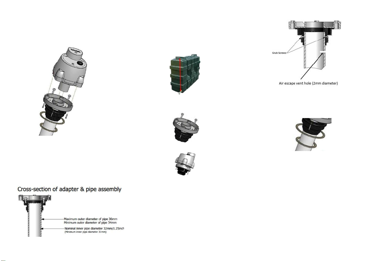
The Ultrasonic LoRaWAN waveguide kit is supplied by Tekelek and
comprises of the accessories needed to connect a waveguide to
the ultrasonic sensor.
The below ‘exploded’ view shows the accessories and the
assembly method. The waveguide should be assembled as
follows:
Waveguide Assembly Instructions
1. Source a suitable pipe to act as the waveguide.
This pipe should conform the dimensions in the figure
below in order to fit the adapter.
The recommended pipe material is PVC (domestic
waste pipe is often used).
Other materials are possible but should checked for
chemical resistance to fuel oil.
2. The pipe should be cleanly cut to length. The length
required should be measured from the top of the tank
(where the sensor is to be mounted) to that of the fuel
outlet point (as shown).
Note: The bottom of the pipe should be a minimum of
5cm from the base (floor) of the tank to prevent it
from touching in the case of tank dimensional changes
due to temperature etc.
3. The waveguide pipe adapter comes attached to the
base adapter as shown in the graphic.
The pre-existing 2’’ adapter should be removed from
the sensor and replaced with the pipe adapter.
4. The adapter should be attached to the ultrasonic
sensor base with M3.5x10 Pozi screws x 4.
5. The waveguide pipe should be securely attached via
the two grub screws and hand tightened with an
M1.5 Allen key (Note: over-tightening the grub screws
can damage the plastic).
Care should be taken to keep the sensor and pipe
vertically aligned and supported, while fitting during
the installation.
Note: Depending on the weight, length and surface
finish of the pipe, it may be necessary to glue it into
position. In this case a hole should be drilled near the
top of the waveguide pipe, just below the adapter, to
ensure that any trapped air can exit.
6. Insert the correctly sized rubber seal ring, as
required for the tank opening (supplied), and
position it on the face of the adapter that is
screwed onto the top of the tank.
7. Insert the whole assembly carefully into the tank,
taking care not to loosen the pipe, and fit into
position. Hand tighten the assembly until the
rubber seal locks into position.
8. The use of a waveguide requires that the Ultrasonic
LoRaWAN sensor be configured with a waveguide
ultrasonic profile from the LoRaWAN server.
Note: the default sensor configuration is non-
waveguide mode and the measurements will be
inaccurate unless a waveguide configuration mode is
used.
Note: The use of this Waveguide option is limited to a
range of 3m and not 4m as per standard operation.

4
9-5848-06
APPENDIX:
Ultrasonic device path clearance requirements
Avoid obstacles in the area outlined by the conical shape.
The table details the required clearance range as the ultrasonic signal
diverges.
Height
(CMs)
Width (CMs)
Ultrasonic signal from transducer clearance
area
10
5.36
20
10.72
30
16.08
w=0.53 x h
40
21.44
50
26.79
60
32.15
70
37.51
80
42.87
90
48.23
100
53.59
110
58.95
120
64.31
130
69.67
Examples where caution regarding the
installation should be observed
140
75.03
150
80.38
160
85.74
170
91.10
180
96.46
190
101.82
200
107.18
210
112.54
220
117.90
230
123.26
240
128.62
250
133.97
260
139.33
Find a position which
respects the ultrasonic
signal –avoid internal
structures such as pipes,
baffles, bracing structures
etc.
Do not install
too close to the
edge.
270
144.69
280
150.05
290
155.41
300
160.77
Note: In the above, a sensor should be installed at least 0.5w from the inner
wall of a tank
For example, a 2m height tank would require 0.53m clearance from the
sidewalls of the tank for best performance.
w
h
Other TEKELEK Accessories manuals


