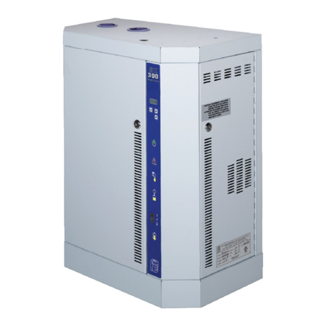
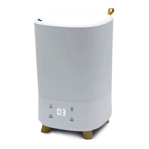
SK300 Steam Humidifier
Installation Instructions and User Manual
www.neptronic.com Page | ii
Handling and Lifting
Lifting or handling MUST be carried out by trained and qualified personnel. Ensure that the lifting
operation has been properly planned, assessed for risk and that the equipment has been checked by
a competent Health & Safety representative, and effective control measures are in place.
It is the customer’s responsibility to ensure that the operators are trained in handling heavy goods and
to enforce the relevant lifting regulations.
The Steam Humidifier MUST always be handled and lifted with care and should remain in its original
packaging for as long as possible prior to installation.
The Steam Humidifier package may be carried using a forklift from the underside. Caution should be
exercised to ensure balanced load before lifting.
Unpacking
The Steam Humidifier is shipped inside carton boxes or in a wooden crate. Remove packing and skids prior to
commissioning.
Lists
Illustrations
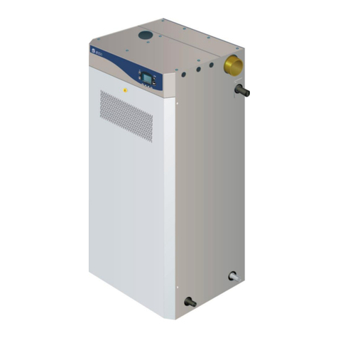
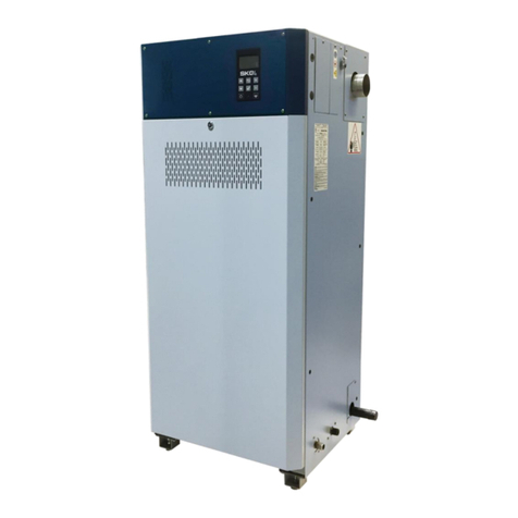
Illustration 1 - Overview of the Humidifier ......................................................................................................................... 1
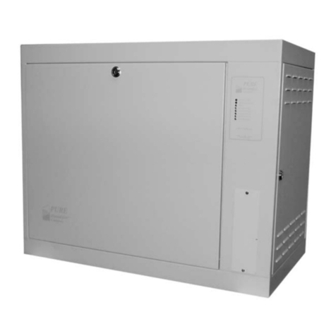
Illustration 2 - Steam Humidifier with Space Distribution Unit........................................................................................... 2
Illustration 3 - Weather Proof Enclosure............................................................................................................................ 3
Illustration 4 - Positioning the Humidifier........................................................................................................................... 4
Illustration 5 - Weather Proof Enclosure Unit .................................................................................................................... 6
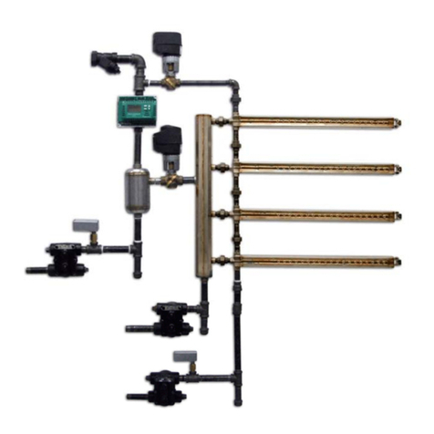
Illustration 6 - Steam Absorption Manifold (S.A.M) Horizontal Duct ................................................................................. 6
Illustration 7 - Steam Absorption Manifold (S.A.M.E2) Horizontal Duct ............................................................................ 7
Illustration 8 - Steam Absorption Manifold (S.A.M. or S.A.M.E2 ) Vertical Duct ............................................................... 7
Illustration 9 - Multi Steam System.................................................................................................................................... 7
Illustration 10 - Duct Hole Dimensions and Minimum Distance ........................................................................................ 8
Illustration 11 - 1 ⅜’’ (35mm) Diameter Pipe Placement: Horizontal Duct ........................................................................ 9
Illustration 12 - 2 ⅛’’ (51mm) Diameter Pipe Placement: Horizontal Duct ........................................................................ 9
Illustration 13 - Eyelet Orientation ..................................................................................................................................... 9
Illustration 14 - 1 ⅜’’ (35mm) Diameter Pipe Placement: Vertical Duct .......................................................................... 10
Illustration 15 - 2 ⅛’’ (51mm) Diameter Pipe Placement: Vertical Duct .......................................................................... 10
Illustration 16 - Steam Output Connections: Typical Installation..................................................................................... 11
Illustration 17 - Steam Output Connection: Incorrect Installation.................................................................................... 11
Illustration 18 - Steam Separator (S trap) Installation ..................................................................................................... 12
Illustration 19 - SDU mounted on Humidifier................................................................................................................... 13
Illustration 20 - SDU Remote Installation ........................................................................................................................ 14
Illustration 21 - Plumbing Connections............................................................................................................................ 15
Illustration 22 - Water Supply Connections ..................................................................................................................... 16
Illustration 23 - Weather Proof Enclosure Plumbing: Front View .................................................................................... 17
Illustration 24 - Weather Proof Enclosure Plumbing: Side View ..................................................................................... 17
Illustration 25 - One and Three Phase Power Connections............................................................................................ 18
Illustration 26 - Low Voltage Control Connections .......................................................................................................... 19
Illustration 27 - Connection to HRO20 humidistat or HRO20 with remote humidity sensor (SHR10 or SHC80)............ 19
Illustration 28 - Humidity controlled by humidifier with SHR10 or SHC80 as space sensor ........................................... 20
Illustration 29 - VAV system with humidity controlled by humidifier using Hi limit sensor and space sensor................. 20
Illustration 30 - Humidity Signal 0-10 Vdc ....................................................................................................................... 21
Illustration 31 - Humidity Signal 2-10 Vdc ....................................................................................................................... 21
Illustration 32 - Humidity Signal 4-20 mA ........................................................................................................................ 21
Illustration 33 - Control Signal 0 to 10 Vdc...................................................................................................................... 22
Illustration 34 - Control Signal 2 to 10 Vdc...................................................................................................................... 22
Illustration 35 - Control Signal 4-20 mA .......................................................................................................................... 22
Illustration 36 - Common Alarm Connections.................................................................................................................. 23
Illustration 37 - Controls Placement (Steam Dispersed into a Duct or AHU) .................................................................. 23
Illustration 38 - Display Features: Front Panel ................................................................................................................ 24
Illustration 39 - Main PC Board ....................................................................................................................................... 28
Illustration 40 - Metal deposit dislodge during operation................................................................................................. 32
