5
S
SK
K3
30
00
0
h
hu
um
mi
id
di
if
fi
ic
ca
at
ti
io
on
n
m
ma
an
nu
ua
al
l
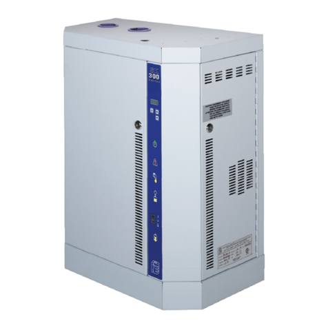
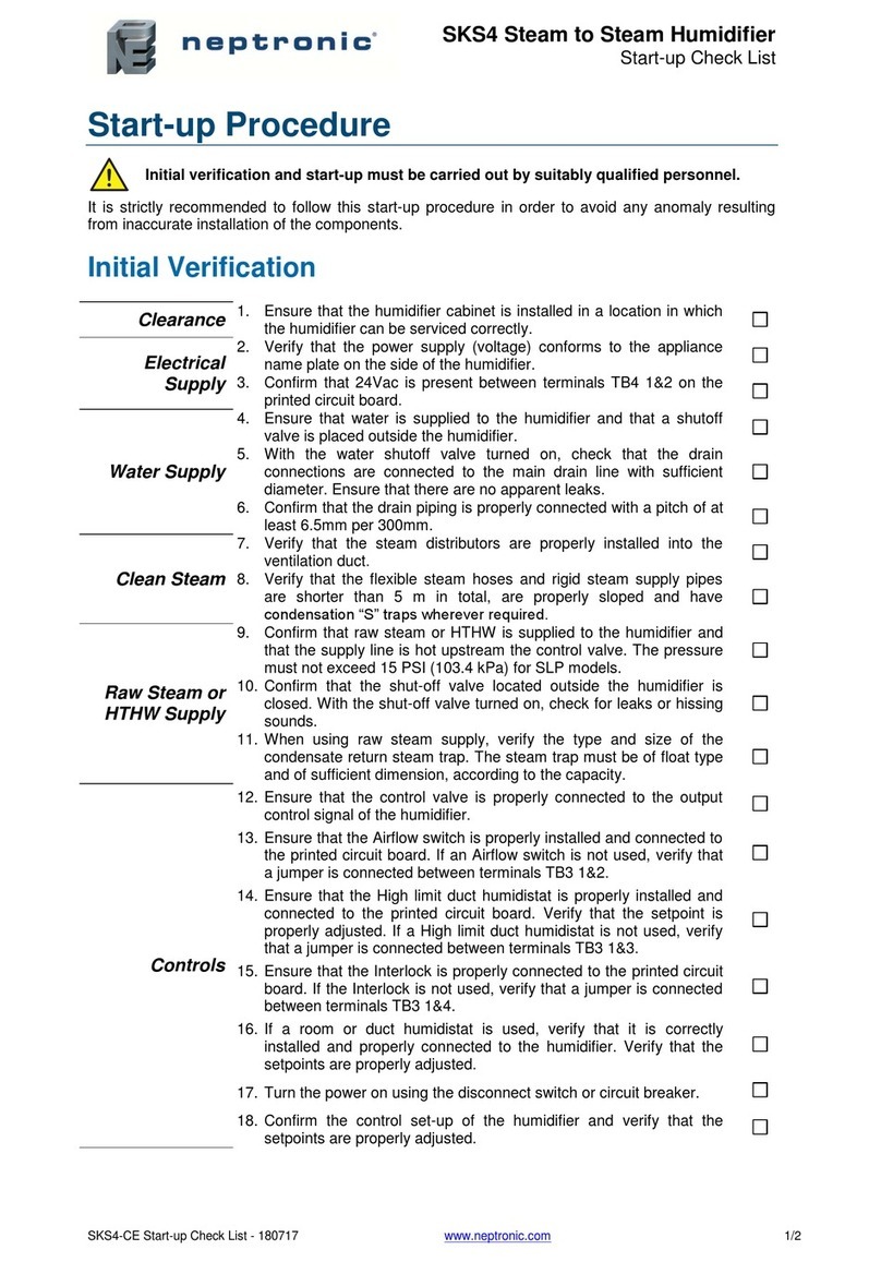
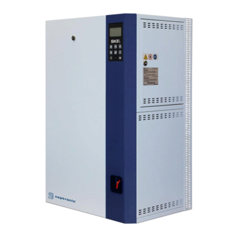
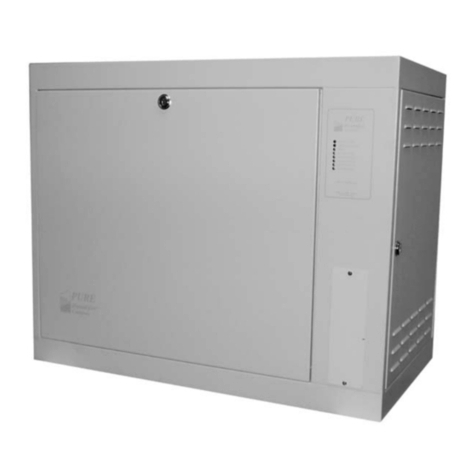
3.20 positioning of SK300:
To facilitate service, the unit must be easily
accessible from the front and right hand side.
The unit is to be mounted on a wall using key-
holes accessible from inside the mechanical
compartment (see mounting holes dimensions
section). The humidifier should be mounted
between 1.0m (39 inches) and 1.2m (48 inches)
above floor level. Leave a clearance of at least
25cm (10 inches) under the unit for installation
of water supply, drain piping, and electrical con-
nections. A clearance of at least 1.25m (50 inch-
es) from the front of the unit and 60cm (24 inch-
es) from the right hand side is necessary for
comfortable access and service. The humidifier
should be installed in a normally ventilated area,
and ambient temperatures should not exceed
300C (950F)
3.10 general recommendations:
The humidifier should be installed in an easily acces-
sible location to allow proper access for inspection
and maintenance. The unit should never be installed
in a location where an unusual malfunction of the
unit can cause damage to the structure of the build-
ing, or to very expensive equipment. Typically, the total
length of steam hose to the manifold should not exceed
5 meters (16 feet).
3.30 wall mounting:
The mounting of the humidifier on the wall is to be done by using the mounting keyholes accessible from inside
the mechanical compartment. Before installation, remove the steam container as described in the mainte-
nance instructions.
note: when marking pilot holes, make sure that the humidifier is level.
IMPORTANT
FOR SAFETY REASONS, POWER MUST BE
TURNED OFF AT THE EXTERNAL BREAK-
ER WHILE INSTALLING THE UNIT AND
BEFORE REMOVING OR DISCONNECTING
ANY ELECTRONIC OR MECHANICAL
COMPONENTS.
FAILURE TO DO SO IS DANGEROUS AND
WILL VOID THE WARRANTY.
3
3.
.0
00
0
p
po
os
si
it
ti
io
on
ni
in
ng
g
a
an
nd
d
i
in
ns
st
ta
al
ll
la
at
ti
io
on
n:
:
60cm
24 in
MIN
1m - 1.2m
39 - 48 in MIN
25cm
10 in
MIN
(fig. #2 )


