Neptune Technology TRICON SmartTrol Product manual

TRICON®SmartTrol™
Installation and Maintenance Guide


TRICON®SmartTrol™
Installation and Maintenance Guide

Copyright
This manual is an unpublished work and contains the trade secrets and confidential
information of Neptune Technology Group Inc., which are not to be divulged to third parties
and may not be reproduced or transmitted in whole or part, in any form or by any means,
electronic or mechanical, for any purpose, without the express written permission of
Neptune Technology Group Inc. All rights to designs or inventions disclosed herein, including
the right to manufacture, are reserved to Neptune Technology Group Inc.
Neptune engages in ongoing research and development to improve and enhance its products.
Therefore, Neptune reserves the right to change product or system specifications without
notice.
Trademarks used in this manual
Neptune and TRICON are registered trademarks of Neptune Technology Group Inc. SmartTrol
is a trademark of Neptune Technology Group Inc. Other brands or product names are the
trademarks or registered trademarks of their respective holders.
TRICON®SmartTrol™
Installation and Maintenance Guide
Literature No. IMSmartTrol 09.2021
Neptune Technology Group Inc.
1600 Alabama Highway 229
Tallassee, AL 36078
Tel: (800) 633-8754
Fax: (334) 283-7293
Copyright © 2013 - 2021
Neptune Technology Group Inc.
All Rights Reserved

Contents
Chapter 1: Introduction 1
Chapter 2: Typical Application 3
Chapter 3: Operating the SmartTrol™ 5
Display Total 5
Display Grand Total 5
Display Rate 6
Setup the SmartTrol™ 6
Chapter 4: General Description and Principles of Operation 7
Display 7
Resets 7
Presets 7
Relays 8
K Factor 8
Ratemeter 8
Counter 8
Lockout 8
RS-232C Communications 9
4-20 mA Output 9
Entering Decimal Points 9
Chapter 5: Specifications 11
Chapter 6: Mounting and Installation 13
Panel Mounting 13
Chapter 7: Connections to the SmartTrol™ 15
Power Connection For Alternating Current (AC) 15
Power Connection for Direct Current (DC) 15
Relay Output Connection 15
4-20 mA Option 15
Schematics 15
Chapter 8: Programming Worksheet 23
Chapter 9: Using the Worksheet 25
Counter 25
K Factor A and K Factor B (Counter) 25
TRICON®SmartTrol™Installation and Maintenance Guide iii

Fractional Units of Volume 25
Changing Units of Volume 26
Datalost 26
Reset to Zero or Set to Preset 26
Automatic or Manual Reset 26
Decimal Location 27
Ratemeter 27
K Factor A and K Factor B (Rate) 27
Changing Units of Times 28
Changing Units of Volume 28
Weight 28
Window 28
Significant Figures 29
Lock Out 29
OutPut Card 29
Unit Number 29
Serial or Parallel 29
Baud Rate 30
Parity 30
Analog Output 30
Relay Operation 30
Presets 31
Chapter 10: Setting Up the SmartTrol™ 33
Setting Up the Counter 33
Setting Up the Ratemeter 34
Setting Up the Lock Out Code 34
Setting Up the OUTCARD for RS-232 Communications 35
Setting Up the 4-20 mA OUTPUT 36
Setting Up the Relay Operation 36
Setting Up Preset A 37
Setting Up Preset B 37
Chapter 11: RS-232C Serial Communication Operations 39
PINAssignments 39
Command Code Definitions 40
iv TRICON®SmartTrol™Installation and Maintenance Guide
Contents

TRICON®SmartTrol™Installation and Maintenance Guide v
Example: Unit Number 1 41
Chapter 12: Warranty 43
Chapter 13: Assistance 45
By Phone 45
By Email 45
Appendix A: Specifications 47
47
48
49
50
50
51
51
52
52
TRICON/E® Performance Data
Trident® Turbine Performance Data
HP Turbine Performance Data
DISC Elements in Compound Meters
TRU/FLO® Compound Meter (Turbine Side)
Trident® PROTECTUS® (Turbine Side)
HP TRU/FLO® Compound Meter (Turbine Side)
HP PROTECTUS® III (Turbine Side)
TRU/MAG™ High Frequency Output / K Factor
TRU/MAG™ Pulse Rates 53
55
63
63
Appendix
B:
Communications
Program
Appendix
C:
TRICON®/S
Performance Data
Appendix
D:
Register
Tracking
65
Making the Total Agree with the Register 65
Overview of the Procedures 65
Preparing the SmartTrol™ to Accept the Current Register Reading 65
Enter the Current Register Reading 66
Setting the SmartTrol™ to Increment Total Keeping Pace with the Meter Register 66
Glossary 69
Index 73
Contents

This page intentionally left blank.
vi TRICON®SmartTrol™Installation and Maintenance Guide
Contents

Figures
1
3
13
16
16
17
18
19
20
21
Figure 1 – TRICON® SmartTrol™
Figure 2 – SmartTrol™ to Power Single TRICON/E® Transmitter
Figure 3 – SmartTrol™ Dimensions
Figure 4 – SmartTrol™ and Single TRICON/E® Transmitter (Pulse Output and Remote Reset)
Figure 5 – SmartTrol™ and Two TRICON/E® Transmitters (Pulse Output and Remote Reset)
Figure 6 – SmartTrol™ and 4-20 mA TRICON/E® and SmartChart
Figure 7 – SmartTrol™ with 4-20 mA Output Option and SmartChart and Single TRICON/E®
Transmitter with Pulse Output
Figure 8 – SmartTrol™ Powered by +24 VDC, Relays Controlling +24 VDC, and Single TRICON/E®
Transmitter with Pulse Output
Figure 9 – SmartTrol™ and Single TRICON®/S Transmitter (Pulse Output and Remote Reset)
Figure 10 – SmartTrol™ with 4-20 mA Output Option and Remote Device and Battery-Powered
TRU/MAG™
Figure 11 – SmartTrol™ with 4-20 mA Output Option and Remote Device and DC-Powered
TRU/MAG™ 22
TRICON®SmartTrol™Installation and Maintenance Guide vii

This page intentionally left blank.
viii TRICON®SmartTrol™Installation and Maintenance Guide
Figures

Tables
5
5
6
6
6
11
23
33
34
34
35
36
36
37
37
39
40
41
47
48
48
49
50
50
51
51
52
52
53
Table 1 – Display Total
Table 2 – Display Grand Total
Table 3 – Return to Total
Table 4 – Display Rate
Table 5 – Return to Total
Table 6 – Specifications
Table 7 – Example Programming Worksheet
Table 8 – Setting Up the Counter
Table 9 – Setting Up the Ratemeter
Table 10 – Setting Up the Lock Out Code
Table 11 – Setting Up the OUTCARD for RS-232 Communications
Table 12 – Setting Up the 4-20 mA OUTPUT
Table 13 – Setting Up the Relay Operation
Table 14 – Setting Up Preset A
Table 15 – Setting Up Preset B
Table 16 – Pin Assignments
Table 17 – Command Code Definitions
Table 18 – Example: Unit Number 1
Table 19 – TRICON/E® Performance Data (T-10)
Table 20 – TRICON/E® Performance Data (T-8)
Table 21 – Trident® Turbine Performance Data
Table 22 – HP Turbine Performance Data
Table 23 – DISC Elements in Compound Meters
Table 24 – TRU/FLO® Compound Meter (Turbine Side)
Table 25 – Trident® PROTECTUS (Turbine Side)
Table 26 – HP TRU/FLO® Compound Meter (Turbine Side)
Table 27 – HP PROTECTUS® III (Turbine Side)
Table 28 – TRU/MAG™ High Frequency Output / K Factor
Table 29 – TRU/MAG™ Pulse Rates
Table 30 – TRICON®/S Performance Data 63
TRICON®SmartTrol™Installation and Maintenance Guide ix


TRICON®SmartTrol™Installation and Maintenance Guide 1
Chapter 1: Introduction
The Neptune®SmartTrol™ is a versatile microprocessor-based controller for use with
TRICON/E®electronic registers. The main functions of the unit are to:
lDisplay rate and totalization values.
lControl relays for batching or alarming.
The SmartTrol allows two meter flows to be measured, separately scaled for both rate and
total, then combined into one overall rate and total. This dual input capability permits the
SmartTrol to be used with TRU/FLO®and PROTECTUS®meters having two separate
measuring elements to monitor flow.
Figure 1 – TRICON®SmartTrol™

This page intentionally left blank.
Chapter 1: Introduction
2TRICON®SmartTrol™Installation and Maintenance Guide
TRICON®SmartTrol™Installation and Maintenance Guide 3
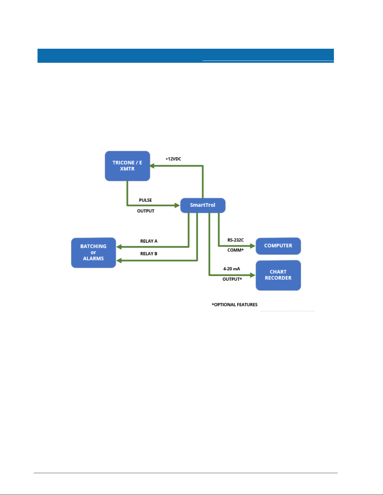
Chapter 2: Typical Application
In the following illustration, the SmartTrol™ powers a single TRICON/E®transmitter that
provides digital pulses to the SmartTrol. The SmartTrol scales the pulse input to determine
rate of flow and total quantity through the meter. The SmartTrol uses the rate of flow or
total values to operate two relays. The relays are used for single or two-stage batching, or
under / over alarming. You can order the SmartTrol with optional RS-232C serial
communications, or 4-20 mA analog output, or both.
Figure 2 – SmartTrol™ to Power Single TRICON/E®Transmitter

This page intentionally left blank.
Chapter 2: Typical Application
4TRICON®SmartTrol™Installation and Maintenance Guide
TRICON®SmartTrol™Installation and Maintenance Guide 5
Chapter 3: Operating the SmartTrol™
When you power on the SmartTrol™, it is in the normal operating mode. You can view
Total, Grand Total, and Rate.
To view Total, Grand Total, or Rate, apply power to one of the following displays.
Display Total
When you power on the SmartTrol, the current value of Total is displayed as indicated.
Until you select another variable, Total remains on the display. Total represents the volume
of liquid through the meter since Total was last reset. The value of Total is preserved when
you remove power from the SmartTrol and is restored when you reapply power.
Total is updated only while power is applied.
Display Description
Apply Power VER #. # Displayed 1 second.
N/A ######## Current value of Total.
Table 1 – Display Total
Display Grand Total
Grand Total represents the volume of liquid passing through the meter since Grand Total
was last reset. Like the value of Total, Grand Total is preserved when you remove power
from the SmartTrol, and is restored when you reapply power. Grand Total is updated only
while power is applied.
Press the key indicated in the table to display the Grand Total.
Press Display Description
ENT GRTOTAL Displayed 1 second.
N/A ######## Current value of Grand Total
blinks.
Table 2 – Display Grand Total

Press the key indicated in the table to return to the Total.
Press Display Description
ENT ######## Current value of Total.
Table 3 – Return to Total
Display Rate
When Rate is displayed, the first character position on the display is “R”. Rate represents
the volume of liquid passing through the meter in a unit of time (for example: gallons per
minute).
Press the key indicated in the table to display the Rate.
Press Display Description
C(Rate / Total) R ###### Current value of Rate.
Table 4 – Display Rate
Press the key indicated in the table to return to the Total.
Press Display Description
C(Rate / Total) ######## Current value of Total.
Table 5 – Return to Total
Setup the SmartTrol™
Before using the SmartTrol, you must program several setup values from the Setup Menu.
Fill out the Worksheet on Page 23 using the instructions beginning on Page 25.
Instructions for setting up the SmartTrol begin on Page 33. To enter the Menu from the
normal operating mode, press the “D” (MENU) key.
6 TRICON®SmartTrol™ Installation and Maintenance Guide
Chapter 3: Operating the SmartTrol™

TRICON®SmartTrol™Installation and Maintenance Guide 7
Chapter 4: General Description and Principles of Operation
This chapter provides a general description and the operating principles of the
TRICON®SmartTrol™.
Display
The SmartTrol shows one of three different variables on its eight-digit, alphanumeric
displays:
lTotal - the volume through the meter in gallons, cubic feet, or cubic meter units.
lGrand Total - similar to Total but continues to count when Total is reset.
lRate - the volume flowing through the meter per unit of time.
Since Rate and Total values are scaled independently, different units can be used for each.
For example: Rate displayed in gallons / minutes and Total in cubic feet.
Resets
A Reset returns the value of a Total or Grand Total to a predetermined point to begin
counting up to or counting down from. To Reset the Total or Grand Total, complete one of
the following:
lManually enter the value through the keypad and press the “CLR” key.
lRemotely enter the value by applying 3 to 30 VDC pulses for a minimum of 5 seconds to
Pin 5.
lUse a host computer via RS-232C communications.
The SmartTrol can be programmed to reset automatically when it reaches the endpoint.
Presets
Presets are the values of Total or Grand Total the totalizer must reach, or the Rate of flow
the ratemeter must register, to trigger relay operation. Total is configured to count up
from zero after a reset, or to count down from the preset value to zero after reset. Grand
Total only counts up from zero to the preset value after a reset.

Relays
The SmartTrol is used for monitoring or for control purposes, such as batching. There are
two control relays in the SmartTrol whose operations are based on preset values of Rate,
Total, or Grand Total. Each relay may be programmed to its own preset value. The presets
can be programmed to allow two-stage stepping of a process providing precise control of
a dispensing or blending application. For batching applications, an Auto Reset mode can
be selected for continuous blending processes. When Total or Grand Total values are
used, relay duration may be set from 1 to 99 seconds or minutes.
Relay operation is disabled when you enter the MENU function.
K Factor
The K Factor is divided into the input pulse to convert them into convenient units of
measurement. Separate K Factors are entered into the rate and counter sections of the
SmartTrol for each input, and K Factors may be mixed. Thus, you may batch (totalize) in
gallons and display Rate in cubic feet per hour.
Ratemeter
The ratemeter selection of the SmartTrol calculates Rate based on time between pulses
from a maximum of two inputs. The resulting value of input pulses per second is then
divided by the K Factor to display the Rate in units of volume per time.
Counter
The counter section of the SmartTrol divides pulses from a maximum of two inputs by the
Count K Factors to determine Total and Grand Total volumes through the meter in
convenient units of volume.
Lockout
After the SmartTrol is configured and operating, unauthorized changes can be prevented
by using a lock-out code to allow configuration modification. You can modify the code
periodically to maintain secure operations.
8 TRICON®SmartTrol™ Installation and Maintenance Guide
Chapter 4: General Description and Principles of Operation
Other manuals for TRICON SmartTrol
1
Table of contents
Other Neptune Technology Measuring Instrument manuals


Popular Measuring Instrument manuals by other brands


MFJ Enterprises
MFJ Enterprises MFJ-249D instruction manual

ABB
ABB FieldIT AquaMaster Quick reference guide

Abaxis
Abaxis VetScan HM5 installation instructions

Honeywell
Honeywell VERSAFLOW SONIC 1000/TWS 9000 Handbook

PCE Instruments
PCE Instruments PCE-360-ICA instruction manual

Bosch
Bosch GAM220MF Professional Original instructions


