Neptune Technology CMIU Product manual

Cellular MIU (CMIU™) Pit and Wall
Installation and Maintenance Guide


Cellular MIU (CMIU™) Pit and Wall
Installation and Maintenance Guide

Copyright
This manual is an unpublished work and contains the trade secrets and
confidential information of Neptune Technology Group Inc., which are not to be
divulged to third parties and may not be reproduced or transmitted in whole or
part, in any form or by any means, electronic or mechanical for any purpose,
without the express written permission of Neptune Technology Group Inc. All
rights to design or inventions disclosed herein, including the right to
manufacture, are reserved to Neptune Technology Group Inc.
Neptune engages in ongoing research and development to improve and
enhance its products. Therefore, Neptune reserves the right to change product
or system specifications without notice.
Trademarks Used in this Manual
ProRead and E-CODER are a trademarks of Neptune Technology Group Inc.
R900 is a registered trademark of Neptune Technology Group Inc.
E-CODER)R900iis a trademark of Neptune Technology Group Inc. Other brands
or product names are the trademarks or registered trademarks of their
respective holders.
FCCNotice
This device complies with Part 15 of the FCC Rules. Operation is subject to the
following two conditions:
lThis device may not cause harmful interference.
lThis device must accept any interference received, including interference that
may cause undesired operation.
Note:This equipment has been tested and found to comply with the limits for a
Class B digital device, pursuant to Part 15 of the FCCRules. These limits are
designed to provide reasonable protection against harmful interference in a
residential installation. This equipment generates, uses, and can radiate radio
frequency energy, and if not installed and used in accordance with the
instructions, may cause harmful interference to radio communications.
However, there is no guarantee that interference will not occur in a particular
installation. If this equipment does cause harmful interference to radio or
television reception, which can be determined by turning the equipment off and
on, the user is encouraged to try to correct the interference by one or more of
the following measures:
lReorient or relocate the receiving antenna.
lIncrease the separation between the equipment and receiver.

RF Exposure Information
This equipment complies with the FCC RF radiation requirements for
uncontrolled environments. To maintain compliance with these requirements,
the antenna and any radiating elements should be installed to ensure that a
minimum separation distance of 20 cm is maintained from the general
population.
Changes or modifications not expressly approved by the party responsible for
compliance could void the users' authority to operate the equipment.
Professional Installation
In accordance with section 15.203 of the FCCrules and regulations, the Meter
Interface Unit (MIU) must be professionally installed by trained meter installers.
Changes or modifications not expressly approved by the party responsible for
compliance void the user's authority to operate the equipment.
ISED Statement (Canada)
This device complies with Industry Canada license -exempt RSS standards.
Operation is subject to the following two conditions:
lThis device may not cause harmful interference.
lThis device must accept any interference received, including interference that
may cause undesired operation.
lThe device has been designed to comply with safety standards for exposure
to radio waves (SAR) in accordance to RSS-102.
lThe device should be installed and operated with a minimum distance of 20
cm between the equipment and the user's body.
Le présent appareil est conforme aux CNR d'Industrie Canada applicables aux
appareils radio exempts de licence. L'exploitation est autorisée aux deux
conditions suivantes:
(1) l'appareil ne doit pas produire de brouillage, et
(2) l'appareil doit accepter tout brouillage radioélectrique subi, même si le
brouillage est susceptible d'en compromettre le fonctionnement.
Cet artifice a été conçu pour se plier à la sécurité les exigences pour l'exposition
aux ondes radioélectriques (SAR) dans conformité avec RSS-102. Cet artifice
devrait être installé et fait marcher avec la distance minimale 20 centimètres
entre l'équipement et votre corps.

Cellular MIU (CMIU™)Pit and Wall
Installation and Maintenance Guide
Literature No. IMCMIU 04.19
Part No. 13682-001
Neptune Technology Group Inc.
1600 Alabama Highway 229
Tallassee, AL 36078
Tel: (800) 633-8754
Fax: (334) 283-7293
Copyright © 2003 - 2019
Neptune Technology Group Inc.
All Rights Reserved.
Firmware © 2016 - 2019
Neptune Technology Group Inc..
All Rights Reserved.

Contents
Chapter 1: Product Description 1
Chapter 2: Specifications 3
Electrical Specifications 3
Transmitter 3
Encoder Register Interface 3
Environmental 4
Functional 4
Dimensions and Weight 4
Chapter 3: General Installation Guidelines 7
Tools and Materials 7
Recommended Tools 7
Recommended Materials 8
Safety and Preliminary Checks 8
Verifying and Preparing the Encoder Register 8
Installing a Register (Non Pre-Wired or Potted Only) 9
Chapter 4: Wall Installation 13
Prior to Installation 13
Storage 13
Unpacking 13
Tools and Materials 14
Site Selection 14
Installing the CMIU™ 15
Removing the Main Housing 15
Applying the Scotchlok™ Gel Caps 16
Completing and Testing the Installation 18
Testing the Installation 19
Cellular MIU (CMIU™) Pit and Wall Installation and Maintenance Guide vii

Verifying the Meter Reading 21
Chapter 5: Pit Installation 23
Prior to Installation 23
Storage 23
Unpacking 23
Tools and Materials 24
Site Selection 24
Pit CMIU™ Installation 25
Installing the Antenna 26
Begin the Installation 27
Threading the F Connector 27
Installing the Scotchlok™ Connectors 29
Connecting the Splice Tube 32
Tying the Cable and Activating the CMIU™ 33
Testing the Installation 33
Chapter 6: Maintenance and Troubleshooting 35
Six Wheel Encoders 35
Four Wheel Encoders 35
Troubleshooting 35
Contact Information 36
By Phone 36
By Email 36
Appendix A: CMIU™ Modes 37
Appendix B: CMIU™ Manager 39
CMIU™ Status 39
Meter Reading 40
Cellular Network 40
Glossary 41
Index 43
viii Cellular MIU (CMIU™) Pit and Wall Installation and Maintenance Guide
Contents

Figures
Figure 1 – Cellular MIU – Wall 1
Figure 2 – Cellular MIU – Pit 1
Figure 3 – CMIU™ Pit Dimensions - Front and Side 4
Figure 4 – CMIU™ Wall Dimensions - Front and Side 5
Figure 5 – Wiring a Neptune Encoder Register 10
Figure 6 – CMIU™ Color Code for Wires 10
Figure 7 – Cable Threaded Around Strain Relief Posts 11
Figure 8 – Application of the Sealant 11
Figure 9 – Covering the Terminal Screws 12
Figure 10 – CMIU™ Back Plate 14
Figure 11 – CMIU™ Wall Kit 14
Figure 12 – CMIU™ Main Housing 15
Figure 13 – Gel Cap Connectors 16
Figure 14 – CMIU™ Color Code for Wires 17
Figure 15 – Cable in Back of Mounting Adapter 17
Figure 16 – Cable Exit Notch 18
Figure 17 – Securing the Mounting Adapter 18
Figure 18 – Swiping the CMIU™ 19
Figure 19 – CMIU™ Manager Options 19
Figure 20 – Selecting a CMIU™ 20
Figure 21 – Connecting the CMIU™ 20
Figure 22 – Signal Strength 21
Figure 23 – Meter Readings 21
Figure 24 – Installing the Seal Wire 22
Figure 25 – CMIU™ for Pit Installation 23
Figure 26 – Antenna Placement for Low Traffic Areas 24
Figure 27 – Antenna Placement for High Traffic Areas 25
Cellular MIU CMIU™Pit and Wall Installation and Maintenance Guide ix

Figure 28 – Inserting the Antenna into the Pit Lid 26
Figure 29 – Locking the Nut on the Antenna 26
Figure 30 – Antenna Installation Complete 26
Figure 31 – Antenna Connector 27
Figure 32 – Components of the Connector 27
Figure 33 – Tightening Connector and Latch Plate 28
Figure 34 – Cone-Shaped Gasket and Connector 28
Figure 35 – Scotchlok™ Connector 29
Figure 36 – CMIU™ Color Code for Wires 29
Figure 37 – Seating Connector Wires 30
Figure 38 – Crimping Tool 30
Figure 39 – Improper Connections 31
Figure 40 – Three Colored Wires Properly Connected 31
Figure 41 – Splice Tube 32
Figure 42 – Gray Wires in Slots 32
Figure 43 – Attaching the CMIU™ to the Antenna Shaft 33
Figure 44 – Swiping the CMIU™ 33
Figure 45 – CMIU™ Status Screen 39
Figure 46 – Meter Reading 40
Figure 47 – Cellular Network Screen 40
x Cellular MIU (CMIU™) Pit and Wall Installation and Maintenance Guide
Figures

Tables
Table 1 – Transmitter Specifications 3
Table 2 – Supported Encoder Maximum Cable Length 3
Table 3 – Environmental Conditions 4
Table 4 – Functional Specifications 4
Table 5 – Recommended Tools 7
Table 6 – Recommended Materials 8
Table 7 – Maximum Cable Lengths 15
Table 8 – Cable Length and Manufacturer 25
Table 9 – Example Reading Values 35
Table 10 – CMIU™ Modes 37
Cellular MIU (CMIU™) Pit and Wall Installation and Maintenance Guide xi

This page intentionally left blank.
xii Cellular MIU (CMIU™) Pit and Wall Installation and Maintenance Guide
Tables

Cellular MIU (CMIU™) Pit and Wall Installation and Maintenance Guide 1
Chapter 1: Product Description
This chapter provides a general description of the Neptune Cellular Meter Interface unit
(CMIU™) for wall and pit applications.
The CMIU is a network endpoint that collects meter reading data from an encoder register. It
then transmits the data for collection using 4G LTE cellular technology. The collection data is
stored and downloaded into the utility billing system for processing.
The CMIU is easily installed in wall or pit applications. It operates on AT&T or Verizon 4G LTE
cellular networks. The CMIU stops RF transmissions when the battery discharges below the
normal operating voltage.
Figure 1 – Cellular MIU – Wall
Figure 2 – Cellular MIU – Pit

This page intentionally left blank.
2 Cellular MIU (CMIU™) Pit and Wall Installation and Maintenance Guide
Chapter 1: Product Description

Cellular MIU (CMIU™) Pit and Wall Installation and Maintenance Guide 3
Chapter 2: Specifications
This chapter covers the specifications for the CMIU™.
Electrical Specifications
The power is supplied by a lithium battery.
Transmitter
The following table defines the CMIU transmitter specifications.
Specification Description
Transmit Period lBasic – hourly readings delivered every 24 hours
lAdvanced – hourly readings delivered every four hours
lPro – 15-minute readings delivered every hour
Encoder Reading 15-minute and 60-minute options
Output Power Meets FCC Part 15.247 and FCC Part 27
FCC Verification Part 15.247
Table 1 – Transmitter Specifications
Encoder Register Interface
The following table provides information on the maximum cable lengths required for
different registers.
Cable Brand Length
Neptune ARB®V300 feet (91 meters). Meets manufacturer's published
specifications for wire length between the encoder and the
remote receptacle. The length is based on solid three conductor
wire, 22 AWG.
Neptune®ProRead™ and
E-CODER®
500 feet (152 meters)
Sensus Protocol registers 200 feet (61 meters)
Table 2 – Supported Encoder Maximum Cable Length
Environmental
The following table provides the environmental specifications of the CMIU.
Condition Description
Operating Temperature –22° to 149°F (–30° to 65°C)
Storage Temperature –40° to 158°F (–40° to 70°C)
Operating Humidity 0 to 100% condensing
Table 3 – Environmental Conditions
Functional
The following table provides the functional specifications of the CMIU.
Specification Description
Register Reading Eight digits
MIU ID Nine digits
Table 4 – Functional Specifications
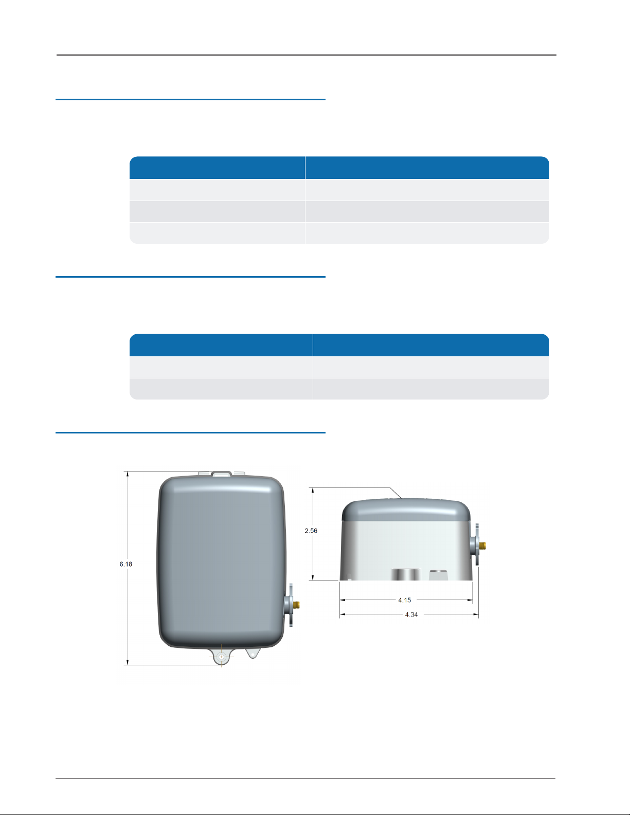
Dimensions and Weight
This section provides the dimensions and weight of the CMIU.
Figure 3 – CMIU™ Pit Dimensions - Front and Side
4 Cellular MIU (CMIU™) Pit and Wall Installation and Maintenance Guide
Chapter 2: Specifications

Figure 4 – CMIU™ Wall Dimensions - Front and Side
Cellular MIU (CMIU™) Pit and Wall Installation and Maintenance Guide 5
Chapter 2: Specifications

This page intentionally left blank.
6 Cellular MIU (CMIU™) Pit and Wall Installation and Maintenance Guide
Chapter 2: Specifications

Cellular MIU (CMIU™) Pit and Wall Installation and Maintenance Guide 7
Chapter 3: General Installation Guidelines
This chapter describes tools, materials, and general installation guidelines for the CMIU™.
Tools and Materials
Chapter 3 defines the recommended tools and materials you need to successfully install the
CMIU.
Some items may not apply to your specific installation, or the list may not contain
all required tools or materials.
Recommended Tools
The following table defines the tools recommended to install the CMIU.
Tool Description Use
Took Kit Contains standard tools including:
lAssorted screwdrivers
lNeedle-nose pliers
lWire stripper
lDiagonal cutters
lElectrician's knife
lHammer
lCrimping tool (part # 5500-158)
Perform various installation procedures
Magnet 6 lb. force (part # 12287-001) Activating the CMIU
CMIU Manager iOS application Manage, configure, and troubleshoot the
CMIU iOS application
Table 5 – Recommended Tools

Recommended Materials
The following table defines the materials recommended to install the CMIU.
Material Description Use
Cable Solid 3 Conductor #22 AWG (black /
green / red) (part # 6431-352)
Connect CMIUto encoder register.
Moisture
Protection
Compound
Novagard®sealant (part# 96018-072) Cover exposed wires and terminal
screws on register and CMIU.
Scotchloks Part# 8138-125 Connect wall CMIU or replacement
pit CMIU to encoder register.
Site Work Order Documentation provided by your utility Receive and record information
about the work site.
Table 6 – Recommended Materials
Safety and Preliminary Checks
Observe the following safety and preliminary checks before and during each installation:
lVerify that you are at the location specified on the site work order.
lVerify that the site is safe for you and your equipment.
lNotify the customer of your presence, and tell the customer that you need access to the
water meter.
lWrite the ID numbers of the CMIU you are installing, if the site work order does not
include the numbers.
lVerify that the ID numbers match the IDnumbers on the CMIU you are installing, if the
site work order already includes them.
Verifying and Preparing the Encoder Register
The CMIU is designed for use with the following encoder registers:
lARB®V
lProRead™
lProRead™ AutoDetect
lE-CODER®
lProCoder™
lMACH 10®
8 Cellular MIU (CMIU™) Pit and Wall Installation and Maintenance Guide
Chapter 3: General Installation Guidelines
Table of contents
Other Neptune Technology Measuring Instrument manuals

Neptune Technology
Neptune Technology T-10 User manual

Neptune Technology
Neptune Technology TRICON SmartTrol Product manual

Neptune Technology
Neptune Technology Pressure Spy User manual

Neptune Technology
Neptune Technology MACH 10 Product manual

Neptune Technology
Neptune Technology HP Fire Service Product manual
Popular Measuring Instrument manuals by other brands

Hundure
Hundure HTA-850 Series quick start guide

Hach
Hach sensION+ EC5 user manual

Apera Instruments
Apera Instruments WS200 instruction manual

KPS
KPS KPS-PA20 MINI instruction manual

Endress+Hauser
Endress+Hauser Micropilot NMR81 manual

Endress+Hauser
Endress+Hauser EngyCal RS33 Brief operating instructions


