Neptune R450 Product manual
E-Cod
E-Cod
R450™WALL AND PIT MIU INSTALLATION AND MAINTENANCE GUIDE
R450
™
Wall and Pit MIU Installation and Maintenance Guide


R450™ Wall and Pit MIU Installation and Maintenance Guide
This manual is an unpublished work and contains the trade secrets and confidential information of
Neptune Technology Group Inc., which are not to be divulged to third parties and may not be reproduced
or transmitted in whole or part, in any form or by any means, electronic or mechanical for any purpose,
without the express written permission of Neptune Technology Group Inc. All rights to designs or
inventions disclosed herein, including the right to manufacture, are reserved to
Neptune Technology Group Inc.
The information contained in this document is subject to change without notice. Neptune reserves the
right to change the product specifications at any time without incurring any obligations.
Trademarks Used in this Manual
R450 is a trademark of Neptune Technology Group Inc. Other brands or product names are the
trademarks or registered trademarks of their respective holders.
FCC Notice
This device complies with Part 15 of the FCC Rules. Operation is subject to the following two
conditions:(1) this device may not cause harmful interference, and (2) this device must accept any
interference received, including interference that may cause undesired operation.
“NOTE: This equipment has been tested and found to comply with the limits for a Class B digital device,
pursuant to Part 15 of the FCC Rules. These limits are designed to provide reasonable protection against
harmful interference in a residential installation. This equipment generates, uses, and can radiate radio
frequency energy and, if not installed and used in accordance with the instructions, may cause harmful
interference to radio communications. However, there is no guarantee that interference will not occur in a
particular installation. If this equipment does cause harmful interference to radio or television reception,
which can be determined by turning the equipment off and on, the user is encouraged to try to correct the
interference by one or more of the following measures:
• Reorient or relocate the receiving antenna.
• Increase the separation between the equipment and receiver.
• Connect the equipment into an outlet on a circuit different from that to which the receiver is con-
nected.
• Consult the dealer or an experienced radio/TV technician for help.”
RF Exposure Information
This equipment complies with FCC radiation exposure limits set forth for an uncontrolled environment.
This equipment should be installed and operated with minimum distance 20cm between the radiator and
your body. This transmitter must not be co-located or operating in conjunction with any other antenna or
transmitter.
Professional Installation
In accordance with section 15.203 of the FCC rules and regulations, the MIU must be professionally
installed by trained utility meter installers.
Changes or modifications to this device not expressly approved by
Neptune Technology Group Inc. could void the user's authority to operate the equipment.

Industry Canada
The term “IC” before the radio certification number only signifies that Industry Canada technical
specifications were met.
This Class B digital apparatus meets all requirements of the Canadian Interference Causing Equipment
Regulations. Operation is subject to the following two conditions: (1) this device may not cause harmful
interference, and (2) this device must accept any interference received, including interference that may
cause undesired operation.
Cet appareillage numérique de la classe B répond à toutes les exigences de l'interférence canadienne
causant des règlements d'équipement. L'opération est sujette aux deux conditions suivantes: (1) ce
dispositif peut ne pas causer l'interférence nocive, et (2) ce dispositif doit accepter n'importe quelle
interférence reçue, y compris l'interférence qui peut causer l'opération peu désirée.
To reduce potential radio interference to other users, the antenna type and its gain should be so chosen
that the equivalent isotropically radiated power (e.i.r.p.) is not more than that permitted for successful
communication.
This device has been designed to operate with the antennas listed below, and having a maximum gain of
0dB. Antennas not included in this list or having a gain greater than 0dB are strictly prohibited for use with
this device. The required antenna impedance is 75 ohms.
R450 Wall MIU Antenna (Neptune Technology Group, Inc. model number 12795-000)
R450 Pit MIU Lid Mount Antenna (Neptune Technology Group, Inc. model number 12796-100, 6 ft.,
12796-200, 25 ft.)
Copyright © 2008-2011
Neptune Technology Group Inc.
All Rights Reserved.
R450 Wall and Pit MIU
Installation and Maintenance Guide
Literature No. IM R450 MIU 07.11
Part No. 12857-001
Neptune Technology Group Inc.
1600 Alabama Highway 229
Tallassee, AL 36078
Tel: (334) 283-6555
Fax: (334) 263-7293


Contents
R450 Wall and Pit MIU Installation and Maintenance Guide v
1Product Description
Product Description . . . . . . . . . . . . . . . . . . . . . . . . . . . . . . . . . . . . . . . . . . . . . . . . . . . . . . . . . . . . . . . . . . . . 2
R450 MIU Programming. . . . . . . . . . . . . . . . . . . . . . . . . . . . . . . . . . . . . . . . . . . . . . . . . . . . . . . . . . . . . . 2
RF Protocol Error Detection . . . . . . . . . . . . . . . . . . . . . . . . . . . . . . . . . . . . . . . . . . . . . . . . . . . . . . . . . . . 2
Low Battery RF Emissions . . . . . . . . . . . . . . . . . . . . . . . . . . . . . . . . . . . . . . . . . . . . . . . . . . . . . . . . . . . . 2
2Specifications
Electrical Specifications . . . . . . . . . . . . . . . . . . . . . . . . . . . . . . . . . . . . . . . . . . . . . . . . . . . . . . . . . . . . . . . . . 3
Encoder Register Interface . . . . . . . . . . . . . . . . . . . . . . . . . . . . . . . . . . . . . . . . . . . . . . . . . . . . . . . . . . . 3
Specifications - R450 Wall MIU . . . . . . . . . . . . . . . . . . . . . . . . . . . . . . . . . . . . . . . . . . . . . . . . . . . . . . . . . . . 4
Environmental Conditions . . . . . . . . . . . . . . . . . . . . . . . . . . . . . . . . . . . . . . . . . . . . . . . . . . . . . . . . . . . . 4
Functional Specifications . . . . . . . . . . . . . . . . . . . . . . . . . . . . . . . . . . . . . . . . . . . . . . . . . . . . . . . . . . . . . 4
Dimensions and Weight . . . . . . . . . . . . . . . . . . . . . . . . . . . . . . . . . . . . . . . . . . . . . . . . . . . . . . . . . . . . . . 4
Specifications - R450 Pit MIU . . . . . . . . . . . . . . . . . . . . . . . . . . . . . . . . . . . . . . . . . . . . . . . . . . . . . . . . . . . . . 5
Environmental Conditions . . . . . . . . . . . . . . . . . . . . . . . . . . . . . . . . . . . . . . . . . . . . . . . . . . . . . . . . . . . . 5
Functional Specifications . . . . . . . . . . . . . . . . . . . . . . . . . . . . . . . . . . . . . . . . . . . . . . . . . . . . . . . . . . . . . 5
Dimensions and Weight . . . . . . . . . . . . . . . . . . . . . . . . . . . . . . . . . . . . . . . . . . . . . . . . . . . . . . . . . . . . . . 5
3General Installation Guidelines
Tools and Materials . . . . . . . . . . . . . . . . . . . . . . . . . . . . . . . . . . . . . . . . . . . . . . . . . . . . . . . . . . . . . . . . . . . . 6
Safety and Preliminary Checks . . . . . . . . . . . . . . . . . . . . . . . . . . . . . . . . . . . . . . . . . . . . . . . . . . . . . . . . 7
Verifying/Preparing the Encoder Register . . . . . . . . . . . . . . . . . . . . . . . . . . . . . . . . . . . . . . . . . . . . . . . . 7
Installing the Register (Non Pre-Wired or Potted Only) . . . . . . . . . . . . . . . . . . . . . . . . . . . . . . . . . . . . . . 8
4Installing the R450 Wall MIU
Prior to Installation . . . . . . . . . . . . . . . . . . . . . . . . . . . . . . . . . . . . . . . . . . . . . . . . . . . . . . . . . . . . . . . . . . . . 11
Storage. . . . . . . . . . . . . . . . . . . . . . . . . . . . . . . . . . . . . . . . . . . . . . . . . . . . . . . . . . . . . . . . . . . . . . . . . . 11
Unpacking . . . . . . . . . . . . . . . . . . . . . . . . . . . . . . . . . . . . . . . . . . . . . . . . . . . . . . . . . . . . . . . . . . . . . . . 11
Tools and Materials . . . . . . . . . . . . . . . . . . . . . . . . . . . . . . . . . . . . . . . . . . . . . . . . . . . . . . . . . . . . . . . . 12
Site Selection . . . . . . . . . . . . . . . . . . . . . . . . . . . . . . . . . . . . . . . . . . . . . . . . . . . . . . . . . . . . . . . . . . . . 12
Installing the R450 Wall MIU . . . . . . . . . . . . . . . . . . . . . . . . . . . . . . . . . . . . . . . . . . . . . . . . . . . . . . . . . 13

Contents
vi R450 Wall and Pit MIU Installation and Maintenance Guide
5Installing the R450 Pit MIU
Prior to Installation . . . . . . . . . . . . . . . . . . . . . . . . . . . . . . . . . . . . . . . . . . . . . . . . . . . . . . . . . . . . . . . . . . . . 17
Storage. . . . . . . . . . . . . . . . . . . . . . . . . . . . . . . . . . . . . . . . . . . . . . . . . . . . . . . . . . . . . . . . . . . . . . . . . . 17
Unpacking . . . . . . . . . . . . . . . . . . . . . . . . . . . . . . . . . . . . . . . . . . . . . . . . . . . . . . . . . . . . . . . . . . . . . . . 17
Tools and Materials . . . . . . . . . . . . . . . . . . . . . . . . . . . . . . . . . . . . . . . . . . . . . . . . . . . . . . . . . . . . . . . . 18
Site Selection . . . . . . . . . . . . . . . . . . . . . . . . . . . . . . . . . . . . . . . . . . . . . . . . . . . . . . . . . . . . . . . . . . . . 18
Connecting the Antenna. . . . . . . . . . . . . . . . . . . . . . . . . . . . . . . . . . . . . . . . . . . . . . . . . . . . . . . . . . . . . 20
6Activating and Testing the R450 MIU
Activating the MIU . . . . . . . . . . . . . . . . . . . . . . . . . . . . . . . . . . . . . . . . . . . . . . . . . . . . . . . . . . . . . . . . . . . . 23
RSSI Values and ARB®N_SIGHT™ FixedBase System Capabilities. . . . . . . . . . . . . . . . . . . . . . . . . . 24
Other Sample Configuration Emails . . . . . . . . . . . . . . . . . . . . . . . . . . . . . . . . . . . . . . . . . . . . . . . . . . . . 25
Completing the Activation. . . . . . . . . . . . . . . . . . . . . . . . . . . . . . . . . . . . . . . . . . . . . . . . . . . . . . . . . . . . 26
7Completing the R450 MIU Installation
Checklist. . . . . . . . . . . . . . . . . . . . . . . . . . . . . . . . . . . . . . . . . . . . . . . . . . . . . . . . . . . . . . . . . . . . . . . . . 27
8Troubleshooting
After the MIU Has Been Wired . . . . . . . . . . . . . . . . . . . . . . . . . . . . . . . . . . . . . . . . . . . . . . . . . . . . . . . . . . . 28
Troubleshooting Low RSSI: Tips and Techniques for New Installations . . . . . . . . . . . . . . . . . . . . . . . . 28
Troubleshooting Low RSSI: Tips and Techniques for Existing Installations . . . . . . . . . . . . . . . . . . . . . 29
Replacing the MIU Battery (Wall and Pit) . . . . . . . . . . . . . . . . . . . . . . . . . . . . . . . . . . . . . . . . . . . . . . . . . . . 30
Removing the Battery. . . . . . . . . . . . . . . . . . . . . . . . . . . . . . . . . . . . . . . . . . . . . . . . . . . . . . . . . . . . . . . 30
Cutting and Splicing the Battery Wires. . . . . . . . . . . . . . . . . . . . . . . . . . . . . . . . . . . . . . . . . . . . . . . . . . 31
Replacement Parts . . . . . . . . . . . . . . . . . . . . . . . . . . . . . . . . . . . . . . . . . . . . . . . . . . . . . . . . . . . . . . . . . . . . 33
Contact Information . . . . . . . . . . . . . . . . . . . . . . . . . . . . . . . . . . . . . . . . . . . . . . . . . . . . . . . . . . . . . . . . 34
Glossary
Index

R450 Wall and Pit MIU Installation and Maintenance Guide vii
Figures
Figure Title Page
1 R450 Wall and Pit MIU . . . . . . . . . . . . . . . . . . . . . . . . . . . . . . . . . . . . . . . . . . . . . . . . . . . . . . . . . . . 1
2 Wall MIU Dimensions . . . . . . . . . . . . . . . . . . . . . . . . . . . . . . . . . . . . . . . . . . . . . . . . . . . . . . . . . . . . 4
3 Pit MIU Dimensions . . . . . . . . . . . . . . . . . . . . . . . . . . . . . . . . . . . . . . . . . . . . . . . . . . . . . . . . . . . . . 5
4 Wiring a Neptune Encoder Register . . . . . . . . . . . . . . . . . . . . . . . . . . . . . . . . . . . . . . . . . . . . . . . . . 8
5 Encoder Wiring . . . . . . . . . . . . . . . . . . . . . . . . . . . . . . . . . . . . . . . . . . . . . . . . . . . . . . . . . . . . . . . . . 8
6 Cable Threaded Around Strain Relief Posts . . . . . . . . . . . . . . . . . . . . . . . . . . . . . . . . . . . . . . . . . . 9
7 Application of the Sealant . . . . . . . . . . . . . . . . . . . . . . . . . . . . . . . . . . . . . . . . . . . . . . . . . . . . . . . . 9
8 Covering the Terminal Screws . . . . . . . . . . . . . . . . . . . . . . . . . . . . . . . . . . . . . . . . . . . . . . . . . . . . 10
9 R450 Wall MIU Kit . . . . . . . . . . . . . . . . . . . . . . . . . . . . . . . . . . . . . . . . . . . . . . . . . . . . . . . . . . . . . 11
10 Wall MIU Main Housing . . . . . . . . . . . . . . . . . . . . . . . . . . . . . . . . . . . . . . . . . . . . . . . . . . . . . . . . . 13
11 Mounting Adapter . . . . . . . . . . . . . . . . . . . . . . . . . . . . . . . . . . . . . . . . . . . . . . . . . . . . . . . . . . . . . . 14
12 Back of MIU . . . . . . . . . . . . . . . . . . . . . . . . . . . . . . . . . . . . . . . . . . . . . . . . . . . . . . . . . . . . . . . . . . 14
13 Cable Exit Notch . . . . . . . . . . . . . . . . . . . . . . . . . . . . . . . . . . . . . . . . . . . . . . . . . . . . . . . . . . . . . . 15
14 Gel Cap Connections . . . . . . . . . . . . . . . . . . . . . . . . . . . . . . . . . . . . . . . . . . . . . . . . . . . . . . . . . . . 15
15 MIU Back Plate . . . . . . . . . . . . . . . . . . . . . . . . . . . . . . . . . . . . . . . . . . . . . . . . . . . . . . . . . . . . . . . 15
16 Hi-Lo Fastener . . . . . . . . . . . . . . . . . . . . . . . . . . . . . . . . . . . . . . . . . . . . . . . . . . . . . . . . . . . . . . . . 16
17 R450 Pit MIU Kit . . . . . . . . . . . . . . . . . . . . . . . . . . . . . . . . . . . . . . . . . . . . . . . . . . . . . . . . . . . . . . . 17
18 Antenna Placement for Low Traffic Areas . . . . . . . . . . . . . . . . . . . . . . . . . . . . . . . . . . . . . . . . . . . 18
19 Antenna Placement for High Traffic Areas . . . . . . . . . . . . . . . . . . . . . . . . . . . . . . . . . . . . . . . . . . . 19
20 Pit Antenna Cable and Housing . . . . . . . . . . . . . . . . . . . . . . . . . . . . . . . . . . . . . . . . . . . . . . . . . . . 20
21 Coax Connection . . . . . . . . . . . . . . . . . . . . . . . . . . . . . . . . . . . . . . . . . . . . . . . . . . . . . . . . . . . . . . 20
22 Latch Plate . . . . . . . . . . . . . . . . . . . . . . . . . . . . . . . . . . . . . . . . . . . . . . . . . . . . . . . . . . . . . . . . . . . 21
23 Rubber Seal . . . . . . . . . . . . . . . . . . . . . . . . . . . . . . . . . . . . . . . . . . . . . . . . . . . . . . . . . . . . . . . . . . 21
24 Connector Housing . . . . . . . . . . . . . . . . . . . . . . . . . . . . . . . . . . . . . . . . . . . . . . . . . . . . . . . . . . . . 21
25 Cable Tie . . . . . . . . . . . . . . . . . . . . . . . . . . . . . . . . . . . . . . . . . . . . . . . . . . . . . . . . . . . . . . . . . . . . 22
26 Pit Installation . . . . . . . . . . . . . . . . . . . . . . . . . . . . . . . . . . . . . . . . . . . . . . . . . . . . . . . . . . . . . . . . . 22
27 Magnet Activation of the MIU . . . . . . . . . . . . . . . . . . . . . . . . . . . . . . . . . . . . . . . . . . . . . . . . . . . . . 23
28 MIU Transmitter Cover . . . . . . . . . . . . . . . . . . . . . . . . . . . . . . . . . . . . . . . . . . . . . . . . . . . . . . . . . . 30
29 The Battery Compartment . . . . . . . . . . . . . . . . . . . . . . . . . . . . . . . . . . . . . . . . . . . . . . . . . . . . . . . 31
30 Battery Connection Cut . . . . . . . . . . . . . . . . . . . . . . . . . . . . . . . . . . . . . . . . . . . . . . . . . . . . . . . . . 31
31 Scotchloks Splicing Battery Wires . . . . . . . . . . . . . . . . . . . . . . . . . . . . . . . . . . . . . . . . . . . . . . . . . 32
32 Compartment Space . . . . . . . . . . . . . . . . . . . . . . . . . . . . . . . . . . . . . . . . . . . . . . . . . . . . . . . . . . . 32
33 Spliced Battery in Main Housing . . . . . . . . . . . . . . . . . . . . . . . . . . . . . . . . . . . . . . . . . . . . . . . . . . 32

viii R450 Wall and Pit MIU Installation and Maintenance Guide
Notes:
Figures

R450 Wall and Pit MIU Installation and Maintenance Guide ix
Tables
Table Title Page
1 Recommended Tools . . . . . . . . . . . . . . . . . . . . . . . . . . . . . . . . . . . . . . . . . . . . . . . . . . . . . . .6
2 Recommended Materials . . . . . . . . . . . . . . . . . . . . . . . . . . . . . . . . . . . . . . . . . . . . . . . . . . . .6
3 Cable Manufacturer, Length, and Gauge . . . . . . . . . . . . . . . . . . . . . . . . . . . . . . . . . . . . . . . 13
4 Cable Manufacturer and Length . . . . . . . . . . . . . . . . . . . . . . . . . . . . . . . . . . . . . . . . . . . . . . 19
5 Config Email Subject Line Breakdown . . . . . . . . . . . . . . . . . . . . . . . . . . . . . . . . . . . . . . . . . 24
6 Collector RSSI Uplink . . . . . . . . . . . . . . . . . . . . . . . . . . . . . . . . . . . . . . . . . . . . . . . . . . . . . .24
7 MIU RSSI Downlink . . . . . . . . . . . . . . . . . . . . . . . . . . . . . . . . . . . . . . . . . . . . . . . . . . . . . . .25
8 MIU RSSI Downlink . . . . . . . . . . . . . . . . . . . . . . . . . . . . . . . . . . . . . . . . . . . . . . . . . . . . . . .28
9 Collector RSSI Uplink . . . . . . . . . . . . . . . . . . . . . . . . . . . . . . . . . . . . . . . . . . . . . . . . . . . . . .28
10 Available Replacement Parts . . . . . . . . . . . . . . . . . . . . . . . . . . . . . . . . . . . . . . . . . . . . . . . . 33

x R450 Wall and Pit MIU Installation and Maintenance Guide
Notes:
Tables
R450 Wall and Pit MIU Installation and Maintenance Guide 1
1 Product Description
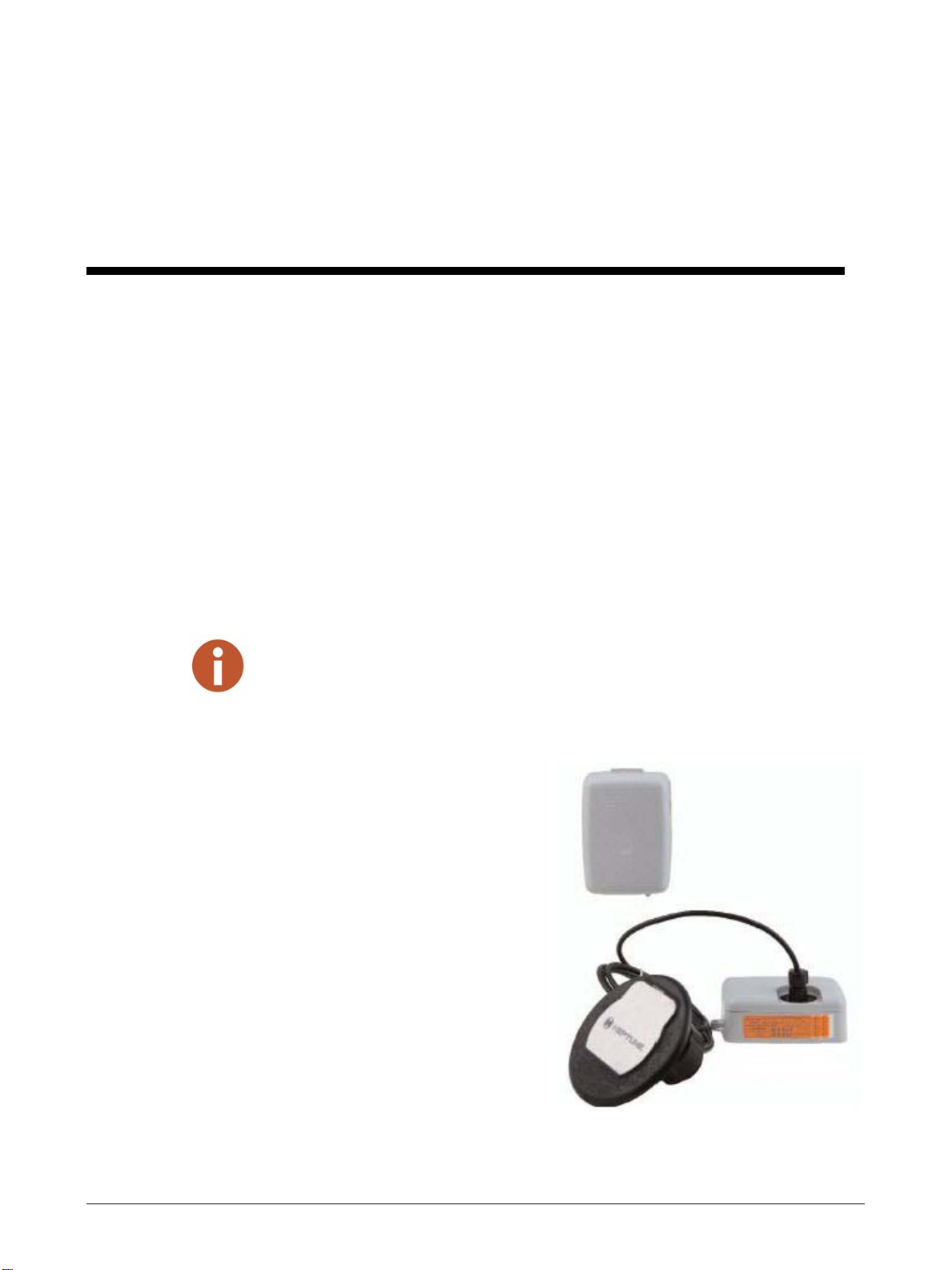
This section provides a general description of the R450™ Meter Interface Unit
(subsequently referred to as R450 MIU or MIU). The R450 MIU by Neptune is a compact
electronic device that collects meter reading data from an encoder register. It then
transmits the data for billing. The R450 MIU is designed for use with multiple types of
approved encoder registers:
• Neptune ARB®III, IV, and V
• ProRead™ and E-Coder®
• Sensus (Invensys) ECR® II and ECR®III.
Before installing the R450 MIU, the encoder register must be correctly wired and
programmed to work with the MIU.
To ensure that the ProRead register is
programmed for three-wire mode,
use the ProRead programmer and its
Radio Frequency (RF)/MIU 6, 8, or
10 ID Transport Driver Interface
(TDI) format. You can accomplish
this using the ProRead receptacle
before removing the receptacle or
three bare wires.
The R450 MIU is easy to install and
requires a Federal Communications
Commission (FCC) license to
operate. For information on obtaining
an FCC license, refer to “FCC
Licensing,” in the ARB®N_SIGHT™
FixedBase New Customer Guide.
Figure 1 R450 Wall and Pit MIU
• When using a ProRead encoder register (Rev. E or earlier), the ProRead register must be
programmed for three-wire mode.
• If using a new ProRead register (Rev. F or later), AutoDetect can recognize it, and it does not
need to be programmed.
• If using an existing register, make sure all three wires are connected, and it is programmed in
three-wire mode.

Product Description
2 R450 Wall and Pit MIU Installation and Maintenance Guide
Product Description
R450 MIU Programming
The MIU can be upgraded and configured. At the factory, serial numbers are programmed
into the MIU. Each MIU is given two unique serial numbers/identification numbers (two
IDs for compound units). Even numbers are given to the single registers and odd numbers
are given to a two-networked register unit. Custom serial numbers are not available.
RF Protocol Error Detection
The RF protocol is comprised of a header, data packet, and an error detection mechanism
that reduces the erroneous data.
Low Battery RF Emissions
The MIU does not produce out-of-band emissions under low battery conditions.

R450 Wall and Pit MIU Installation and Maintenance Guide 3
2 Specifications
This chapter provides you with the specifications for the R450 MIU.
Electrical Specifications
Encoder Register Interface
Supported Encoder Maximum Cable Length
Neptune ARB V1300 feet (91 meters)
Neptune ProRead (ARB VI)
and E-Coder (ARB VII)
500 feet (152 meters)
Sensus ECR II and ECR III2200 feet (61 meters)
Networked Neptune ProRead (ARB VI) /
E-Coder (ARB VII)
250 feet (76 meters)
1The length, which meets manufacturers’ published specification for wire length between encoder and
remote receptacle, is based on solid three-conductor wire, 22 AWG.
2Only specific formats of ECR III programming are compatible. Contact Neptune for details.
Specifications
4 R450 Wall and Pit MIU Installation and Maintenance Guide
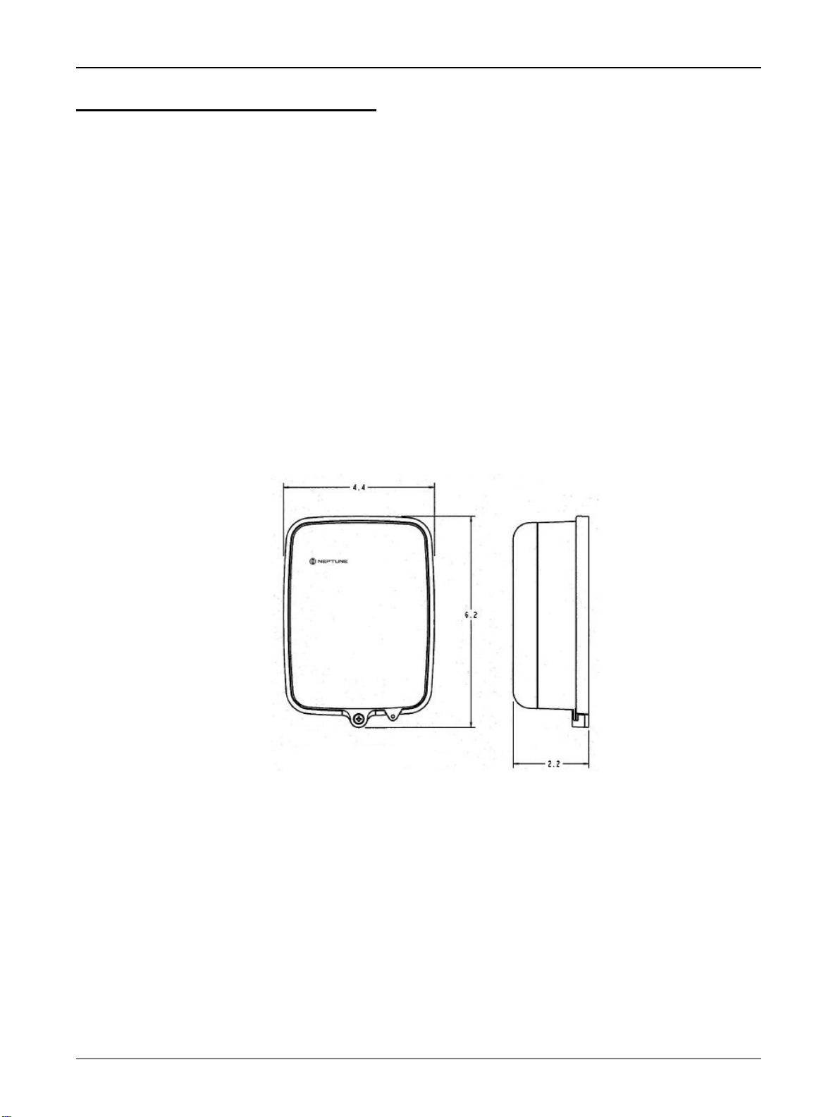
Specifications - R450 Wall MIU
Environmental Conditions
Functional Specifications
Dimensions and Weight
Figure 2 Wall MIU Dimensions
Operating temperature -22° to 149°F (-30° to 65°C)
Storage temperature -40° to 158°F (-40° to 70°C)
Operating humidity 0 to 95% Condensing
Register reading 3 - 8 digits
MIU ID 9 digits
Dimensions Refer to Figure 2
Weight 1.0 lbs. (454 grams)

Specifications
R450 Wall and Pit MIU Installation and Maintenance Guide 5
Specifications - R450 Pit MIU
Environmental Conditions
Functional Specifications
Dimensions and Weight
Figure 3 Pit MIU Dimensions
Operating temperature -22° to 149°F (-30° to 65°C)
Storage temperature -40° to 158°F (-40° to 70°C)
Operating humidity 0 to 95% Condensing
Register reading 3 - 8 digits
MIU ID 9 digits
Dimensions Refer to Figure 3
Weight 1.0 lbs. (454 grams)
6 R450 Wall and Pit MIU Installation and Maintenance Guide
3 General Installation Guidelines
This chapter describes tools, materials, and general installation information for the
R450 MIU.
Tools and Materials
Tables 1 and 2 show the recommended tools and materials you may need to successfully
install the R450 MIU or to replace the MIU’s internal battery.
Some items may not apply to your specific installation or the list may not contain all required tools
or materials.
Table 1 Recommended Tools
Item Description/ Recommendation Use
Tool kit Contains standard tools including:
• Assorted screwdrivers
• Needle-nose pliers
• Wire stripper
• Diagonal cutters
• Electrician’s knife
• Hammer
• Crimping tool
Part No: 5500-158
Various installation procedures
performed bythe utility
Magnet 6 lb. force
Part No: 12287-001
Activating the MIU
Installation tool Smartphone or cellular phone To receive emails
Table 2 Recommended Materials
Item Description/Recommendation Use
Cable Solid three-conductor,
#22 AWG (black/green/red)
Part No: 6431-352
Connecting the MIU to the
encoder register
Moisture
protection
compound
Novaguard sealant
Part No: 96018-072
Covering the exposed wires and
terminal screws on the register
and the MIU
General Installation Guidelines
R450 Wall and Pit MIU Installation and Maintenance Guide 7
Safety and Preliminary Checks
Observe the following safety and preliminary checks before and during each installation:
• Verify that you are at the location specified on the Site Work Order.
• Verify that the site is safe for you and your equipment.
• Notify the customer of your presence, and tell the customer that you will need access
to the water meter.
• If the Site Work Order does not have an MIU ID number on it, write in the ID
number(s) of the MIU you are about to install. If the Site Work Order already has an
MIU ID number on it, verify that it matches the ID numbers on the MIU you are
about to install.
Verifying/Preparing the Encoder Register
This R450 MIU is designed for use with the following encoder registers:
• ARB III, IV, and V
• ProRead (ARB VI)
• ProRead AutoDetect
• E-Coder (ARB VII)
• Sensus ECR II and ECR III
Before installing an MIU, the encoder register must be correctly wired and/or
programmed to work with the MIU. ProRead (ARB VI) encoder registers do not require
programming.
Connector Cable connector To connect the cable for the pit
antenna
Scotchloks™ Part No: 8138-125 Splicing the replacement battery
wire and connecting the wall MIU
or the replacement pit MIU to the
encoder register
Site work order Documentation provided by your utility Receiving and recording informa-
tion about the work site
When a ProRead (ARB VI) encoder register is used, the non-AutoDetect ProRead (ARB VI)
register must be programmed for three-wire RF mode.
Table 2 Recommended Materials
Item Description/Recommendation Use
General Installation Guidelines
8 R450 Wall and Pit MIU Installation and Maintenance Guide
If connecting the MIU to a new ProRead (ARB VI) encoder register, or if a three-
conductor cable is already connected to a ProRead (ARB VI) encoder register, ensure that
the ProRead (ARB VI) register is programmed for three-wire mode using the ProRead
(ARB VI) programmer and its RF/MIU 6, 8, or 10ID TDI format. This can be
accomplished through the ProRead (ARB VI) receptacle before removing the receptacle.
Installing the Register (Non Pre-Wired or Potted Only )
1 Before wiring the pit encoder register, make sure the cable is long enough. Then,
when the installation is complete, the pit lid can be removed easily without straining
the cable.
2 Use only 22 AWG cable to make the connection from the encoder register to the
MIU.
3 Remove the terminal screw cover from the encoder register.
4 Strip off 3/4” of jacket from the cable leaving only the three insulated wires.
5 Taking precautions not to nick or cut the insulation on the three wires, strip off 1/2”
of insulation from each of the three wires.
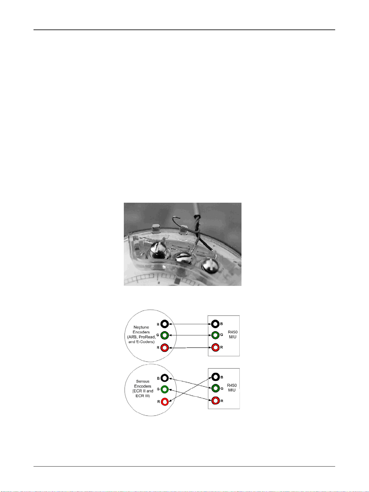
Figure 4 Wiring a Neptune Encoder Register
Figure 5 Encoder Wiring
Other manuals for R450
4
Table of contents
Popular Conference System manuals by other brands

Ocean Reef
Ocean Reef G.divers owner's manual

Siemens
Siemens optiPoint key module installation instructions

DIVELINK
DIVELINK COM-UC-8-20 Series manual

Yamaha
Yamaha PJP-20URs quick start guide

AVT
AVT MAGIC DC7 Hardware & software manual

GlobalMedia
GlobalMedia USB3.0 HD Video Conferencing Camera user manual


