SOFTLINK WB169-RFE-R User manual


Contents
1 Introduction 1
1.1 Wireless M-BUS Communication Protocol ................................ 1
1.2 Module usage ................................................. 1
1.3 Variants and ordering codes ......................................... 2
2 Technical parameters overview 3
3 Configuration of the WB169-RFE-R module 4
3.1 Configuration via the configuration cable ................................. 4
3.1.1 Connecting of module to computer ................................. 4
3.1.2 Using of ”PuTTy” freeware program for configuration ...................... 4
3.1.3 Basic commands of the Linux operating system .......................... 6
3.2 USB-CMOS converter driver installation .................................. 9
3.3 Configuration of the module individual parameters via cable ....................... 9
3.3.1 Configuration of the GateWay basic parameters .......................... 10
3.3.2 Configuration of GSM communication parameters ........................ 11
3.3.3 Configuration of WiFi communication parameters ........................ 12
4 Operational conditions 13
4.1 General operational risks ........................................... 13
4.1.1 Risk of mechanical damage ..................................... 13
4.1.2 Risk of electrical damage ...................................... 14
4.2 The condition of modules on delivery .................................... 14
4.3 Modules storage ............................................... 14
4.4 Safety precautions .............................................. 14
4.5 Environmental protection and recycling .................................. 14
4.6 WB169-RFE-R module installation ..................................... 14
4.7 Module replacement ............................................. 15
4.8 The module dismantling ........................................... 16
4.9 Functional check of the module ....................................... 16
4.10 Operation of the WB169-RFE-R module .................................. 17
4.11 Particularities of WiFi and GSM operation of the WB169-RFE-R module ............... 18
5 Troubleshooting 19
6 Additional information 21
List of Tables
1 Overview of WB169-RFE-R technical parameters ............................. 3
List of Figures
1 View of the WB169-RFE-R module ..................................... 2
2 Appearance of the USB-CMOS converter in Windows ”Device Manager” ................ 4
3 Configuration via USB port of computer .................................. 5
4 Terminal setting for serial line communication ............................... 5
5 Open terminal window for module configuration via serial line ...................... 5
6 Appearance of converter without driver in the Windows ”Device Manager” table ........... 9
7 Detailed view of WB169-RFE-R module .................................. 15
8 Example of WB169-RFE-R module ”Radar” table ............................ 17
9 Set of WB169-RFE-R module with external GSM communicator WG-LTE .............. 19
10 Quick test of gateway availability ...................................... 20
WB169-RFE-R (WB169-RFG-R, WB169-RFW-R) i

1 Introduction
This document describes features, parameters and setting possibilities of the WB169-RFE-R communication gate-
way, which is used for receiving of radio messages from the devices for remote reading of consumption meters
working in the communication system Wireless M-BUS (hereinafter referred as WMBUS) in the 169 MHz band and
for transmitting of these messages over a standard IP network (Internet) to a central collecting system.
1.1 Wireless M-BUS Communication Protocol
Wireless M-BUS is the communications protocol described by international standards EN 13757-4 (physical and
link layer) and EN 13757-3 (application layer), which is intended primarily for radio transmission of remote reading
values from consumption meters and sensors. Protocol Wireless M-BUS (hereinafter ”WMBUS”) is based on a
standard M-BUS definition (uses the same application layer as M-BUS standard), but is adapted for data transfer
via radio signals.
Communications via WMBUS protocol works in Master-Slave mode, where ”Master” is a collecting data device,
”Slave“ is a providing data device. Slave device could be integrated or external radio module transmitting data
from the meter/sensor. The communications protocol WMBUS defines several communication modes (simplex or
duplex). If working in simplex mode a ”Slave” device only transmits messages to ”Master” that these messages
receives. If working in ”bidirectional” mode, it is possible to use a back channel from ”Master” device to ”Slave”
device for ”Request” type of messages, that can contain e.g. request for the change of slave’s configuration.
Wireless M-BUS communications protocol partially supports repeating of the messages. If receiving from some
”Slave” device is not possible because of the low level of radio signal, the messages can be re-transmitted (repeated)
by appointed element of the radio network (repeater or slave with such functionality). Each repeated message is
marked as ”repeated message” so as not to be repeated again.
1.2 Module usage
The WB169-RFE-R module is intended for data transfer from the consumption meters (water meters, gas meters,
electricity meters, calorimeters) and a central computer application that receives and processes the data. The
module receives radio messages coded according to the Wireless M-BUS EN 13757-3 and EN 13757-4 standard for
the 169 MHz band, checks their correctness, encodes (”repacks”) them into IP/UDP frames and sends them to the
configured IP address and a central application port number. Inside the IP/UDP frames the data are coded by
using of Softlink’s proprietary ”NEP” protocol, so that the WB169-RFE-R module can be used for those central
applications only, which use ”NEP” coding system.
If the WB169-RFE-R module is setup for working in the N2 bidirectional communication mode, it could
transmit Wireless M-BUS messages of ”Request” type addressed to any subordinate module supporting N2 mode.
These messages can be used for remote changing of parameters of the subordinate ”Slave” device. Broadcasting of the
back-channel message for a particular ”Slave” device is under way during 500 ms long back-channel communication
window that opens immediately after transmitting of ”User Data” message from the device. During this time period
the ”Slave” activates its receiver so as to be able to receive a ”Request” message (if transmitted). Receiving of the
back-channel message is confirmed by ”Acknowledgment” type of message.
Management of ”Request” type of messages must be implemented into the central application software. These
messages addressed to the particular ”Slave” are transferred to the WB169-RFE-R module through the IP/UDP
protocol with using of ”NEP” coding. WB169-RFE-R module stores the ”Request” messages (that contain also
the lifetime period of each message) into its memory tables and after receiving of next ”User Data” message
from the ”Slave” device transmits the back-channel message within the communication window. If the message
is confirmed by receiving of ”ACK” message from the ”Slave”, the message is removed from the WB169-RFE-R
memory table. If ”ACK” message does not come, ”Request” is sent again during next window until its lifetime
period is elapsed. WB169-RFE-R module can keep just one message in the memory table, so if the module receives
another ”Request” message from the central application, stored message is replaced by new one so that only the
last message is transferred to the ”Slave”. ”Request” messages are coded by using of common M-Bus principles and
the coding system must be implemented in the central application as well as in the ”Slave” device in a specular
manner. The WB169-RFE-R module performs just transferring of the messages.
The basis of the module is a microcomputer with the Linux operating system, which is equipped with one 10/100
Mb/s Ethernet communication port, four USB (Universal Serial Bus) ports and one COM/CMOS config-
uration port. Communication ports are used for the following purposes:
•10/100 Mb/s Ethernet port – the main communication port intended for communication with the central
application over IP-network;
WB169-RFE-R (WB169-RFG-R, WB169-RFW-R) 1

•COM/CMOS port 115 kHz – the module configuration port;
•4 ports of USB 2.0 type – for connecting of external GSM or WiFi communication adapters (see paragraph 1.3)
The module is equipped with a slot for inserting of the external memory card of SD type, which is always
included in a delivery and it is an essential part of the device. The module radio receiver is equipped with the
coaxial connector of SMA (Female) type designated for interconnection of an external antenna (directly or via
coaxial cable). The module is enclosed in a plastic casing adapted for mounting on a DIN-rail. The box has a
standard ”circuit breaker” profile and width of six standard DIN-modules. The module needs an external power
supply 12V to 24V DC. For connecting of the power supply there is a screw terminal with marked voltage polarity.
Note: The manufacturer strictly recommends not removing the memory card from the module or to change or
replace it. The module is fully non-functional without the original SD card with the module’s firmware.
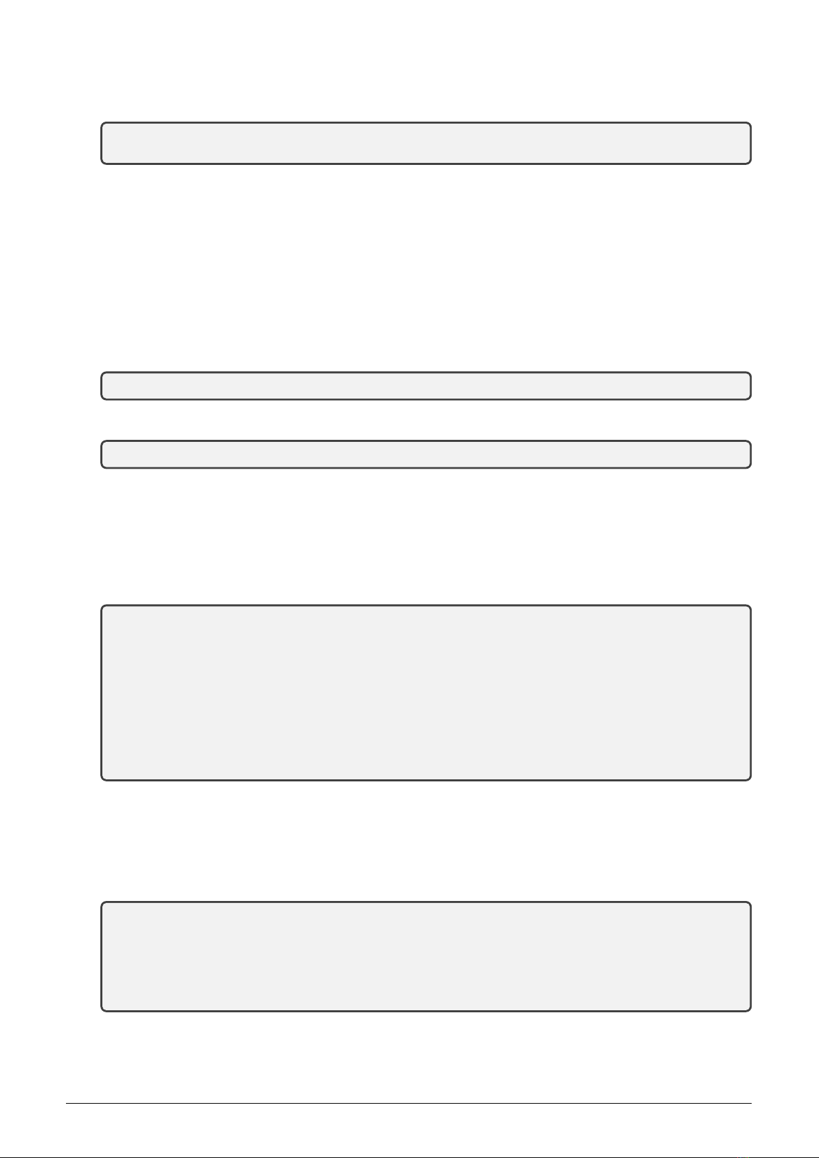
View of the WB169-RFE-R module is shown in Figure 1.
Figure 1: View of the WB169-RFE-R module
1.3 Variants and ordering codes
The WB169-RFE-R module can use three methods of local connection to the IP-network:
•direct connection to a local area network (LAN) of Ethernet type via the integrated 10/100 Mbps Ethernet
port;
•connection via a local wireless network (WLAN) WiFi 802.11 b/g/n with using an external adapter connected
to the USB port;
•connection via the mobile network GSM/GPRS/3G/4G (hereinafter referred as ”GSM”) using the external
adapter connected to the USB port.
The manufacturer supplies the WB169-RFE-R module based on customer requirements, either in a basic version
without external adapters, or with one of the above mentioned communication adapters. The module is always
equipped with complete software support for connecting of WiFi and GSM adapters, and it is always labelled as
WB169-RFE-R on the manufacturer’s label regardless whether and which adapters it is actually equipped with.
To order desired configurations of the WB169-RFE-R module use following ordering codes:
•WB169-RFE-R - is the ordering code for the module basic version without external adapters;
•WB169-RFW-R - is the ordering code for the version with the WiFi external adapter of Edimax EW-
7811Un type (or similar);
•WB169-RFG-R – is the ordering code for the version with the external GSM module of WG-LTE type.
The change of module’s hardware configuration can be performed additionally by adding the desired external com-
munication module/adapter. However, the manufacturer recommends ordering the required module configuration
(including appropriate adapter) so that the full equipment functionality (including adapter functionality) could be
completely tested before the delivery.
Note: The manufacturer does not recommend using other types of eternal modules/adapters, then those the
manufacturer currently delivers and whose functionality is properly tested. Types of currently supported adapters
can be checked at manufacturer by query.
WB169-RFE-R (WB169-RFG-R, WB169-RFW-R) 2

2 Technical parameters overview
Overview of all WB169-RFE-R module technical parameters is shown in the Table 1.
Table 1: Overview of WB169-RFE-R technical parameters
Transmitter and receiver parameters
Frequency band 169,400 ÷169,475 MHz
Modulation type 2GFSK, 4GFSK
No of channels in band 10
Transmission rate 2400, 4800, 19200 Baud
Receiver sensitivity -109 dBm
Back cghannel transmitting power 500 mW (*)
Antenna connector SMA female
Communication protocol Wireless M-BUS
Communication mode (by EN 13757-4) N1, N2 (*)
Communication interfaces
Ethernet 1 port 10/100 Mbps
USB 4 ports USB 2.0
Configuration interface RS232
Transmission speed 115 200 Baud
Operation mode asynchronous
Transmission rate 8 data bits, 1 stop bit, none parity
Signal level TTL/CMOS
Power supplying
External power supply (12 ÷24) V
Input power 4 W
Dimensions
Width 108 mm
Height 90 mm
Depth 58 mm
Weight cca 200 g
DIN case 6 modules
Storing and installation conditions
Installation environment (CSN 33 2000-3) normal AA6, AB4, A4
Operating temperatures range (-10 ÷50) ◦C
Storage temperatures range (0 ÷70) ◦C
Relative humidity 90 % (no condensation)
Degree of protection IP20
(*) Modules WB169-RFE-R with serial numbers 000001 to 000090 are not equipped with back channel transmitter
so they do not support N2 communication mode.
WB169-RFE-R (WB169-RFG-R, WB169-RFW-R) 3

3 Configuration of the WB169-RFE-R module
Configuration parameters of the WB169-RFE-R module can be displayed and changed from a common computer
(PC) equipped with USB port. This port can be interconnected with the WB169-RFE-R module configuration port
with using of the ”USB-CMOS” converter and configuration cable. Technique of interconnection of the module
with configuration computer and general rules of configuration are described in detail in the section 3.1. The
description and meaning of all configuration parameters can be found in the section 3.3 ”Setting of WB169-RFE-R
parameters via configuration cable”.
3.1 Configuration via the configuration cable
Configuration of the module can be performed by using of any PC with MS Windows or Linux operating systems
interconnected by configuration data cable. The module’s communication interface is of RS-232 (COM) type with
CMOS signal level. The ”CONFIG CMOS” configuration connector is placed on the module’s front panel.
3.1.1 Connecting of module to computer
For the interconnection with a USB port of computer it is necessary to use an manufacturer’s original configuration
cable with ”USB-CMOS” converter (see Figure 3). This converter creates a virtual serial port through the USB
interface and adapts voltage levels of the module’s configuration port to the standard USB port of common PC.
So as to to be able to create a virtual serial connection via USB interface, there must be a relevant driver installed
in the computer operation system. After the ”USB-CMOS” converter is connected to computer for the first time,
operating system will find and install appropriate generic driver of ”USB Serial Device” category automatically.
After driver installation is completed, the device will appear in the ”Ports (COM and LPT)” section of the ”Device
Manger” window as ”USB Serial Device (COMx)” (see figure 2).
Figure 2: Appearance of the USB-CMOS converter in Windows ”Device Manager”
As some of the older MS Windows versions do not support a generic driver for USB serial ports, the automatic
installation of the driver could fail (system reports ”Driver software installation failure”, or ”driver not found“).
In this case there is necessary to install the driver manually, following the steps in paragraph 3.2 ”Installation of
USB-CMOS converter driver”.
Insert USB-CMOS converter to the USB port of computer. Connect configuration cable to the ”CONFIG CMOS”
port on the module’s front panel. Thus the computer is connected with the module and ready for performing any
changes in configuration (see figure 3”Configuration via USB port of computer”).
3.1.2 Using of ”PuTTy” freeware program for configuration
The module configuration can be done with using of any suitable program for the serial line communication. The
description bellow is relevant for the open-source software ”PuTTY“ that is available for free on www.putty.org.
”PuTTY” software runs after clicking on the downloaded file ”putty.exe“. There will open a window of the terminal
communication (see Figure 4). For switching the program into the serial line communication, choose ”Serial” option
of the connection type in the ”Session” tab.
WB169-RFE-R (WB169-RFG-R, WB169-RFW-R) 4

Figure 3: Configuration via USB port of computer
Figure 4: Terminal setting for serial line communication
Check (or set up) the communication speed (”Speed”) to 115200 bits/s and then enter into the ”Serial line“ tab the
number of the serial port that the system automatically assigned to the virtual port at the moment of interconnection
module to the computer. The number of the serial port can be found in OS Windows by using of ”Device Manager”
(Control Panel/System and Maintenance/Device manager) by clicking on ”Ports (COM a LPT)” where the numbers
of ports appear (e.g. ”COM23” - see figure 2).
Click on ”Open” button in ”PuTTY” program and open the terminal window. After pressing of ”ENTER” key
there will appear a command prompt ”root@pi169-AAA:/#” which announces that the module is ready to be
configured (see figure 5).
Figure 5: Open terminal window for module configuration via serial line
WB169-RFE-R (WB169-RFG-R, WB169-RFW-R) 5

3.1.3 Basic commands of the Linux operating system
Activate a terminal window for configuration via configuration cable according to the instructions above. The
module WB169-RFE-R is equipped with the Linux operating system (OS). When configuring the module it is
necessary to know some basic OS commands and common procedures when working with OS Linux.
1. Login to the system
After connecting power supply to the module (or after completing a rebooting procedure) the system requires
a login and a password to enter. After booting of the operating system user is prompted for a login. Enter the
universal “root” login for the system administration and after the password is required enter initial password
”sladmin” for the WB169-RFE-R module administration. After entering login and password the module’s
command prompt ”root@pi169-AAA:/#” appears, where ”AAA” series is a module serial number.
An example of login:
Raspbian GNU/Linux 7 pi169-016 ttyAMA0
pi169-016 login: root
Password:
Linux pi169-016 4.1.6+ #810 PREEMPT Tue Aug 18 15:19:58 BST 2015 armv6l
The programs included with the Debian GNU/Linux system are free software;
the exact distribution terms for each program are described in the
individual files in /usr/share/doc/*/copyright.
Debian GNU/Linux comes with ABSOLUTELY NO WARRANTY, to the extent
permitted by applicable law.
root@pi169-016:~#
2. Movement in OS Linux directories
In OS Linux the directory can be changed either by direct entry of entire “path” from the root directory
(”root”), or by gradual movement in the directory up/down. For the change of directory the general command
in the form ”cd [path]” is used. If the path to the directory is entered ”from the root”, it always begins
with ”/” (slash). The command for transition from the current directory towards “down” to the lower level
directory (subdirectory) can be made by entry the subdirectory name after the command ”cd”. The command
for transition to the upper directory has the form of ”cd ..”.
An example of direct input of the directory:
root@pi169-016:/etc# cd /opt/gw/bin
root@pi169-016:/opt/gw/bin#
An example of gradual movement in a directory ”tree”:
root@pi169-016:/# cd opt
root@pi169-016:/opt# cd gw
root@pi169-016:/opt/gw# cd bin
root@pi169-016:/opt/gw/bin# cd ..
root@pi169-016:/opt/gw# cd ..
root@pi169-016:/opt# cd ..
root@pi169-016:/#
3. List of files in the directory
List of the current directory content can be displayed in OS Linux with using of the ”ls” command. After
entering the command the names of all the directories and files located in the current directory will display.
To display a list with more details of each subdirectory/file use ”ls -l” command (i.e. ”a long list”), In this
case subdirectories/files will be displayed in separate lines (the file line always begins with ”-”).
An example of a simple (”short”) directory list:
root@pi169-016:/opt/gw/bin# ls
nepgw setfreq setserial wmbus.xml
WB169-RFE-R (WB169-RFG-R, WB169-RFW-R) 6

An example of a detailed (”long”) directory list:
root@pi169-016:/opt/gw/bin# ls -l
total 156
-rwxr-xr-x 1 root root 143475 Sep 10 11:59 nepgw
-rwxr-xr-x 1 root root 451 Sep 10 12:00 setfreq
-rwxr-xr-x 1 root root 431 Sep 10 12:00 setserial
-rw------- 1 root root 1156 Sep 17 12:38 wmbus.xml
root@pi169-016:/opt/gw/bin#
4. Viewing of a file
To view the file in OS Linux use ”cat [name]” or ”less [name]” commands. Commands have a similar
meaning, the command ”less” makes possible a cursor movement in the list up and down. When enter one of
mentioned commands a text preview of the file is displayed.
An example of viewing a file ”wmbus.xml”:
root@pi169-016:/opt/gw/bin# less wmbus.xml
<?xml version="1.0" encoding="UTF-8"?>
<gw>
<xxx
<xxx
wmbus.xml
Viewing will be ended by entering of ”q” key .
5. Mounting disk (volume) in the read/write mode
After each start-up (or reboot) of the operating system memory disks/volumes are always mounted to the
system in the ”read only” mode. To edit a file on the dosk it is necessary to mount the disk (volume) to the
”read/write” mode. Mounting the volume in the ”read only” mode is performed by using of the ”mount -o
remount,ro [volume]”command. Mounting of the volume in the ”read/write” mode is performed by using
of the ”mount -o remount,rw [volume]”command. Commands can be entered from any directory.
An example of mounting iof the main (”/”) volume to ”read only” and ”read/write” mode:
root@pi169-016:~# mount -o remount,ro /
root@pi169-016:~# mount -o remount,rw /
An example of mounting of the ”/opt” volume to ”read only” and ”read/write” mode:
root@pi169-016:/opt/gw/bin# mount -o remount,ro /opt
root@pi169-016:/opt/gw/bin# mount -o remount,rw /opt
6. File editing by using of ”vi“ program
Change of some configuration parameters of the module WB169-RFE-R is performed by editing of a file, in
which the parameter is set-up. Editing can be performed with a commonly used ”vi” editor. Before editing
of the file it is necessary to remount the volume to the ”read/write” mode as it is described in the ”Mounting
disk (volume) in the read/write mode” article.
Editing of the file is run with using a command in a form of ”vi [filename]” as it is shown in the example of
editing of the ”wpa supplicant.conf” file:
root@pi169-016:/etc/wpa_supplicant# vi wpa_supplicant.conf
When entering the command the ”name” file opens in the browse mode. The file viewing is similar as under
entering the command ”cat” or ”less”. In the bottom line the file name displays; if the ”[readonly]” information
displays after the file name, the volume is in ”read only” mode and the file cannot be edited – see example:
~
"wpa_supplicant.conf" [readonly] 13L, 191C 1,1 All
WB169-RFE-R (WB169-RFG-R, WB169-RFW-R) 7
Switch the editor to editing mode by entering the ”i” command. In the bottom line information ”INSERT”
appears instead of the file name – see example:
~
-- INSERT -- 1,1 All
Editing is performed with the inserting of characters from the keyboard (they are always inserted in a place
before the cursor) or deletion of characters by pressing of “Backspace” key. After editing is finished use ”Esc”
and ”colon” (Esc:) keys to move back to the command mode (last line of file’s dump is replaced by colon and
cursor). When in command mode, use ”wq” command to save all changes and to exit the editor. If using the
”q!” command the editor is closed without saving of changes.
7. Starting the program (executive file)
In OS Linux a program can be started either from any directory by input of whole ”path” from the root
down to the executive file name (the command begins with a slash ”/”), or from the current directory (the
command begins with a dot and a slash ”./”).
An example of starting the ”nepgw” program by entering the entire path from the root:
root@pi169-016:/opt/vc# /opt/gw/bin/nepgw
An example of starting the ”nepgw” program from the current directory
root@pi169-016:/opt/gw/bin# ./nepgw
8. The system rebooting
The system rebooting is performed with the ”reboot” command entering from any directory. The command
can be used in specific cases, for example if the system does not respond to entered commands. The operating
system will pass the reboot process, connect disks in the ”read only” mode and after the entire process
completion requires to enter login and password.
An example of the system rebooting:
root@pi169-016:/# reboot
Broadcast message from root@pi169-016 (ttyAMA0) (Thu Oct 1 13:14:14 2015):
The system is going down for reboot NOW!
root@pi169-016:/#
xxx
[ 17.382493] EXT4-fs (mmcblk0p3): mounted filesystem with ordered data mode. Opts: (null)
Raspbian GNU/Linux 7 pi169-016 ttyAMA0
pi169-016 login:
9. Password change
The change of main directory (”root”) password can be performed by using of Linux standard ”passwd”
command entered from any directory. Before the change there is neccessary to mount the main volume (”/”)
to the ”read/write” mode as described in the ”Mounting of the disk (volume) in the read/write mode” article.
An example of the change of password including mounting of the disk in read/write mode:
root@pi169-016:~# mount -o remount,rw /
root@pi169-016:~# passwd
Enter new UNIX password:
Retype new UNIX password:
passwd: password updated successfully
root@pi169-016:~#
10. The system shutdown
In normal operation the system is proof against sudden disconnection of power supply and it is possible to
shutdown it without risks simply by disconnecting power supply only. But if the configuration takes place and
WB169-RFE-R (WB169-RFG-R, WB169-RFW-R) 8

some directories are mounted in ”read/write” mode, the manufacturer recommends carrying out controlled
shutdown using the ”poweroff” command entered from any directory. The operating system stores data and
shutdown safely. The shutdown process is completed by displaying a ”Power down” message, after which
power supply can be disconnected without risks.
An example of the system controlled shutdown:
root@pi169-016:/opt/gw/bin# poweroff
Broadcast message from root@pi169-017 (ttyAMA0) (Thu Sep 17 18:34:14 2015):
The system is going down for system halt NOW!
root@pi169-016:/opt/gw/bin#
[ 476.116539] reboot: Power down
3.2 USB-CMOS converter driver installation
If the computer operation system failed in automatic installing of the driver for the ”USB-CMOS”, it is necessary
to install the driver manually. The relevant current driver can be found on a chip manufacturer’s (FTDI) webpages,
namely in the ”VCP Drivers“ (Virtual COM Ports) section.
www.ftdichip.com/Drivers/VCP.htm
In the ”Currently Supported VCP Drivers” table find a link to a driver relevant to your operating system. To
download the file, click on a link in the table. After downloading the file (in .ZIP format) into any directory in
your computer, unzip the file. It will create a new folder (directory) with a set of files (e.g. ”CDM 2.08.24 WHQL
Certified”).
Connect the converter ”USB-CMOS“ to your computer and open a ”Device Manager” tool. The converter with the
disabled driver will be displayed in the top right corner of the window as ”Other Devices” (see figure 6left).
Figure 6: Appearance of converter without driver in the Windows ”Device Manager” table
Click by right mouse button on ”USB Serial Port” and choose ”Update Driver Software” option in the context menu.
Choose ”Find Driver in this computer” option in the ”Update Driver Software” window. Use ”Browse” button to
set up the path to the driver‘s folder (directory) and then click on the ”Next” button. The driver installation process
will launch. After the driver installation is completed, the standard ”Installation Completed” message will appear.
After the installation the converter will appear in the ”Ports (COM and LPT)” section of the ”Device Manager”
window (see figure 6right).
3.3 Configuration of the module individual parameters via cable
In this part of the document there are described the parameters of WB169-RFE-R module that can be checked
(read) and configured (changed) with using of ”USB-CMOS” configuration cable and PuTTy program as described
in the paragraph 3.1 of this document. Each part of the configuration is described in a separate paragraph.
Configuration of the WB169-RFE-R module parameters can be performed in three configuration files, where each
of them can be used for setting of specific group of parameters:
•in the ”wmbus.xml” file the basic parameters of the gateway are set (the module parameters, Wireless
M-BUS parameters and communications settings with the parent over IP-network);
•in the ”wvdial.conf ” file parameters for the GSM communication adapter are set;
•in the ”wpa supplicant.conf” file parameters for the WiFi communication adapter are set.
WB169-RFE-R (WB169-RFG-R, WB169-RFW-R) 9

3.3.1 Configuration of the GateWay basic parameters
In this part of configuration the basic parameters of gateway and Wireless M-BUS subsystem are set-up. The module
is factory-set to communicate with the central system ”CEM”. The configuration is stored in the ”wmbus.xml”
configuration file that is located in the ”/opt/gw/bin” directory. The current setting of the configuration can be
found out by the following method:
Go to the directory ”/opt/gw/bin”:
root@pi169-017:/etc# cd /opt/gw/bin
root@pi169-017:/opt/gw/bin#
View the configuration file ”wmbus.xml” by the command ”less”:
root@pi169-017:/opt/gw/bin# less wmbus.xml
<?xml version="1.0" encoding="UTF-8"?>
<gw>
<ip port="1141"></ip>
<radio index="1" freqcorr="-11" protocol="wmbus" defstandart="n1" defchann="3" ></radio>
<defaults cemip="ns1.softlink.cz" cemport="1141" cemtimeout="300" cemhb="30"></defaults>
<nep>
<tree oid="1" name="Device name" type="0" value="WMBUS Gateway R" ro="true"></tree>
<tree oid="2" name="Type" type="2" value="169" ro="true"></tree>
<tree oid="3" name="SubType" type="2" value="78" ro="true"></tree>
<tree oid="4" name="Vyrobni cislo" type="0" value="00000017" ro="true"></tree>
<tree oid="5" name="HW version" type="2" value="1" ro="true"></tree>
<tree oid="6" name="HW revision" type="2" value="1" ro="true"></tree>
<tree oid="7" name="SW version" type="2" value="1" ro="true"></tree>
<tree oid="8" name="SW revision" type="2" value="1" ro="true"></tree>
wmbus.xml
In the first three lines of the configuration file there are set basic parameters (”defaults”) of the Wireless M-BUS
subsystem, which have the following meanings:
ip port=”1141” communication port of IP protocol
radio index=”1” index (order number) of radio-subsystem (don’t change!)
freqcorr=”-11” receiver frequency tuning (don’t change!)
protocol=”wmbus” communication protocol setting (don’t change!)
defstandart=”n1” communicatiom mode setting
defchann=”3” frequency channel setting
cemip=”ns1.softlink.cz” default server name or IP address
cemport=”1141” IP communication port of default server
cemtimeout=”300” timeout for rerouting to default server (sec)
cemhb=”30” heartbeat period for default server (sec)
Default server is a default superior system (master), which is preset to collect data from the gateway. The gateway
may be connected temporary to another system (for example to radio traffic analyzer), but if the connection
is broken, the gateway after expiring of preset ”cemtimeout” automatically redirects to communication with the
default superior system.
Heartbeat message is the brief message without data content, which is sent by the module to the default superior
system. It is used for continual monitoring of the gateway functionality.
Frequency channel setting can be used for change of module’s receiver frequency channel. There are seven
frequency channels within the 169 MHz frequency band defined by Wireless M-BUS standard. WB169-RFE-R
gateway has only one receiver so that all the devices which will be connected to superior system through the
gateway have to transmit on the same frequency channel as it is configured on the gateway’s receiver. Change of
channel can be performed by editing the numeral after ”defchann” parameter.
Parameters of the individual frequency channels are as follows:
”1” - channel 1a (169.40625 Mhz), transmission rate 4.8 kbps
”2” - channel 1b (169.41875 Mhz), transmission rate 4.8 kbps
”3” - channel 2a (169.43125 Mhz), transmission rate 2.4 kbps
WB169-RFE-R (WB169-RFG-R, WB169-RFW-R) 10

”4” - channel 2b (169.44375 Mhz), transmission rate 2.4 kbps
”5” - channel 3a (169.45625 Mhz), transmission rate 4.8 kbps
”6” - channel 3b (169.46875 Mhz), transmission rate 4.8 kbps
”7” - channel 3g (169.43750 Mhz), transmission rate 19.2 kbps
In other lines of the configuration file (oid = 1 to 8) there is a set of identification data of the module when
communicate with the superior system with using of NEP-protocol (see ”Quick test of the gateway availability”
in paragraph 5”Troubleshooting”. These IDs are a part of every message that the module sends to the superior
system. All data are factory-set and are of ”read only” character.
Viewing the file will be ended by the ”q” command (quit).
Editing of the parameters can be done by mounting the ”/opt” disk to ”rw” mode and editing ”wmbus.xml”
file by using of Linux ”vi” editor:
root@pi169-017:/opt/gw/bin# mount -o remount,rw /opt
root@pi169-017:/opt/gw/bin# vi wmbus.xml
After opening the file in ”vi” editor switch the editor to editing mode with using of ”i” command and perform the
desired change of the file (for example the change of the server IP address, frequency channel etc...). The editing is
performed under the procedure described in the paragraph 3.1.3 (File editing in program ”vi”). After editing switch
the editor to the command mode with using of ”Esc” + ”colon” keys (Esc:) and save changes and exit editor by
using of the ”wq” command.
3.3.2 Configuration of GSM communication parameters
In this section the configuration of GSM/GPRS communication parameters over GSM adapter is set up. Configu-
ration is stored in the ”wvdial.conf” configuration file, which is placed in the ”/etc” directory. The actual setting
can be browsed as follows:
Go to the ”/etc” directory;
root@pi169-017:/opt/gw/bin# cd /etc
root@pi169-017:/etc#
Browse the ”wvdial.conf” configuration file by using of ”less” command:
root@pi169-318:/etc# less wvdial.conf
[Dialer 3g]
Init1 = ATZ
Init2 = AT+CFUN=1
Init3 = AT+CGATT?
Init4 = AT+CGDCONT=1,"IP","Internet"
Stupid Mode = 1
Phone = "*99***1#"
Modem = /dev/ttyUSB0
Username = " "
Password = " "
[Dialer lte]
Init1 = ATZ
Init2 = AT+CFUN=1
Init3 = AT+CGATT?
Init4 = AT+CGDCONT=1,"IP","Internet"
Stupid Mode = 1
Phone = "*99***1#"
Modem = /dev/ttyUSB1
Username = " "
Password = " "
wvdial.conf
Quit viewing of the file by using of ”q” command (quit).
WB169-RFE-R (WB169-RFG-R, WB169-RFW-R) 11
The ”wvdial” file is a Point-to-Point dialler, which is currently used in Linux systems for the modem communication
settings. Description of the function and setting possibilities can be obtained from public sources in Internet, for
example under this reference: wiki.archlinux/Wvdial
The only parameter that must be set-up in the ”wvdial.conf” file is setting of APN (Access Point Name) in
”Init4” section. The parameter is factory-set for communication over public Internet (”Internet”). If the gateway
is connected to non-public APN, then original setting is necessary to rewrite to corresponding APN name (for
example ”cms.softlink”).
Editing of APN setup can be done by mounting of the main volume ”/” to ”rw” mode and editing of the the
”wvdial.conf” file by using of ”vi” editor as follows:
root@pi169-017:/etc# mount -o remount,rw /
root@pi169-017:/etc# vi wvdial.conf
Switch editor to editing mode by ”i” command and change the ”Init 4” parameter in the file (for example rewrite
string ”Internet” to ”cms.softlink”). Editing is performed according to a procedure described in the paragraph 3.1.3
(File editing in program ”vi”’). Switch editor to command mode by using of ”Esc” + ”colon” keys (Esc:), save
changes and quit editor by using of the ”wq” command.
The manufacturer strictly discourages from making any changes in the ”wvdial.conf” file, other than
the APN name.
Note: Older series of WB169-RFE-R module can be equipped with a set of software that does not support the
newest LTE (4G) GSM data services. Their configuration file ”wvdial.conf” does not include ”[Dialer lte]” section.
The modules with such configuration of software cannot be used for communication through the GSM/LTE network.
Software set with LTE support can be obtained from producer free of charge.
Important note: When communicating by GSM/GPRS network with using of GSM-adapter use only SIM-card
with PIN input function turned off! Otherwise it would be necessary to input PIN code after each reset of
the module.
3.3.3 Configuration of WiFi communication parameters
In this section the configuration of Internet access via the local wireless network with using of WiFi-adapter
is set up. The configuration is stored in the ”wpa supplicant.conf” configuration file which is placed in the
”/etc/wpa supplicant” directory. The actual setting can be browsed as follows:
Go to the ”/etc/wpa supplicant” directory
root@pi169-017:/opt/gw/bin# cd /etc
root@pi169-017:/etc#
root@pi169-017:/etc# cd wpa_supplicant/
root@pi169-017:/etc/wpa_supplicant#
View the ”wpa supplicant.conf” configuration file by using of ”less” command:
root@pi169-017:/etc/wpa_supplicant# less wpa_supplicant.conf
ctrl_interface=DIR=/var/run/wpa_supplicant GROUP=netdev
update_config=1
#
network={
ssid="softlinkWifi"
psk="abc12def"
proto=RSN
key_mgmt=WPA-PSK
pairwise=CCMP
auth_alg=OPEN
}
#
wpa_supplicant.conf (END)
Quit viewing of the file by using of ”qcommand (quit).
WB169-RFE-R (WB169-RFG-R, WB169-RFW-R) 12

The ”wpa supplicant” file is freely available universal program for Linux, FreeBSD, NetBSD and Microsoft Windows,
which provides authentication and secure communication within the Wi-Fi wireless network under WPA and WPA2
standards. The program is located on the end user’s (i. e. authentication applicant’s) computer running as daemon.
Description of the function and setting possibilities can be obtained from public Internet resources, for example,
under this reference: wiki.archlinux/WPA supplicant
The file is factory pre-set to the most commonly used authentication WPA (2)-PSK. When configuring the module
for working within the WiFi-network which uses this kind of authentication it is necessary to set-up in the file these
two parameters:
ssid=”softlinkWifi” WiFi local network ”name” (Service Set IDentifier)
psk=”abc12def” WiFi local network ”password” (PreShared Key)
Editing of SSID and PSK parameters can be done by mounting of the main volume ”/” to ”rw” mode and
editing of the the ”WPA supplicant.conf” file by using of ”vi” editor as follows:
root@pi169-017:/etc/wpa_supplicant# mount -o remount,rw /
root@pi169-017:/etc/wpa_supplicant#
root@pi169-017:/etc/wpa_supplicant# vi wpa_supplicant.conf
Switch editor to editing mode by ”i” command and change the ”ssid” and ”psk” parameters in the file. Editing is
performed according to a procedure described in the section 3.1.3 (File editing by using of ”vi” program) section.
After making required changes in the file switch the editor to command mode by using of ”Esc” + ”colon” keys
(Esc:), save changes and quit editor by using of the ”wq” command.
When working in the WiFi network with WPA-PSK authentication the manufacturer does not
recommend to perform any changes in the ”wpa supplicant.conf” configuration file than setting of
SSID and PSK. Settings for WiFi network with other authentication method than WPA-PSK can be provided
only by a person with appropriate knowledge and experience.
4 Operational conditions
This section of the document describes basic recommendations for transportation, storing, installation and operation
of WB169-RFE-R radio modules.
4.1 General operational risks
Radio modules WB169-RFE-R are electronic devices powered from the external power source that receive radio
messages from surrounding radio modules and forward these messages to the superior server over the Internet. They
can be connected to the local network either via the LAN Ethernet cable, or with using of wireless WiFi-adapters
or GSM/GPRS communication adapters. During the operation of the modules there are following potential risks:
4.1.1 Risk of mechanical damage
The devices are covered in plastic boxes, so electronic components are not accessible for a direct mechanical damage.
When installing it is necessary to ensure a sufficient space for connecting cables (including the configuration cable)
and also that the cables are as short as possible (especially power and antenna cables). It is necessary to ensure
the proper fastening of the module to DIN-rail with a plastic lock. In normal operation no special precautions are
needed, besides avoiding of the mechanical damage from strong pressure or shocks.
Special attention is required for power, communication/signaling and antenna cables. In operation it is necessary
to ensure that the cables are not stressed by mechanical tension or bending. In the case of damage of any cable
isolation it is recommended to replace the cable immediately. If the module is equipped with a remote antenna
on a coaxial cable, much attention should be paid for the antenna and the antenna cable as well. The minimum
bending radius of the antenna cable with 6 mm diameter is 4 cm, for the antenna cable with the 2,5 mm diameter
the bending radius is 2 cm. Violation of these bending parameters can lead to breach of homogeneity of the coaxial
cable that could cause reducing of radio range of the device. Further it is necessary to ensure that the connected
antenna cable will not stress the antenna connector of the device by tension or twist. Excessive loads can damage
or destroy antenna connectors.
WB169-RFE-R (WB169-RFG-R, WB169-RFW-R) 13

The module is specified for installation in normal internal premises with the temperature range of (-10 ÷+50)◦C,
with humidity up to 90% without condensation. Direct installation of the equipment in outdoor areas is not possible.
4.1.2 Risk of electrical damage
Electrical installation of the module can be performed only by a person with necessary qualification in electrical
engineering and at the same time trained for this device installation. The device is powered by DC power with safe
voltage up to 24 V and current consumption up to 200 mA.
The power supply must meet the requirements for the safety protective transformer ˇ
CSN-EN61558-2-6. The module
has an integrated protection against reversing the polarity of the supply voltage. Reversing the polarity is indicated
so that after switching on the supply voltage to the module a green LED ”PWR” on the front panel does not shine.
Unwanted reversing the polarity of the supply voltage does not lead to damage or destruction of the device. In
addition, the module is on the supply inlet equipped with a irreversible fuse (polyswitch) with the actuating current
of 300 mA and over-voltage protection with 30 V switching level.
The module is not equipped by any disconnecting component – switch. It is suitable to place in installation a
disconnecting component, for example a circuit breaker, which can be inserted into 24V/DC lateral of the supply
or into the 230V/AC side of the supply. The primary side of the power source must be protected by automatically
irreversible fuse.
For the connection to the local Ethernet network it is necessary to use standardized good quality shielded cables
and lead them (just as the antenna cable) as far from the 230V/50Hz power lines as possible.
4.2 The condition of modules on delivery
Modules are delivered in standard cardboard boxes. At standard term of delivery the module does not include the
antenna, the power supply and cables, if required these components must be ordered separately.
4.3 Modules storage
Modules should be stored in dry rooms with a temperature range (0 ÷30) ◦C.
4.4 Safety precautions
Warning! Mechanical and electrical installation of the WB169-RFE-R module can be provided only by a person
with necessary qualification in electrical engineering.
4.5 Environmental protection and recycling
The equipment does not contain exchangeable components, which require compliance with specific rules in terms
of environmental protection for their replacing, storage and disposal. Damaged, destroyed or discarded devices
cannot be disposed as household waste. Equipment must be disposed of in the waste collection yards, which dispose
electronic waste. Information about the nearest collection yard can be provided by the relevant local (municipal)
authority.
4.6 WB169-RFE-R module installation
WB169-RFE-R radio modules are enclosed in plastic casings with an IP20 degree of protection equipped by plastic
locks for mounting on the DIN-rail. Casings should not be open under mounting, dismantling and normal operation.
Detailed view of the WB169-RFE-R module from the front side and the rear side is shown in Figure 7.
Installation of the module should be performed by the following procedure:
•installation of the module can be performed only by a person with necessary qualification in electrical engi-
neering and at the same time trained for this device installation;
•when selecting an installation site pay attention to secure sufficient space for connection of antenna, power
and signaling cables to the module (see paragraph 4.1.1 ”Risk of mechanical damage”). It is necessary to keep
the sufficient space for the connecting of configuration cable as well;
WB169-RFE-R (WB169-RFG-R, WB169-RFW-R) 14

Figure 7: Detailed view of WB169-RFE-R module
•when selecting a site for the module installation it is necessary to choose a place with availability of power
supply. The power supply should be placed close to the module so that the feed of 24 voltage is as short
as possible. Further it is necessary to consider the method of the module switching off and location of an
appropriate disconnecting element (see paragraph 4.1.2 ”Risk of electrical damage”).
•mount the module to the selected place on the DIN-rail. Pull down black plastic lock in the bottom side of
the module (outward of the module), attach the module to the DIN-rail so that the rail fits into the slot on
the rear side of the module and push the black plastic lock up (inward the module);
•connect the antenna and signal cables to the module;
•make sure that the power supply is turned off and connect the power cable to the module. Verify that the
polarity of power supply corresponds with the marking on the module terminals;
•check whether everything is properly connected and fasted and turn on the power supply. Green LED ”Power”
will shine on the module and the operation system will start up;
•perform the basic diagnostic of the module in compliance with the procedure mentioned in the paragraph 4.9
”Functional check of the module” and possibly (if the module was not pre-configured during the prepara-
tory stage of installation) its configuration with using of the configuration cable according to the procedure
described in the paragraph 3”Configuration of the module individual parameters”;
•record information about the module installation (serial number, position, picture of installation...) to the
operational documentation under internal rules.
When locating installation site, selecting antenna type and antenna position it is necessary to take into account con-
ditions for radio signal propagation in the area of installation. The conditions is possible either estimate empirically
on the base of previous experience, or accomplish a measurement of the signal strength by the signal analyzer.
4.7 Module replacement
When there is necessary to replace the module due to the module failure follow this procedure:
•switch off the power supply and disconnect the power cable wires from the module;
•disconnect the signal cable and the antenna cable;
•release the module from DIN-rail by pulling down of the black plastic lock on the bottom side of the module
down (outward of the module) and remove the module from the rail;
•attach the new module at the place of the original module and proceed further according to the procedure
mentioned in the paragraph 4.6. Especially pay attention to the correct connection of the power cable;
•after switching power on perform the diagnostics and set-up parameters;
•label the original module as ”defective” and fill in the appropriate documentation prescribed by internal rules
for this case.
WB169-RFE-R (WB169-RFG-R, WB169-RFW-R) 15

4.8 The module dismantling
When dismantling module turn the power supply off and disconnect the power supply cables from the module.
Disconnect the signal cable and the antenna cable from the module. Release the module from DIN-rail by pulling
down of the black plastic lock on the bottom side of the module (outward of the module). If there is no further
use for the antenna, remove the antenna cable and the antenna. If there is no further use for the power supply,
remove the power supply and the power cable. If the power supply is used for other purposes, secure power cables
against short circuit (by insulation of live ends of wires or by removal of useless power branches) and connect
the power supply again. After dismantling label the module properly as ”dismounted” and fill in the appropriate
documentation prescribed by internal rules for this case.
4.9 Functional check of the module
After putting the module into operation (or after each repair and replacing of the module) it is recommended to
check its functionality by connecting to the local Internet network and testing of the receiver functionality in the
”Radar” mode.
Checking of connection to the local Internet can be performed immediately after the module turning on.
Connect the module with a PC with using of the configuration cable and launch the program for communication
over a serial line (for example ”Putty”) as it is described in the paragraph 3.1 ”Configuration of the module with
using of the configuration cable”. Login to the operating system as it is described in paragraph 3.1.3, section ”Login
to the system”.
Enter a standard ”ifconfig” command into the command line (from any directory) after which the system displays
a listing with the configuration status of system’s communication ports:
root@pi169-017:/# ifconfig
eth0 Link encap:Ethernet HWaddr b8:27:eb:58:87:14
inet addr:172.16.16.183 Bcast:172.16.16.255 Mask:255.255.255.0
inet6 addr: fe80::ba27:ebff:fe58:8714/64 Scope:Link
inet6 addr: 2001:470:26:6b5:ba27:ebff:fe58:8714/64 Scope:Global
UP BROADCAST RUNNING MULTICAST MTU:1500 Metric:1
RX packets:37076 errors:0 dropped:0 overruns:0 frame:0
TX packets:8342 errors:0 dropped:0 overruns:0 carrier:0
collisions:0 txqueuelen:1000
RX bytes:2547458 (2.4 MiB) TX bytes:860689 (840.5 KiB)
lo Link encap:Local Loopback
inet addr:127.0.0.1 Mask:255.0.0.0
inet6 addr: ::1/128 Scope:Host
UP LOOPBACK RUNNING MTU:65536 Metric:1
RX packets:8 errors:0 dropped:0 overruns:0 frame:0
TX packets:8 errors:0 dropped:0 overruns:0 carrier:0
collisions:0 txqueuelen:0
RX bytes:652 (652.0 B) TX bytes:652 (652.0 B)
In the ”eth0” section (the first section of the listing) there is displayed the current setup of Ethernet port and
its operating statistics. The second and third lines display the current IP-address assigned the module by
DHCP-server of the local network. If the IP-address is loaded, the module apparently communicates with the local
network. A ”lo” section is an internal virtual port of the computer, the port displays when operating WiFi and
GSM as described in the section 4.11 ”Particularities of WiFi and GSM operation”.
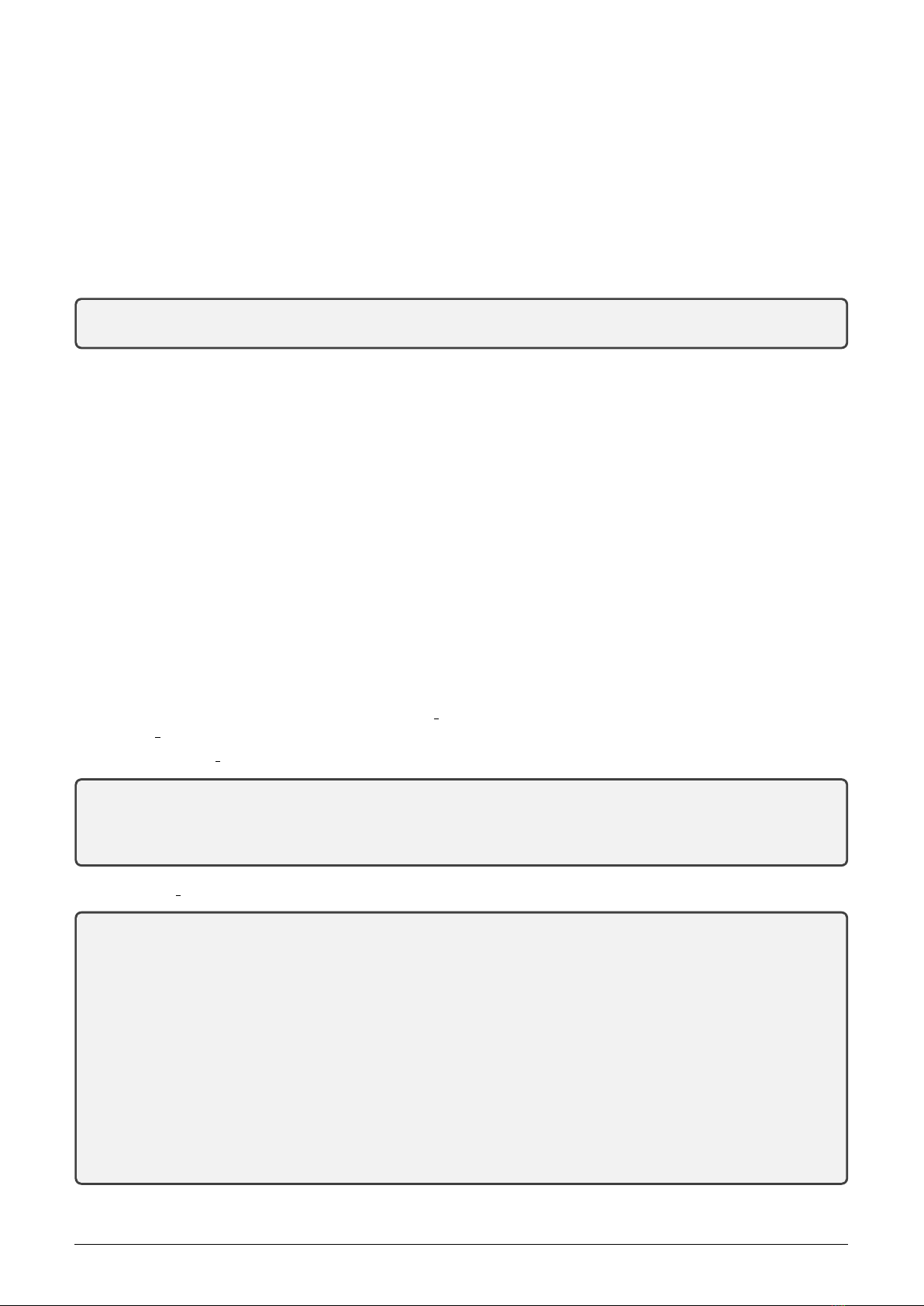
Check presence of radio signal from the neighboring modules in the ”Radar” mode by using of WEB browser.
Open any browser and enter WB169-RFE-R module’s IP-address in the form of ”http://ip address/” and start
searching. If an IP-connectivity between the computer and the module is available, website ”Radar” of the module
displays (see Figure 8), where there are the last reports from all devices broadcasting in the area of the module
radio receiving (on the same frequency 169 MHz and with the same communication mode N1 (unidirectional), or
N2 (bidirectional)).
The record of each device is displayed in a separate line where the following data can be seen:
•equipment identification
•receiving time of the last report from the equipment
WB169-RFE-R (WB169-RFG-R, WB169-RFW-R) 16

Figure 8: Example of WB169-RFE-R module ”Radar” table
•indication of radio signal quality of received message (RSSI = Received Signal Strength Indicator)
If the ”Radar” table is displayed in a sufficiently long time since the WB169-RFE-R module was putting into
operation (or since its rebooting), the table contents all the devices in the radio reach of the module including the
evaluation of the receiving quality – see Figure 8. The ”Radar” table displays only records received during last 2
hours.
When installing the local collecting Wireless M-BUS network it is recommended to put into operating the WB169-
RFE-R gateway first and the broadcasting equipment after that. Then it is possible to check the successfulness of
individual devices installation in the ”Radar” mode, including quality of the connection between broadcast devices
and the gateway.
4.10 Operation of the WB169-RFE-R module
Receiving radio messages from surrounding radio modules and forwarding of the messages to the superior system
via Internet the WB169-RFE-R module performs fully automatically. Take into consideration that the broadcasting
systems according to the Wireless M-BUS standard has no protection against interference during transmission (a
signal collision, which occurs when two modules broadcast at the same time), so that temporary loss of data from
some modules can commonly occur in case of operating of a large number of modules in one radio network. These
losses can last for several hours or days.
The greatest risks of the signal losses from surrounding radio modules are commonly caused by human activities
within the installation. It is mainly about the following risks:
•turning off the module power (e.g. circuit breaker failure or unintentional shutdown);
•malfunction of Internet connection (e.g. line drop, or change of IP-address);
•temporary or permanent shading of the antenna (e.g. due to building operations);
•mechanical damage of the module, the antenna cable or the antenna when handling things at the installation
site.
To eliminate these risks, it is recommended to pay close attention to selection of the installation site and choice of
antenna and antenna location so that to find appropriate compromise between qualities of signal and the level of
risk of mechanical damage of the module or antenna. It is necessary to carry out the installation carefully with
using of high-quality cables and mounting components. In case of loss of income data from large number (or all)
reading modules, it is recommended to contact the installation site caretaker and ask for the potential cause of the
anomaly or perform the physical check on the installation site.
WB169-RFE-R (WB169-RFG-R, WB169-RFW-R) 17

4.11 Particularities of WiFi and GSM operation of the WB169-RFE-R module
When operating the WB169-RFE-R module with local connection to the Internet via the WiFi local wireless net-
work or via the GSM/GPRS/3G mobile data network, the principle of the operation does not change, only data
transfer between the module and the superior system passes via the local wireless or mobile network. There are
following recommendations and features that are relevant for using of WiFi or GSM connection:
•only one type of local connection can be in used. When operating over LAN remove communications adapters.
When operating over the communication adapter disconnect the cable to the Ethernet and use only one
communication adapter;
•when operating over the WiFi wireless network, it is necessary to control whether the WiFi network is in
compliance with the 802.11 b/g/n standard and make settings according to the paragraph 3.3.3 ”Configuration
of WiFi communication parameters”;
•when operating over the GSM mobile network, it is possible to use GPRS, EDGE or 3G services. The adapter
does not support LTE (4G) service. During operation over the GSM mobile network it is necessary to make
settings according to the paragraph 3.3.2 ”Configuration of GSM communication parameters”;
•when operating over the GSM mobile network, it is necessary to set up with the SIM-card operator correct
setting of tariffs and services, and especially switch off the PIN-control procedure.
When displaying of ports status via the ”ifconfig” command (see paragraph 4.9) the list of ports appears as follows:
- if operation with the WiFi adapter an additional section ”wlan0” appears under ”lo” – see example:
wlan0 Link encap:Ethernet HWaddr 80:1f:02:f3:0d:1d
inet addr:172.16.16.180 Bcast:172.16.16.255 Mask:255.255.255.0
inet6 addr: fe80::821f:2ff:fef3:d1d/64 Scope:Link
inet6 addr: 2001:470:26:6b5:821f:2ff:fef3:d1d/64 Scope:Global
UP BROADCAST RUNNING MULTICAST MTU:1500 Metric:1
RX packets:90 errors:0 dropped:1 overruns:0 frame:0
TX packets:91 errors:0 dropped:1 overruns:0 carrier:0
collisions:0 txqueuelen:1000
RX bytes:11249 (10.9 KiB) TX bytes:16457 (16.0 KiB)
- if operation with the GSM adapter the new ”ppp0”section will appear under ”lo” (and - for some types of adapters
- also ”wwan0” section) - see example:
ppp0 Link encap:Point-to-Point Protocol
inet addr:10.1.0.25 P-t-P:10.64.64.64 Mask:255.255.255.255
UP POINTOPOINT RUNNING NOARP MULTICAST MTU:1500 Metric:1
RX packets:28 errors:0 dropped:0 overruns:0 frame:0
TX packets:29 errors:0 dropped:0 overruns:0 carrier:0
collisions:0 txqueuelen:3
RX bytes:160 (160.0 B) TX bytes:595 (595.0 B)
wwan0 Link encap:Ethernet HWaddr 22:92:37:5b:e4:e7
inet6 addr: fe80::2092:37ff:fe5b:e4e7/64 Scope:Link
UP BROADCAST RUNNING NOARP MULTICAST MTU:1500 Metric:1
RX packets:0 errors:0 dropped:0 overruns:0 frame:0
TX packets:1 errors:0 dropped:0 overruns:0 carrier:0
collisions:0 txqueuelen:1000
RX bytes:0 (0.0 B) TX bytes:56 (56.0 B)
While using WiFi the current IP-address displays in the second line of the section ”wlan0”, while operating of
GSM the current IP-address appears in the second line of the section ”ppp0”.
An external communication module/adapter for WiFi or GSM communication can be connected through any of
module USB ports. Simple USB adapters of ”dongle” type can be put directly on the USB port, or (if it is not
sufficient signal in the spot) connected through the extension USB cable.
It is strongly recommended to use an external GSM module with independent power supplying for GSM
communication (e.g. producer’s original WG-LTE module). Transmitting power of this module will not be limited
by peak power of USB internal source.
WB169-RFE-R (WB169-RFG-R, WB169-RFW-R) 18
This manual suits for next models
2
Table of contents
Other SOFTLINK Conference System manuals


