nestor cables NC-1000 User manual

NC-1000
INSTALLATION MANUAL
NC-1000
FIBRE OPTIC
CROSS-CONNECTION SYSTEM

Content
1. General 5
2. The products of NC-1000 system 6
3. Mounting of the frame 8
4. Earthing of the frame 8
5. Termination of outdoor cables to NC-1000 frame 9
5.1 Termination of outdoor cables to pigtail cables within the NC-1000 frame 9
5.1.1 Installation of the splice tray holder 9
5.1.2 Bringing cable to the frame 10
5.1.3 Preparation and earthing of cables 10
5.1.3.1 Stranded loose tube cables 10
5.1.3.2 Central loose tube cable 11
5.1.4 Fibre entry to the splice tray 12
5.1.5 Installation of the splice trays to the splice tray holder 13
5.1.6 Installation of NC-1000 patch panel 13
5.1.7 Bringing of pigtail cables for splicing 16
5.1.8 Construction, colour coding and the main properties of the pigtail cable 16
5.1.9 Preparing the pigtail cable for splicing 17
5.1.10 Splicing of bres 19
5.1.11 Fastening and earthing of cables 19
5.1.12 Fastening of the bre tubes 19
5.1.13 Finishing the termination 20
5.2 Termination of cables when outdoor cables are spliced to pigtail cables outside the NC-1000
frame 21
5.2.1 Bringing the outdoor cables to the splicing point 21
5.2.2 Installation of the NC-1000 patch panel 21
5.2.3 Bringing the pigtail cables from the NC-1000 frame 22
5.2.4 Finishing the termination in the NC-1000 frame 23
5.2.5 Bringing the pigtail cables to the splicing point 23
5.2.6 Construction, colour coding and the main properties of the pigtail cable 23
5.2.7 Preparing pigtail cable for splicing 23
5.2.8 Splicing of bres 24
6. The installations of the patch cords 26
6.1 Patch cord installations into the NC-1000 patch panels 27
6.2 Patch cords inside the NC-1000 frame 27
6.3 Patch cords between the NC-1000 frame and equipment racks 28
6.4 Patch cords between the NC-1000 frames 29
INSTALLATION MANUAL
NC-1000
FIBRE OPTIC
CROSS-CONNECTION SYSTEM
NC-1000 installation manual © Nestor Cables Ltd. 2011

4 5
NC-1000 - installation manual
4 5
1. General
In optical distribution frames (ODFs) optical bre cables are terminated and connected to other cables and
equipment. The number of cables coming to and leaving from an ODF may be very high depending on the
type and purpose of the ODF. Therefore it is very important that the ODF including all cable installations has
been designed, planned and installed with appropriate skill and knowledge.
NC-1000 bre optic cross-connection system is an ODF that is designed according to the most critical
requirements to reach a solution with easy installation, good functionality and high reliability. All important
aspects are taken into account regarding cable assembly, bre connections as well as addition of new
cables and modications. Modular and clear design, usage of pre-assembled patch panels and smart bre
management provide easy installation, changes, expansions and other maintenance practices during the
entire lifetime of the system.
The main features of NC-1000 are:
high bre capacity•
excellent bre management•
modular and clear design•
access from the front side•
pre-assembled patch panels•
easy to install, upgrade and maintain•
dimensions according to ETSI standard•
patch cords can be guided directly between NC-1000 frames•
bre splices may be located inside or outside of the frame•
cables can come to the frame either from bottom or from top•
NC-1000 technical data
dimensions 600 x 300 x 2200 mm or 600 x 300 x 2000 mm•
capacity for up to 960 or 864 bres (depending on the height of the frame)•
standard construction: turning inner frame, bre and cable guides in inner frame and rack, front and back •
doors and side covers
NC-1000 patch panels
connector alternatives SC/UPC, SC/APC and LC/UPC•
includes the mounting frame•
are delivered pre-assembled with the dened length of pigtail cable suitable for both indoor and outdoor •
usage
number of bres in the pigtail cable is 24 or 48•
the cable length is 5, 15, 25 and 50 m or it can be specied by the customer (A m)•
delivered with a connection card containing a coupling order and a colour coding system of the pigtail•
cable
also available as 1x16, 1x32 and 1x64 splitter modules•
INSTALLATION MANUAL
NC-1000
FIBRE OPTIC
CROSS-CONNECTION SYSTEM

6 7
NC-1000 - installation manual
6 7
2. The products of NC-1000 system
Product Short description Product No.
NC-1000 frames with accessories
NC-1000 Optical Distribution Frame,
2200 mm
ODF frame with a turnable inner frame and bre guides,
height 2200 mm. Includes doors and coverings for both
sides.
LV1109
NC-1000 Optical Distribution Frame,
2000 mm
ODF frame with a turnable inner frame and bre guides,
height 2000 mm. Includes doors and coverings for both
sides.
LV1110
NC-1000 Back cover, 2200 mm Back cover for NC-1000 frame, height 2200 mm LV1115
NC-1000 Back cover, 2000 mm Back cover for NC-1000 frame, height 2000 mm LV1116
NC-1000 Splice tray holder Holder for 18 NC-48 or LT-48 splice trays LV1117
Universal splice tray NC-48 Splice tray for 48 splices LV1075
Splice tray LT-48 Alternative splice tray for 48 bres LV1397
NC-1000 Wall mounting kit Wall mounting kit for fastening NC-1000 frame to the wall
from the top
LV1118
Pre-assembled NC-1000 patch panels with SC/UPC connectors
NC-1000 SC 24xSML 5 m NC-1000 patch panel with 24 bre pigtail cable terminated to
SC/UPC connectors, length 5 m.
LV1123
NC-1000 SC 24xSML 15 m NC-1000 patch panel with 24 bre pigtail cable terminated to
SC/UPC connectors, length 15 m.
LV1124
NC-1000 SC 24xSML 25 m NC-1000 patch panel with 24 bre pigtail cable terminated to
SC/UPC connectors, length 25 m.
LV1125
NC-1000 SC 24xSML 50 m NC-1000 patch panel with 24 bre pigtail cable terminated to
SC/UPC connectors, length 50 m.
LV1127
NC-1000 SC 24xSML A m NC-1000 patch panel with 24 bre pigtail cable terminated to
SC/UPC connectors, the length is specied by the customer.
LV1128
NC-1000 SC 48xSML 5 m NC-1000 patch panel with 48 bre pigtail cable terminated to
SC/UPC connectors, length 5 m.
LV1129
NC-1000 SC 48xSML 15 m NC-1000 patch panel with 48 bre pigtail cable terminated to
SC/UPC connectors, length 15 m.
LV1130
NC-1000 SC 48xSML 25 m NC-1000 patch panel with 48 bre pigtail cable terminated to
SC/UPC connectors, length 25 m.
LV1131
NC-1000 SC 48xSML 50 m NC-1000 patch panel with 48 bre pigtail cable terminated to
SC/UPC connectors, length 50 m.
LV1133
NC-1000 SC 48xSML A m NC-1000 patch panel with 48 bre pigtail cable terminated to
SC/UPC connectors, the length is specied by the customer.
LV1134
Pre-assembled NC-1000 patch panels with SC/APC connectors
NC-1000 SC/APC 24xSML 5 m NC-1000 patch panel with 24 bre pigtail cable terminated to
SC/APC connectors, length 5 m.
LV1174
NC-1000 SC/APC 24xSML 15 m NC-1000 patch panel with 24 bre pigtail cable terminated to
SC/APC connectors, length 15 m.
LV1175
NC-1000 SC/APC 24xSML 25 m NC-1000 patch panel with 24 bre pigtail cable terminated to
SC/APC connectors, length 25 m.
LV1176
NC-1000 SC/APC 24xSML 50 m NC-1000 patch panel with 24 bre pigtail cable terminated to
SC/APC connectors, length 50 m.
LV1178
NC-1000 SC/APC 24xSML A m NC-1000 patch panel with 24 bre pigtail cable terminated to
SC/APC connectors, the length is specied by the customer.
LV1179
NC-1000 SC/APC 48xSML 5 m NC-1000 patch panel with 48 bre pigtail cable terminated to
SC/APC connectors, length 5 m.
LV1180
NC-1000 SC/APC 48xSML 15 m NC-1000 patch panel with 48 bre pigtail cable terminated to
SC/APC connectors, length 15 m.
LV1181
NC-1000 SC/APC 48xSML 25 m NC-1000 patch panel with 48 bre pigtail cable terminated to
SC/APC connectors, length 25 m.
LV1182
NC-1000 SC/APC 48xSML 50 m NC-1000 patch panel with 48 bre pigtail cable terminated to
SC/APC connectors, length 50 m.
LV1184
NC-1000 SC/APC 48xSML A m NC-1000 patch panel with 48 bre pigtail cable terminated to
SC/APC connectors, the length is specied by the customer.
LV1185
Product Short description Product No.
Pre-assembled NC-1000 patch panels with LC/UPC connectors
NC-1000 LC 24xSML 5 m NC-1000 patch panel with 24 bre pigtail cable terminated to
LC/UPC connectors, length 5 m.
LV1135
NC-1000 LC 24xSML 15 m NC-1000 patch panel with 24 bre pigtail cable terminated to
LC/UPC connectors, length 15 m.
LV1136
NC-1000 LC 24xSML 25 m NC-1000 patch panel with 24 bre pigtail cable terminated to
LC/UPC connectors, length 25 m.
LV1137
NC-1000 LC 24xSML 50 m NC-1000 patch panel with 24 bre pigtail cable terminated to
LC/UPC connectors, length 50 m.
LV1139
NC-1000 LC 24xSML A m NC-1000 patch panel with 24 bre pigtail cable terminated to
LC/UPC connectors, the length is specied by the customer.
LV1140
NC-1000 LC 48xSML 5 m NC-1000 patch panel with 48 bre pigtail cable terminated to
LC/UPC connectors, length 5 m.
LV1141
NC-1000 LC 48xSML 15 m NC-1000 patch panel with 48 bre pigtail cable terminated to
LC/UPC connectors, length 15 m.
LV1142
NC-1000 LC 48xSML 25 m NC-1000 patch panel with 48 bre pigtail cable terminated to
LC/UPC connectors, length 25 m.
LV1143
NC-1000 LC 48xSML 50 m NC-1000 patch panel with 48 bre pigtail cable terminated to
LC/UPC connectors, length 50 m.
LV1145
NC-1000 LC 48xSML A m NC-1000 patch panel with 48 bre pigtail cable terminated to
LC/UPC connectors, the length is specied by the customer.
LV1146
Indoor/outdoor cables for pigtail cable kits with a customized length
FZOMSU-SD Mini 2x12xSML 24 bre indoor/outdoor cable, od. 7,5 mm L10392
FZOMSU-SD Mini 4x12xSML 48 bre indoor/outdoor cable, od. 7,5 mm L10393
NC-1000 splitter modules
NC-1000 splitter 1x16 SC/APC Splitter module 1x16 with SC/APC connectors LV1186
NC-1000 splitter 1x32 SC/APC Splitter module 1x32 with SC/APC connectors LV1187
NC-1000 splitter 1x64 SC/APC Splitter module 1x64 with SC/APC connectors LV1240
8 9
NC-1000 - installation manual
8 9
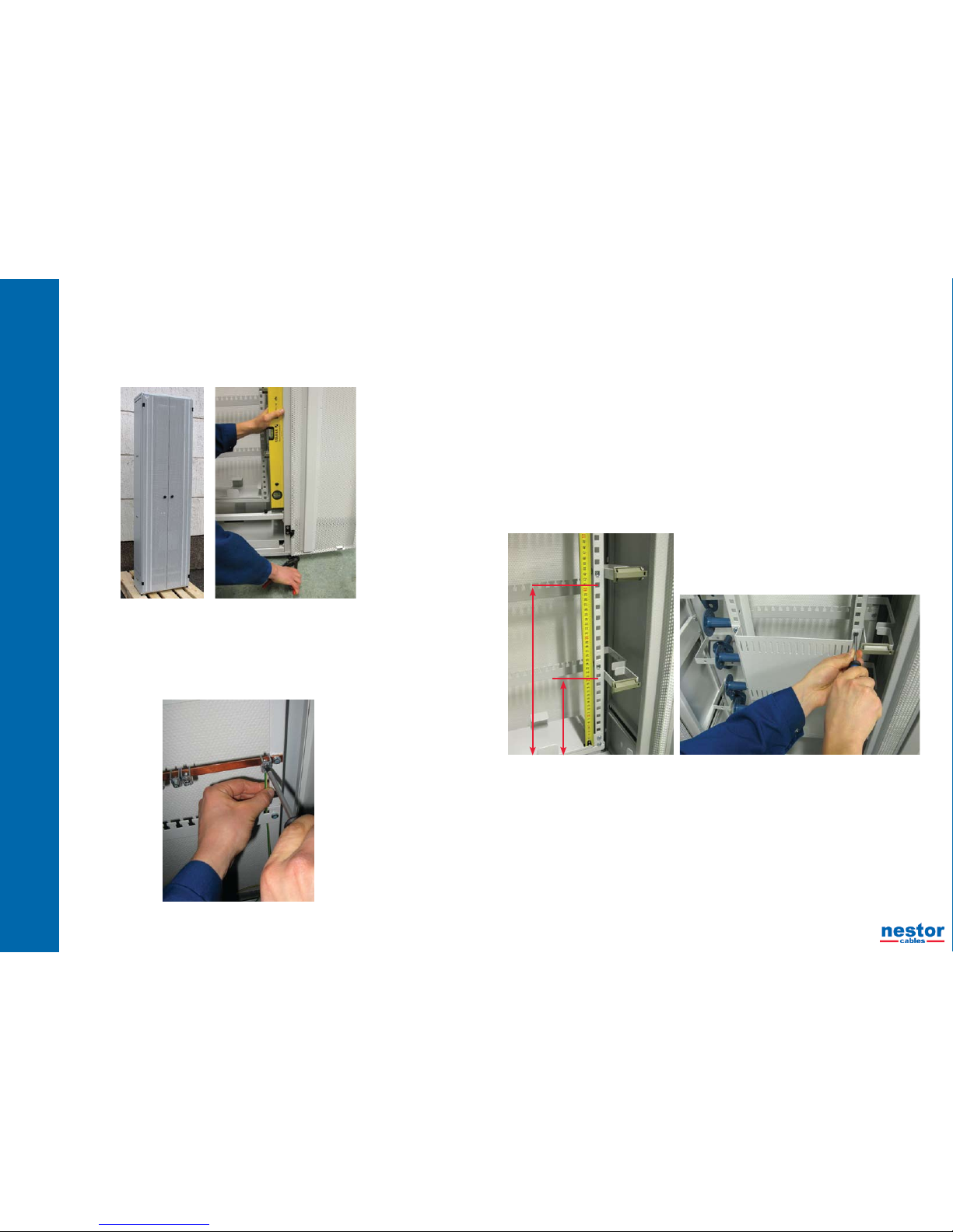
3. Mounting of the frame
NC-1000 frames are delivered separately protected with their own transportation pallet. In the
installation site the frame is shifted to its place and fastened to the oor. Before fastening the
frame shall be adjusted directly from its adjusting feets. If necessary, the frame can be also
fastened to the wall from the top with an optional wall mounting kit.
4. Earthing of the frame
If outdoor cables including metallic elements are brought to the frame, the frame shall earthed.
Make the earthing by connecting the frame to the equipotential or earthing terminal of the
equipment room by using min. 16 mm2 copper wire. Adjust the earthing bar of the frame to the
suitable height and connect the copper wire to the bar.
5. Termination of outdoor cables to NC-1000 frame
There are two principle ways of outdoor cable termination:
Outdoor cables are jointed to pigtail cables within the NC-1000 frame.1.
Outdoor cables are jointed to pigtail cables outside the NC-1000 frame within a joint closure or a splice2.
cabinet.
These termination methods are handled separately in the following chapters.
5.1 Termination of outdoor cables to pigtail cables within the NC-1000 frame
5.1.1 Installation of the splice tray holder
Take the splice tray holder with its mounting accessories from its package and turn it in the right way for•
mounting to the inner frame.
Install the basket nuts of the splice tray holder to the followig mounting places of the inner frame:•
upper nuts: 43 cm from the bottom of the inner fame
lower nuts: 23 cm from the bottom of the inner fame
Fix the splice tray holder with its screws to the inner frame.•
43 cm
23 cm

10 11
NC-1000 - installation manual
10 11
5.1.2 Bringing cable to the frame
Either the top entry or the bottom entry can be used. Cables are brought to the frame outside
of the back side where they are earthed if necessary and from where the bres are brought to
the inner frame and to the splice trays in their protection tubes.
It is worth of noting that the cables are not xed permanently to the frame until they have been
spliced.
Cables are brought to the frame as follows:
Release the locking of the inner frame from its bottom and turn it out as much as it goes.•
Draw the cable ends through the frame below its lowes xing plate. •
Draw the cable ends enough out from the frame over their stripping lenght. The stripping•
length is about 250 cm.
Measure about 250 cm stripping lengths of the cables starting from the sheath removal •
points and cut away the extra lenghts.
5.1.3 Preparation and earthing of cables
Remove the cable sheaths starting from the sheath removal marks.•
Prepare and earth the cables according to the instructions of the cable supplier.•
Two examples are described in the chapters 4.1.3.1 and 4.1.3.2. It should be noted that•
these are only examples. In every case the instructions of the cable supplier shall be
carefully followed.
5.1.3.1 Stranded loose tube cables
Cut the cable sheath from the sheath removal point marked before.•
Remove the cable sheath about 10 cm from the cable end and nd the rip cords.•
Split the cable sheath with rip cords to the sheath removal point and about 30 mm over it.•
Cut the parts of the cable sheath from the sheath removal point.•
Remove all protective layers over the bre tubes.•
Separate the bre tubes and the possible llers from each other.•
Cut the central element and the possible llers at the point where the sheath has been cut. Note, if the •
cable has metallic central element cut it to the length of about 20 cm.
Straighten the bre tubes by using a hot air blower or hot water. If you use a hot air blower, be careful •
that the bre tubes dont’t get too hot.
Connect the connector of the earthing conductor to the possible aluminium laminate or corrugated steel•
tape. Protect the connection point with an insulating tape.
5.1.3.2 Central loose tube cable
Expose the strength elements on both sides of the cable and turn them up to the sheath removal point•
marked before. Cut them to the length of about 20 cm and bend them on both sides.
In the case of a cable with aluminium laminate or corrugated steel tape remove the sheath and other•
protective layers up o the distance of 50 mm from the sheath removal point. Remove the cable sheath
in several parts.
In the case of non-metallic cable remove the sheath and protective layers up to the sheath removal•
point. Remove the sheath in several parts.
Remove the sheath from the possible aluminium laminate or corrugated steel tape with a hot air blower•
and pliers.
Use e.g. a steel brush or a knife to remove also the possible plastic coating from the laminate or steel•
tape in order to ensure the electrical contact for earthing.
In the case of metallic strength elemens turn them to the same side of the cable and then at the•
distance of about 30 mm from the cable towards the cable end. Try to get them as straigth as possible
and also near each other that they can be easily guided to the earthing connector. Cut them to the
same length as the aluminium laminate or corrugated steel tape.
Cut the central tube at the distance of 30 mm from the aluminium laminate or steel tape and in a case of•
non-metallic cable at the distance of 30 mm from the cable sheath. Cut the central tube by making rst
a scratch around the tube and then bending the tube carefully at the both sides until it breaks.
Take a hold from the bres with ngers and pull the central tube away.•
12 13
NC-1000 - installation manual
12 13
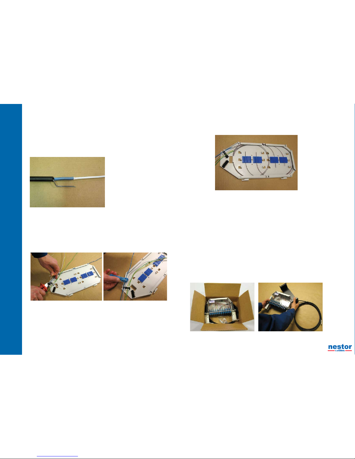
Clean the bres from the lling compound.•
Push the fan-out part of the installation kit (accessory) over the central tube and at the•
same time guide the bre bundles along their own slots of the fan-out part.
Fasten the fan-out part with the clamp to the end of the central tube. If the fastening is not•
tight, use the small adjusting parts of the kit under the clamp.
Draw the bundled bres into the protection tubes of the installation kit by using the pulling •
wire included the kit. The minimum length of the tubes is 110 cm.
Push the protection tubes to the slots of the fan-out part and guide the bres at the same •
time directly from the central tube to the protection tubes.
Mark the ends of the protection tubes with numbers 1,2,…•
5.1.4 Fibre entry to the splice tray
Remove the cover of the splice tray•
Measure the bre lenghts to the splice tray. If using Nestor NC-48 splice tray the bre •
lengths shall be about 120 cm.
Bring the ends of the bre tubes to the left side of the splice tray (seen from the top) and •
put them parallel so that the outermost tube is the rst and innermost tube the last tube.
Fix the tubes with nylon ties.•
If you are terminating stranded loose tube cable cut the tubes about 25 mm from the xing •
point and clean the tubes from the lling compound.
Loop the bres to the splice tray. Loop each bre bundle one full turn on the tray and take •
each bre bundle to its own splice holder from the left side Cut away the extra lengths of
bres.
If you are using Nestor NC-48 splice tray, loop the bres going to the two uppermost splice holders one •
full turn around the tray and then to their splice holders from the left. The bres going to two lowest
splice holders loop bres rst to other side of the tray from the halfway of the tray, then one full turn
around the tray and nally to their own splice holders from the right, see the picture below.
Make the appropriate markings on the splice tray. •
Reattach the cover to the splice tray.•
5.1.5 Installation of the splice trays to the splice tray holder
Draw the cable backwards to the back side of the frame so much that the cable sheath is outside of the•
frame.
Fix the cable temporarily to the frame.•
Install the splice tray into its appropriate position for waiting the splicing process.•
Guide the bre tubes below the splice trays on the hinge side of the inner frame to the back of the •
frame.
The bre tubes shall be positioned considering the following:•
Bending radius of bres○
Movement of the inner frame○
Possibility to remove each splice tray separately from the splice tray holder○
5.1.6 Installation of NC-1000 patch panel
Open the panel package and lift the panel out from the package with its pigtail cable.•
Take the basket nuts from the accessory kit and mount them to the right places of the inner frame.•
Install the rst panel of the frame into the highest place of the inner frame and the next panels under the •
earlier panels.
Pull the panel frame out from the panel and fasten it to the inner frame from its lowest xing holes.•

14 15
NC-1000 - installation manual
14 15
Open the pigtail cable loop and straighten it.•
Mark the end of the pigtail cable by the identication number of the panel.•
Push the pigtail cable through the panel frame and guide it to the management hooks in•
the right side of the inner frame. Do not x the cable to the loops – leave it as loose as
possible.
Push the panels separately to their places and lock them with nger screws.•

16 17
NC-1000 - installation manual
16 17
The colour coding system of the pigtail cable is as follows:•
Fibre tubes:○
- 24 bre cable: blue, red
- 48 bre cable: blue, white, yellow, red
Fibres:○
No. 1 blue No. 7 red
No. 2 orange No. 8 black
No. 3 green No. 9 yellow
No. 4 brown No. 10 violet
No. 5 grey No. 11 pink
No. 6 white No. 12 aqua (turquoise)
The main installation properties of the pigtail cable are as follows:•
Bending radius: min. 120 mm○
Pulling force: 1000 N○
Temperature range○
- Installation: min. -15 - +70˚C
- Operation: -40 - +70˚C
5.1.9 Preparing the pigtail cable for splicing
Remove the pigtail cable from the management hooks of the inner frame.•
Cut the sheath at the point of the cutting mark.•
Remove the sheath at the length of about 10 cm from the cable end and nd the rip cord.•
Split the cable sheath by using the rip cord and remove the sheath.•
Cut all the binding yarns, tapes, llers and the central element at the point where the cable sheath was •
cut.
Fasten the end of the cable sheath with nylon ties to the side of the splice tray which is opposite to the•
side where the bre tubes of the outdoor cable are fastened.
Cut the bre tubes at the distance of about 10 cm from the point where the sheath was cut and clean •
the bres from the lling compound.
Note. Try rst the stripping of the bre tubes before the actual work to make sure that you have a ○
suitable stripping tool and the tool has the right adjustments. A wrong tool or a wrong adjustments
of the tool can cause damages or even cut the bres.
5.1.7 Bringing of pigtail cables for splicing
Bring the pigtail cable to its splice tray loosely below the splice tray and from the front side•
(seen from the front).
Make a cutting marks on the cable to such lengths that the sheath length on the splice tray •
is about 30 mm and the bre length is at least 110 cm. If using Nestor NC-48 splice tray
the bre lengths shall be about 120 cm.
Cut away the extra length from the pigtail cable.•
Remove the splice tray from the splice tray holder and set it on the splicing table.•
5.1.8 Construction, colour coding and the main properties of the pigtail cable
The construction and materials of the pigtail cable is described in the picture below.•
Loose buffer tube with 12 colour coded singlemode
bres and lling compound.
Dry cable core.
Central element (FRP)
Filler
Swellable tape
Rip cord
Black UV-resistant outer jacket, FRNC,
od. 7,5 mm
18 19
NC-1000 - installation manual
18 19
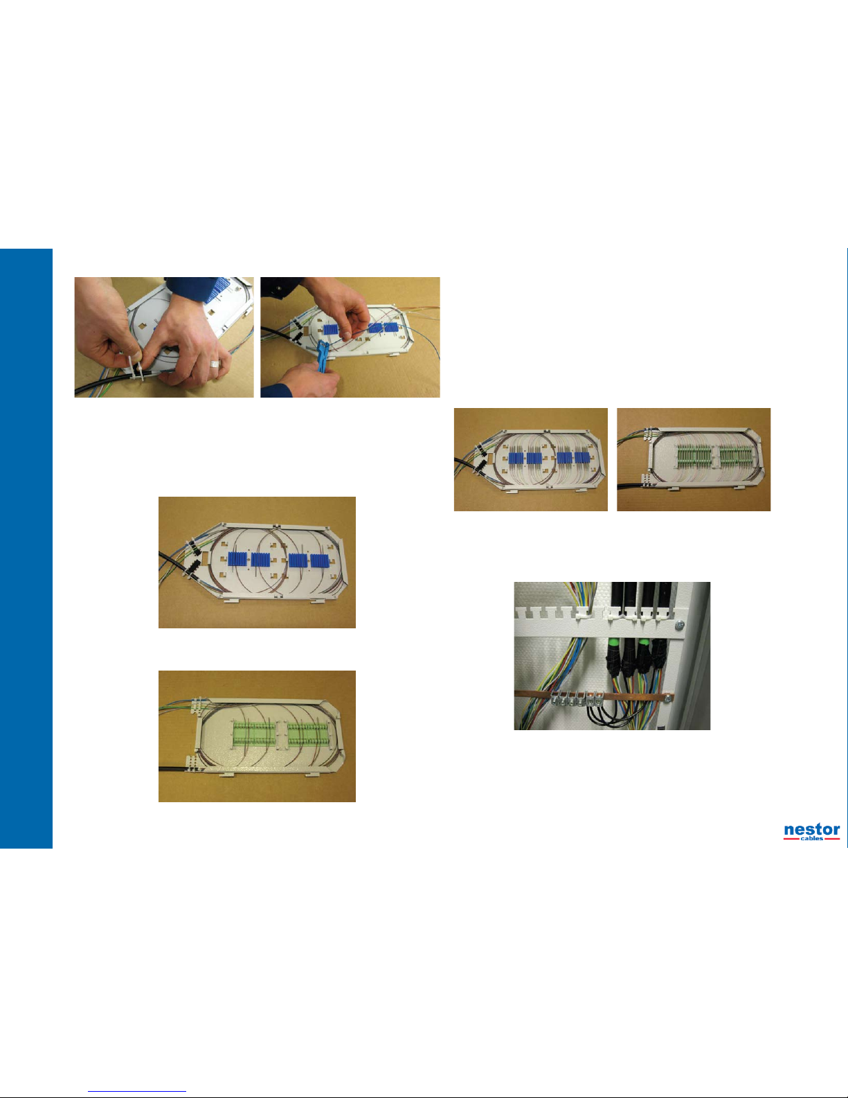
Loop the bres on the splice tray. Loop each bre bundle one full turn on the tray and take •
each bre bundle to its own splice holder from the right side. Cut away the extra lengths of
bres.
If you are using Nestor NC-48 splice tray, loop the bres going to the two uppermost splice •
holders one full turn around the tray and then to their splice holders from the right. The
bres going to two lowest splice holders loop rst to other side of the tray from the halfway
of the tray, then one full turn around the tray and nally to their own splice holders from the
left, see the picture below.
In the following picture the bres have been prepared for splicing by using an alternative •
splice tray LT-48.
5.1.10 Splicing of bres
Take the bre bundles out from the splice holders and place them on both sides of the splice tray in •
their order.
Splice the bres of the outdoor cable to the bres of the pigtail cables bundle by bundle with a fusion •
splicer.
Loop the spliced bres on the splice tray and place the bre protection sleeves to the holders according •
to the bre order. Take care in looping the bres that you don’t leave the bres under their minimum
bending radius (min. 40 mm).
When all the bres have been spliced check still that the installation of all the bres on splice tray has •
been made properly. In the following pictures there are examples of the splice trays after all bres have
been spliced.
Fasten the cover of the splice tray.•
Mount the splice tray into its position in the splice tray holder.•
5.1.11 Fastening and earthing of cables
Place the outdoor cables after splicing in the backside of the frame to their right positions and fasten•
them to the xing plates with nylon ties. The fastening and positioning should take into account the
possibility of adding new cables in the future.
Connect the metallic elements of the cables to the earthing bar of the frame.•
5.1.12 Fastening of the bre tubes
Guide and manage the bre tubes leaving the splice trays from the hinge side of the inner frame to the •
back of the frame.
Loop and bundle the bre tubes and fasten the bundles to the xing plates in the back of the frame. •
As fastening the tubes note the movement of the inner frame. E.g do not fasten the tubes to the lowest•
xing plate because at this place the tubes shall have a possibility for slight movements.
If necessary the bre tubes at the back side of the frame can be protected with e.g. a spiral type •
protection tube.

20 21
NC-1000 - installation manual
20 21
5.1.13 Finishing the termination
Close the inner frame to its normal position and x it with the lock that is on the bottom of •
the frame.
Check still that the bre tubes run from splice trays to the back of the frame in a well •
managed way and are not subject to pressure, sharp bendings or any other risks.
5.2 Termination of cables when outdoor cables are spliced to pigtail cables outside the NC-1000
frame
Outdoor cables can be spliced to pigtail cables outside of the NC-1000 frame in a splice cabinet or joint
closure that can be inside or outside of the building. If the splices are outdoor , the pigtail cables have to be
brought to these splice points in duct pipes, not directly in the ground because the construction of the pigtail
cables does not withstand the direct installation in the ground.
In this chapter it is handled more exactly only the points that differ from the working steps described in the
chapter 4.1.
5.2.1 Bringing the outdoor cables to the splicing point
Bring the outdoor cables to the point (frame, rack, cabinet or closure) where the splicing will be made.•
Measure the stripping lengths of the cables and cut away the extra lengths. Note that the bre lengths •
on the splice trays shall be at least 110 cm. If using Nestor NC-48 splice tray the bre lengths shall be
about 120 cm.
Prepare the cables for splicing as described in the chapter 4.1.3.•
Fasten and earth the cables.•
Bring the bres to the splice trays as described in the chapter 4.1.4. In the following picture bres of the •
outdoor cable have been brought to Nestor NC-48 splice tray.
Make the appropriate markings on the splice tray.•
Place the splice trays to their positions for waiting the splicing process.•
5.2.2 Installation of the NC-1000 patch panel
Release the locking of the inner frame from its bottom and turn it out as much as it goes.•
If the pigtail lengths are not long (less than 25 m) you can do directly the working steps as described in•
the chapter 4.1.6.
Note. If the pigtail cables are long or rather long (over 15 m) they are quite troublesome to straigthen or•
handle near the frame and especially in the case of many pigtail cables. In these cases the installation
of the panels can be made on the alternative way as follows:
Loosen the loops of the pigtail cables near the panels about 2 m.○
Take the cable loops one by one under the lowest xing plate to the back side of the frame and ○
bring the panel through the inner frame to the front side of the frame.
Lift the panel near its right position to the front of the inner frame and at the same time lift the panel○
frame to its position and fasten it to the frame from its lower xing holes.
Push the panel to its position and lock it with two nger screws.○
22 23
NC-1000 - installation manual
22 23
5.2.3 Bringing the pigtail cables from the NC-1000 frame
Guide the ends of the pigtail cables from the lower part of the inner frame and bring them•
outside the frame below the lowest xing plate and on the hinge side of the inner frame.
Note. Do not fasten the cables to the lowest xing plate because at this place the cables •
shall have a possibility for slight movements.
If the pigtail cables are routed from the frame downwards under the oor, they are looped •
behind the frame in such a away that the cables are rst brought upwards and then
downwards on the right side of the frame (seen from the front) and towards the oor.
Cables are bundled and fastened to the xing plates of the frame.
If the pigtail cables are routed from the frame upwards e.g. to the cable shelf, make rst •
a small loop to the left (seen from the front) and fasten cables to the xing plates of the
frame.
As routing and fastening the pigtail cables note the bending radius of the cables and the•
movement of the inner frame.
5.2.4 Finishing the termination in the NC-1000 frame
Close the inner frame to its normal position and x it with the lock that is on the bottom of the frame.•
Check still that the pigtail cables run from the inner frame to the back of the frame in a well managed•
way and are not subject to pressure, sharp bendings or any other risks.
5.2.5 Bringing the pigtail cables to the splicing point
Bring the pigtail cables to the splice cabinet or joint closure.•
Measure the pigtail cables so that the sheath length on the splice tray is about 30 mm and the bre •
length is at least 110 cm. If using Nestor NC-48 splice tray the bre lengths shall be about 120 cm.
Make the cutting marks on the cables and cut away the extra lengths•
Remove the rst splice tray from its holder and set it on the splicing table.•
5.2.6 Construction, colour coding and the main properties of the pigtail cable
See the chapter 4.1.8•
5.2.7 Preparing pigtail cable for splicing
See the chapter 4.1.9•
24 25
NC-1000 - installation manual
24 25
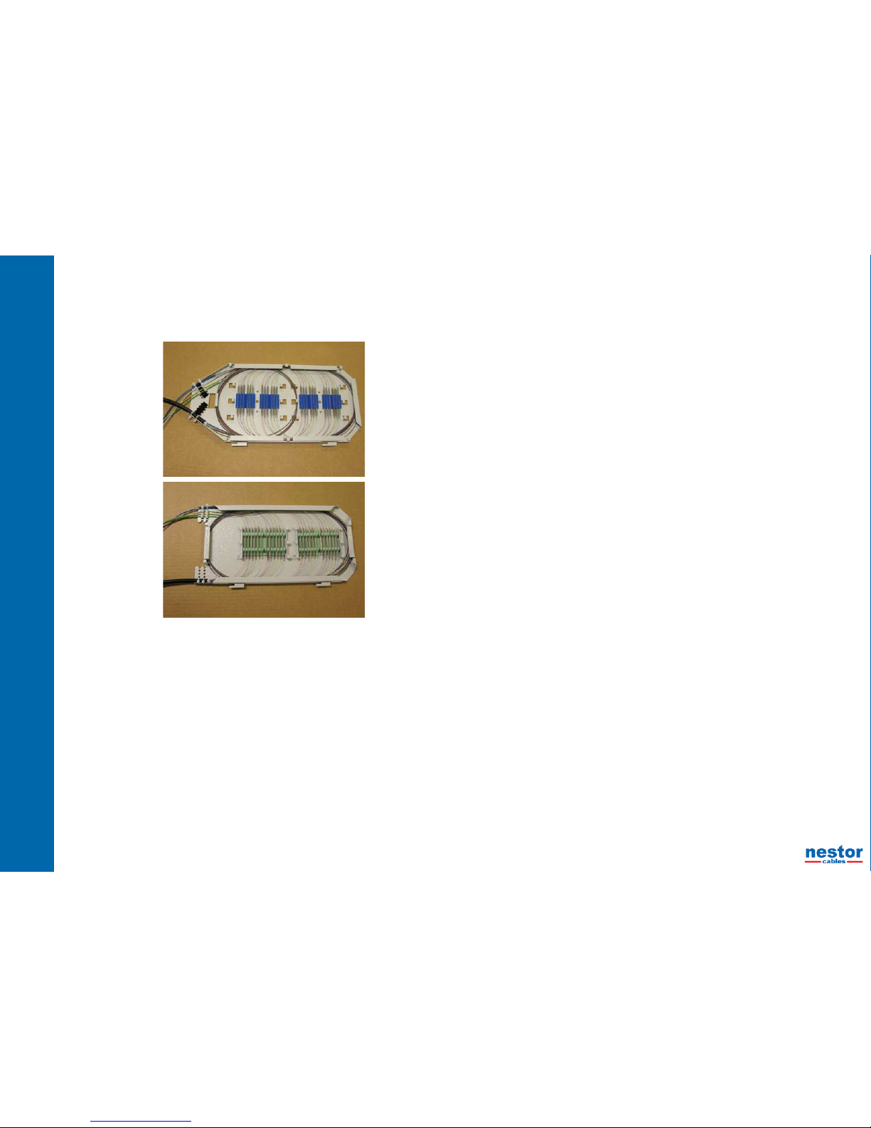
5.2.8 Splicing of bres
See the chapter 4.1.10•
In the pictures below the bres of the outdoor cables have been spliced to the bres of the •
pigtail cables as using Nestor NC-48 splice tray, upper picture or alternative splice tray LT-
48, lower picture.

26 27
NC-1000 - installation manual
26 27
6. The installations of the patch cords
The following installation cases are described in the next chapters:
Patch cord installations into the NC-1000 patch panels•
Patch cord installations inside the NC-1000 frame between patch panels•
Patch cord installations between the NC-1000 frame and equipment racks•
Patch cord installations between the NC-1000 frames•
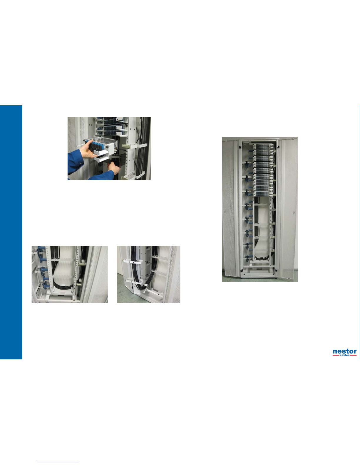
6.1 Patch cord installations into the NC-1000 patch panels
Bring the patch cords directly to the patch panels without threading through any bre guides and •
connect them to the adapters after cleaning (using e.g. a cleaning cassette)
After connections guide the patch cords to the right or left to the cabling space of the frame according to•
the instructions in the chapters 5.2 and 5.3.
If you have to make or change connections in fully loaded patch panels, the handling of the connectors•
and specially disconnecting of the connectors can be quite difcult. For these cases Nestor Cables
can deliver special tools for handling very common SC type connectors, product code LV1256, see
pictures below.
6.2 Patch cords inside the NC-1000 frame
Take the patch cords to the right side of the turnable inner frame.•
Guide the patch cords through the right side guides of the panels and to the front part of the cabling•
space of the inner frame.
Bring the patch cord loops in the cabling space of the inner frame around the nearest guide to keep•
them in order.

28 29
NC-1000 - installation manual
28 29
If the patch cords are too long to be stored in the cabling space of the inner frame, guide•
all extra patch cord lenghts to the cabling space on the left side of the frame and further to
the bottom of the frame, if needed. The bottom of the frame works as a storage for patch
cords.
6.3 Patch cords between the NC-1000 frame and equipment racks
Bring the patch cords to the left side of the patch panels and to the cabling space of the•
frame.
Bring the patch cords rst in the cabling space of the frame downwards at the right side of •
the guides in the back of the frame. Turn the patch cords to the left side of cabling space
and further upwards along the back of the frame and through the opening at the top of the
frame. The appropriate turning point depends on the lengths of the patch cords.
Guide all extra patch cord lengths to the cabling space on the left side of the frame and further to the•
bottom of the frame, if needed. The bottom of the frame works as a storage for patch cords, see the
earlier chapter.
Take care of the appropriate protection of the cabling between racks. If the patch cords are thin single•
bre cords or zipcords, it is recommendable to place them to e.g. bre optic shelfs that have been
developed for these purposes.
6.4 Patch cords between the NC-1000 frames
Patch cords can be brought from one frame to another directly through the basements of the NC-1000•
frames that work also as cabling conduits between the frames.
If the NC-1000 frames are placed side by side, the small hatches between the frames shall be removed•
before fastening the new frame against the older one.
When the NC-1000 frames are side by side, patch cords can be brought from one frame to another•
through those openings between the frames.
If the NC-1000 frames are situated back to back, patch cords can be brought from one frame to another•
directly through the openings of the bottom plates in the NC-1000 frames.

30 31
NC-1000 - installation manual
30 31
NOTES
__________________________________________________________________________
__________________________________________________________________________
__________________________________________________________________________
__________________________________________________________________________
__________________________________________________________________________
__________________________________________________________________________
__________________________________________________________________________
__________________________________________________________________________
__________________________________________________________________________
__________________________________________________________________________
__________________________________________________________________________
__________________________________________________________________________
__________________________________________________________________________
__________________________________________________________________________
__________________________________________________________________________
__________________________________________________________________________
__________________________________________________________________________
__________________________________________________________________________
__________________________________________________________________________
__________________________________________________________________________
__________________________________________________________________________
__________________________________________________________________________
__________________________________________________________________________
__________________________________________________________________________
__________________________________________________________________________
__________________________________________________________________________
__________________________________________________________________________
__________________________________________________________________________
__________________________________________________________________________
_____________________________________________________________________________________
_____________________________________________________________________________________
_____________________________________________________________________________________
_____________________________________________________________________________________
_____________________________________________________________________________________
_____________________________________________________________________________________
_____________________________________________________________________________________
_____________________________________________________________________________________
_____________________________________________________________________________________
_____________________________________________________________________________________
_____________________________________________________________________________________
_____________________________________________________________________________________
_____________________________________________________________________________________
_____________________________________________________________________________________
_____________________________________________________________________________________
_____________________________________________________________________________________
_____________________________________________________________________________________
_____________________________________________________________________________________
_____________________________________________________________________________________
_____________________________________________________________________________________
_____________________________________________________________________________________
_____________________________________________________________________________________
_____________________________________________________________________________________
_____________________________________________________________________________________
_____________________________________________________________________________________
_____________________________________________________________________________________
_____________________________________________________________________________________
_____________________________________________________________________________________
____________________________________________________________________________________ .

www.nestorcables.
info@nestorcables.
etunimi.sukunimi@nestorcables.
Sales and marketing Factory
Miestentie 1 P.O. Box 276
FI-02150 Espoo FI-90101 OULU
Table of contents
Other nestor cables Cables And Connectors manuals


