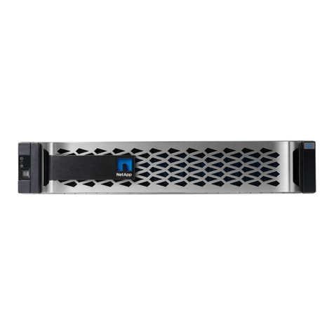
NetApp EF Series Manual

1 | Prepare for Installation
Create an account and register your hardware at mysupport.netapp.com.
Inventory cables and make note of the quantity.
Prepare for Installation Install Hardware Connect the Cables Complete System Setup
and Configuration 4321
EF-Series EF600
Installation and Setup Instructions
210-06791+A0
You provide
Resources
In the box Shelf with drives installed
(Bezel and end caps
packaged separately)
A supported browser
for the management
software
I/O cables
if ordered
Ethernet cables
if ordered
Power cables
two for each shelf
if ordered
Phillips #2 screwdriver,
flashlight, and ESD strap
2U
2U rack space
Rackmount hardware
A standard 19 in. (48.30 cm)
rack to fit 2U shelves of the
following dimensions:
Max Weight: 60.5 lb (27.4 kg)
Depth: 19.0 in. (48.3 cm)
Width: 17.6 in. (44.7 cm)
Height: 3.34 in. (8.48 cm)
Shelf: 24-drive
Hardware Universe
hwu.netapp.com
NetApp Interoperability Matrix
mysupport.netapp.com/matrix
Cabling Guide
docs.netapp.com/ess-11/topic/
com.netapp.doc.e-hw-cabling/home.html
E-Series Documentation Center
http://docs.netapp.com/ess-11/index.jsp
NetApp Inc.
1395 Crossman Ave.
Sunnyvale CA, 94089 U.S.A.
Telephone: +1 (408) 822-6000
Fax: +1 (408) 822-4501
Support Telephone: +1 (888) 463-8277
Comments: doccomments@netapp.com
© 2019 NetApp, Inc. All Rights Reserved.
NETAPP, the NETAPP logo, and the marks listed
at www.netapp.com/TM are trademarks of
NetApp, Inc. Other company and product names
may be trademarks of their respective owners.

2 | Install Hardware
Before you begin
Unpack the hardware
Install the rails
Install the shelf
When handling hardware, wear an ESD wristband or take appropriate anti-static precautions
To prevent the equipment from toppling over, install the hardware from
the bottom of the rack or cabinet to the top.
For online instructions for installing SuperRails refer to
the AFF and FAS System Documentation Center.
You have registered your hardware at mysupport.netapp.com
Unpack the contents and take inventory of the contained hardware against the packing slip.
If instructions were included with your rack-mounting hardware, refer to them
for detailed information on how to install the rails.
For more information, see the instructions for
the rack-mounting hardware.
Caution: Team-lift with two people
when installing the shelf.
If you are installing multiple shelves, begin installing from the bottom to
the top of the cabinet. Position the back of the shelf onto the rails.
Supporting the shelf from the bottom, slide it into the cabinet.
Before proceeding, read through all the instructions.
You have prepared a flat, static-free work area.
You have taken anti-static precautions.
2
3
4
Secure the shelf
5
Align the bezel with the shelf and snap into place.
Install the bezel
6

3 | Connect the Cables
Plug in the power cables, one to each controller
Connect the two power cables, one from each controller,
to two separate power distribution units (PDUs) in
the rack or cabinet
2
When handling hardware, wear an ESD wristband or take appropriate anti-static precautions.
Accessing an EF600 controller canister from the shelf can be blocked by third-party PDUs.
Do not use power outlets directly behind the controller canister.
Fans will be very loud when powering on.
The controller will boot automatically. The LEDs will flash on, and the fans will spin-up to indicate that the controller is powering on.
Allow the controller to boot for five minutes before completing the storage system setup and configuration.
Cable the data hosts
Cable the storage system according to your network topology:
A. Direct-attach topology
Connect each host adapter directly
to the host ports on the controllers.
B. Fabric topology
Connect each host adapter directly to the switch.
Connect each switch directly to the host
ports on the controllers.
3
OPTION OPTION

Your DHCP server is configured to associate an IP address, subnet mask, and gateway address as a permanent
lease for each controller.
You have obtained the assigned IP addresses you will use to connect to the storage system from your network administrator.
Step 1 – Connect an Ethernet cable to each controller’s management port, and connect the other end to your network.
(See the graphic identifying the management port.)
Step 2 – Open a browser and connect to the storage system using one of the IP addresses provided to you by your
network administrator.
OPTION A Management port configuration with DHCP
Before you begin
You use the same IP addresses that you used to configure your
management ports to access SANtricity System Manager.
Before you begin
You have configured your management ports and have verified and
recorded your password and IP addresses.
Step 1 – Connect your controller to a web browser and use SANtricity System Manager
for managing your EF600 series storage system.
After installing the hardware
2
4 | Complete System Setup and Configuration
OPTION B Management port configuration with
static IP addresses
Before you begin
You have obtained the controllers’ IP address, subnet mask, gateway address, DNS, and NTP server information
from your network administrator.
You have ensured that the laptop you are using is not receiving network configuration from a DHCP server.
Step 1 – Using an Ethernet cable, connect controller A’s management port to the Ethernet port on a laptop.
Step 2 – Open a browser and use the default IP address (169.254.128.101) to establish a connection to the
controller. The controller sends back a self-signed certificate. The browser informs you that the
connection is not secure.
If you are unable to establish a connection, verify that you are not receiving network configuration from a DHCP server.
Because you reset the IP address, System Manager loses connection to the controller. This is expected.
Step 4 – Set the storage system’s password to login.
Step 3 – Follow the browser’s instructions to proceed and launch SANtricity System Manager.
Step 5 – Use the network settings provided by your network administrator in the Configure Network Settings wizard
to configure controller A’s network settings, and then select Finish.
Step 6 – Disconnect your laptop from the storage system, and connect the management port on controller A to your network.
Step 7 – Open a browser on a computer connected to your network, and enter controller A’s newly configured IP address.
Attention: If you lose the connection to controller A, you can connect an ethernet cable to controller B
to reestablish connection to controller A through controller B (169.254.128.102).
Step 8 – Log in using the password you set previously. The Configure Network Settings wizard will appear.
Step 9 – Use the network settings provided by your network administrator in the Configure Network Settings wizard
to configure controller B’s network settings, and then select Finish.
Step 10 – Connect controller B to your network.
Step 11 – Validate controller B’s network settings by entering controller B’s newly configured IP address in a browser.
Attention: If you lose the connection to controller B, you can use your previously validated connection to controller A
to reestablish connection to controller B through controller A.
Connect and configure the management connection
1
Identifying the management port
Controller A is the upper controller canister, and controller B is the lower controller canister.
Other manuals for EF Series
1
This manual suits for next models
1
Table of contents
Other NetApp Disk Array System manuals

NetApp
NetApp AFF A900 User manual

NetApp
NetApp AFF A900 User manual

NetApp
NetApp E2760 User manual

NetApp
NetApp E Series User manual

NetApp
NetApp FAS User manual

NetApp
NetApp AFF User manual

NetApp
NetApp AFF A220 User manual

NetApp
NetApp ASA A900 User manual

NetApp
NetApp AFF A300 User manual

NetApp
NetApp AFF A700 Manual