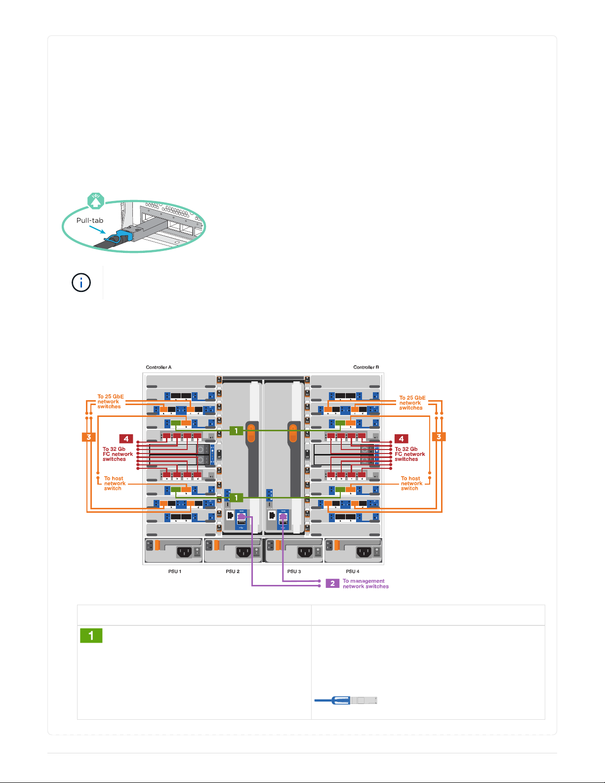
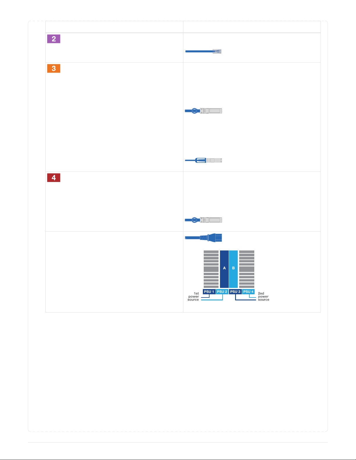
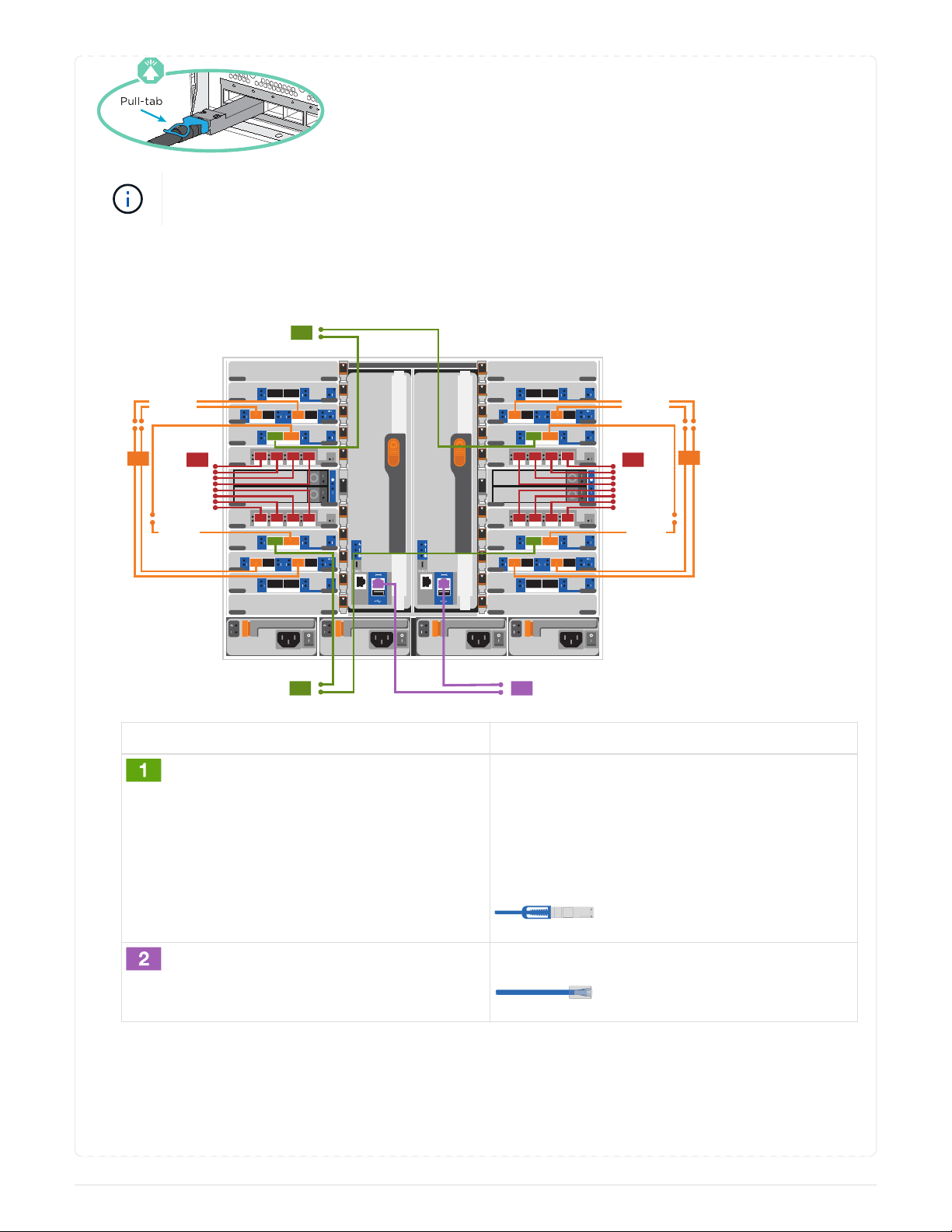
NetApp ASA A900 User manual

ASA A900 systems
Install and maintain
NetApp
July 28, 2023
This PDF was generated from https://docs.netapp.com/us-en/ontap-systems/asa900/install_setup.html on
July 28, 2023. Always check docs.netapp.com for the latest.

Table of Contents
ASA A900 systems . . . . . . . . . . . . . . . . . . . . . . . . . . . . . . . . . . . . . . . . . . . . . . . . . . . . . . . . . . . . . . . . . . . . . . . . Ê1
Install and setup . . . . . . . . . . . . . . . . . . . . . . . . . . . . . . . . . . . . . . . . . . . . . . . . . . . . . . . . . . . . . . . . . . . . . . . . Ê1
Maintain . . . . . . . . . . . . . . . . . . . . . . . . . . . . . . . . . . . . . . . . . . . . . . . . . . . . . . . . . . . . . . . . . . . . . . . . . . . . . Ê19

ASA A900 systems
Install and setup
Start here: Choose your installation and setup experience
You can choose from different content formats to guide you through installing and setting
up your new storage system.
•Quick steps
A printable PDF of step-by-step instructions with live links to additional content.
•Video steps
Video step-by-step instructions.
•Detailed steps
Online step-by-step instructions with live links to additional content.
Quick steps - ASA A900
This page provides graphic instructions for a typical installation of your system from
racking and cabling, through initial system bring-up. Use this content if you are familiar
with installing NetApp systems.
Access the Installation and Setup Instructions PDF poster:
AFF A900 Installation and Setup Instructions
The ASA A900 uses the same installation procedure as the AFF A900 system.
Video steps - ASA A900
There are two videos; one showing how to rack and cable your system and one showing
an example of using the System Manager Guided Setup to perform initial system
configuration.
Video one of two: Hardware installation and cabling
The following video shows how to install and cable your new system.
Animation - AFF A900 Installation and setup instructions
The ASA A900 uses the same installation procedure as the AFF A900 system.
1

Video two of two: Performing end-to-end software configuration
The following video shows end-to-end software configuration for systems running ONTAP 9.2 and later.
[] | https://img.youtube.com/vi/WAE0afWhj1c?/maxresdefault.jpg
Detailed steps - ASA 900
This page provides detailed step-by-step instructions for installing a typical NetApp
system. Use this article if you want more detailed installation instructions.
Step 1: Prepare for installation
To install your system, you need to create an account on the NetApp Support Site, register your system, and
get license keys. You also need to inventory the appropriate number and type of cables for your system and
collect specific network information.
You need to have access to the NetApp Hardware Universe for information about site requirements as well as
additional information on your configured system.
What you need
You might also want to have access to the ONTAP 9 Release Notes for your version of ONTAP for more
information about this system.
You need to provide the following at your site:
•Rack space for the storage system
•Phillips #2 screwdriver
•Additional networking cables to connect your system to your network switch and laptop or console with a
Web browser
Steps
1. Unpack the contents of all boxes.
2. Record the system serial number from the controllers.
3. Inventory and make a note of the number and types of cables you received.
The following table identifies the types of cables you might receive. If you receive a cable not listed in the
table, see the Hardware Universe to locate the cable and identify its use.
NetApp Hardware Universe
2

Type of
cable…
Part number and length Connector type For…
25 GbE data
Cable
X66240A-05 (112-00639),
0.5m
X66240A-2 (112-00598), 2m
X66240A-5 (112-00600), 5m
Network cable
32 Gb FC
(SFP+ Op)
X66250-2 (112-00342), 2m
X66250-5 (112-00344), 5m
X66250-15 (112-00346),
15m
FC optical network cable
40 GbE
network cable
X66100-1 (112-00542), 1m
X66100-3 (112-00543), 3m
X66100-5 (112-00544), 5m
Ethernet data, cluster
network
100 GbE
cable
X66211B-1 (112-00573), 1m
X66211B-2 (112-00574), 2m
X66211B-5 (112-00576), 5m
Network,
NVME storage,
Ethernet data,
cluster network
Optical
cables
X66031A (112-00436), 1m
X66032A (112-00437), 2m
X66033A (112-00438), 3m
FC optical network
Cat 6, RJ-45
(order
dependent)
Part numbers X6585-R6
(112-00291), 3m
X6562-R6 (112-00196), 5m
Management network and
Ethernet data
Micro-USB
console cable
Not applicable Console connection during
software setup on non-
Windows or Mac
laptop/console
Power cables Not applicable Powering up the system
4. Review the ONTAP Configuration Guide and collect the required information listed in that guide.
3

Step 2: Install the hardware
You need to install your system in a 4-post rack or NetApp system cabinet, as applicable.
1. Install the rail kits, as needed.
2. Install and secure your system using the instructions included with the rail kit.
You need to be aware of the safety concerns associated with the weight of the system.
3. Attach cable management devices (as shown).
4. Place the bezel on the front of the system.
The following diagram shows a representation of what a typical system looks like and where the major
components are located at the rear of the system:
4

Step 3: Cable controllers to your network
You can cable the controllers to your network by using the two-node switchless cluster method or by using the
cluster interconnect network.
5

Option 1: Two-node switchless cluster
Management network, data network, and management ports on the controllers are connected to switches.
The cluster interconnect ports are cabled on both controllers.
Before you begin
You must have contacted your network administrator for information about connecting the system to the
switches.
Be sure to check the direction of the cable pull-tabs when inserting the cables in the ports. Cable pull-tabs
are up for all networking module ports.
As you insert the connector, you should feel it click into place; if you do not feel it click,
remove it, turn it around and try again.
1. Use the animation or illustration to complete the cabling between the controllers and to the switches:
Animation - Cable a two-node switchless cluster
Step Perform on each controller
Cable cluster interconnect ports:
•Slot A4 and B4 (e4a)
•Slot A8 and B8 (e8a)
6

Step Perform on each controller
Cable controller management (wrench) ports.
Cable 25 GbE network switches:
Ports in slot A3 and B3 (e3a and e3c) and slot A9
and B9 (e9a and e9c) to the 25 GbE network
switches.
40GbE host network switches:
Cable host‐side b ports in slot A4 and B4 (e4b)
and slot A8 and B8 (e8b) to the host switch.
Cable 32 Gb FC connections:
Cable ports in slot A5 and B5 (5a, 5b, 5c, and 5d)
and slot A7 and B7 (7a, 7b, 7c, and 7d) to the 32
Gb FC network switches.
•Strap the cables to the cable management
arms (not shown).
•Connect the power cables to the PSUs and
connect them to different power sources (not
shown). PSU 1 and 3 provide power to all
side A components, while PSU2 and PSU4
provide power to all side B components.
Option 2: Switched cluster
Management network, data network, and management ports on the controllers are connected to switches.
The cluster interconnect and HA ports are cabled on to the cluster/HA switch.
Before you begin
You must have contacted your network administrator for information about connecting the system to the
switches.
Be sure to check the direction of the cable pull-tabs when inserting the cables in the ports. Cable pull-tabs
are up for all networking module ports.
7

As you insert the connector, you should feel it click into place; if you do not feel it click,
remove it, turn it over and try again.
1. Use the animation or illustration to complete the cabling between the controllers and to the switches:
Animation - Cable a switched cluster
B5
B6
B4
B3
B2
B1
B10
B9
B8
B7
B11
A5
A6
A4
A3
A2
A1
A10
A9
A8
A7
A11
6- 2
6- 1
a b c d
a b
a b
a b
6- 2
6- 1
Controller A
PSU 1
Controller B
PSU 2 PSU 3 PSU 4
abcd
a b c d
a b c d a b c d
a b
a b
a b
a b a b
abcd
abcdabcd
1
To cluster switches
1
To cluster switches
34 4 3
To 25 GbE
network
switches
To host
network
switch
To 32 Gb
FC network
switches
To 32 Gb
FC network
switches
To 25 GbE
network
switches
To host
network
switch
2To management
network switches
Step Perform on each controller
Cable cluster interconnect a ports:
•Slot A4 and B4 (e4a) to the cluster network
switch.
•Slot A8 and B8 (e8a) to the cluster network
switch.
Cable controller management (wrench) ports.
8

Step Perform on each controller
Cable 25GbE network switches:
Ports in slot A3 and B3 (e3a and e3c) and slot A9
and B9 (e9a and e9c) to the 25 GbE network
switches.
40GbE host network switches:
Cable host‐side b ports in slot A4 and B4 (e4b)
and slot A8 and B8 (e8b) to the host switch.
Cable 32 Gb FC connections:
Cable ports in slot A5 and B5 (5a, 5b, 5c, and 5d)
and slot A7 and B7 (7a, 7b, 7c, and 7d) to the 32
Gb FC network switches.
•Strap the cables to the cable management
arms (not shown).
•Connect the power cables to the PSUs and
connect them to different power sources (not
shown). PSU 1 and 3 provide power to all
side A components, while PSU2 and PSU4
provide power to all side B components.
Step 4: Cable controllers to drive shelves
Cable either a single NS224 drive shelf or two NS224 drive shelves to your controllers.
9

Option 1: Cable the controllers to a single NS224 drive shelf
You must cable each controller to the NSM modules on the NS224 drive shelf.
Before you begin
•Be sure to check the illustration arrow for the proper cable connector pull-tab orientation. The cable
pull-tab for the storage modules are up, while the pull tabs on the shelves are down.
As you insert the connector, you should feel it click into place; if you do not feel it click,
remove it, turn it around and try again.
1. Use the following animation or drawings to cable your controllers to a single NS224 drive shelf.
Animation - Cable a single NS224 shelf
B5
B6
B4
B3
B2
B1
B10
B9
B8
B7
B11
A5
A6
A4
A3
A2
A1
A10
A9
A8
A7
A11
6- 2
6- 1
a b c d
a b
a b
a b
6- 2
6- 1
abcd
a b c d
a b c d a b c d
a b
a b
a b
a b a b
abcd
abcdabcd
Shelf 1
NSM A
NSM B
e0a
e0a
e0b
e0b
Controller A Controller B
10

Step Perform on each controller
•Connect controller A port e2a to port e0a on
NSM A on the shelf.
•Connect controller A port e10b to port e0b on
NSM B on the shelf.
100 GbE cable
•Connect controller B port e2a to port e0a on
NSM B on the shelf.
•Connect controller B port e10b to port e0b on
NSM A on the shelf.
100 GbE cable
Option 2: Cable the controllers to two NS224 drive shelves
You must cable each controller to the NSM modules on the NS224 drive shelves.
Before you begin
•Be sure to check the illustration arrow for the proper cable connector pull-tab orientation. The cable
pull-tab for the storage modules are up, while the pull tabs on the shelves are down.
As you insert the connector, you should feel it click into place; if you do not feel it click,
remove it, turn it around and try again.
1. Use the following animation or diagram to cable your controllers to two NS224 drive shelves.
Animation - Cable two NS224 shelves
11

12

Step Perform on each controller
•Connect controller A port e2a to NSM A e0a
on shelf 1.
•Connect controller A port e10b to NSM B e0b
on shelf 1.
•Connect controller A port e2b to NSM B e0b
on shelf 2.
•Connect controller A port e10a to NSM A e0a
on shelf 2.
100 GbE cable
•Connect controller B port e2a to NSM B e0a
on shelf 1.
•Connect controller B port e10b to NSM A e0b
on shelf 1.
•Connect controller B port e2b to NSM A e0b
on shelf 2.
•Connect controller B port e10a to NSM B e0a
on shelf 2.
100 GbE cable
Step 5: Complete system setup and configuration
You can complete the system setup and configuration using cluster discovery with only a connection to the
switch and laptop, or by connecting directly to a controller in the system and then connecting to the
management switch.
13

Option 1: If network discovery is enabled
If you have network discovery enabled on your laptop, you can complete system setup and configuration
using automatic cluster discovery.
1. Use the following animation or drawing to set one or more drive shelf IDs:
The NS224 shelves are pre-set to shelf ID 00 and 01. If you want to change the shelf IDs, you must
create a tool to insert into the hole where button is located. see Change a shelf ID - NS224 shelves
for detailed instructions.
Animation - Set NVMe drive shelf IDs
Shelf end cap
Shelf faceplate
Shelf ID LED
Shelf ID setting button
2. Turn on the power switches on the power supplies to both nodes.
Animation - Turn on the power to the controllers
14

Initial booting may take up to eight minutes.
3. Make sure that your laptop has network discovery enabled.
See your laptop’s online help for more information.
4. Use the following animation to connect your laptop to the Management switch.
Animation - Connect your laptop to the Management switch
5. Select an ONTAP icon listed to discover:
a. Open File Explorer.
b. Click network in the left pane.
c. Right click and select refresh.
d. Double-click either ONTAP icon and accept any certificates displayed on your screen.
XXXXX is the system serial number for the target node.
15

System Manager opens.
6. Use System Manager guided setup to configure your system using the data you collected in the
ONTAP Configuration Guide.
7. Set up your account and download Active IQ Config Advisor:
a. Log in to your existing account or create an account.
NetApp Support Registration
b. Register your system.
NetApp Product Registration
c. Download Active IQ Config Advisor.
NetApp Downloads: Config Advisor
8. Verify the health of your system by running Config Advisor.
9. After you have completed the initial configuration, go to the ONTAP & ONTAP System Manager
Documentation Resources page for information about configuring additional features in ONTAP.
Option 2: If network discovery is not enabled
If you are not using a Windows or Mac-based laptop or console or if auto discovery is not enabled, you
must complete the configuration and setup using this task.
1. Cable and configure your laptop or console:
a. Set the console port on the laptop or console to 115,200 baud with N-8-1.
See your laptop or console’s online help for how to configure the console port.
b. Connect the console cable to the laptop or console using the console cable that came with your
system, and then connect the laptop to the management switch on the management subnet.
B5
B6
B4
B3
B2
B1
B10
B9
B8
B7
B11
A5
A6
A4
A3
A2
A1
A10
A9
A8
A7
A11
6- 2
6- 1
a b c d
a b
a b
a b
6- 2
6- 1
abcd
a b c d
a b c d a b c d
a b
a b
a b
a b a b
abcd
abcdabcd
Management subnet
2
A10
A9
Client
1
c. Assign a TCP/IP address to the laptop or console, using one that is on the management subnet.
2. Use the following animation to set one or more drive shelf IDs:
The NS224 shelves are pre-set to shelf ID 00 and 01. If you want to change the shelf IDs, you must
create a tool to insert into the hole where button is located. see Change a shelf ID - NS224 shelves
16

Initial booting may take up to eight minutes.
4. Assign an initial node management IP address to one of the nodes.
If the
management
network has
DHCP…
Then…
Configured Record the IP address assigned to the new controllers.
Not configured a. Open a console session using PuTTY, a terminal server, or the equivalent
for your environment.
Check your laptop or console’s online help if you do not know
how to configure PuTTY.
b. Enter the management IP address when prompted by the script.
5. Using System Manager on your laptop or console, configure your cluster:
a. Point your browser to the node management IP address.
The format for the address is https://x.x.x.x.
b. Configure the system using the data you collected in the ONTAP Configuration Guide
6. Set up your account and download Active IQ Config Advisor:
a. Log in to your existing account or create an account.
NetApp Support Registration
b. Register your system.
NetApp Product Registration
c. Download Active IQ Config Advisor.
NetApp Downloads: Config Advisor
7. Verify the health of your system by running Config Advisor.
8. After you have completed the initial configuration, go to the ONTAP & ONTAP System Manager
18
Table of contents
Other NetApp Disk Array System manuals

NetApp
NetApp AFF A900 User manual

NetApp
NetApp E Series User manual

NetApp
NetApp AFF A300 User manual

NetApp
NetApp AFF A900 User manual

NetApp
NetApp FAS User manual

NetApp
NetApp AFF A700 Manual

NetApp
NetApp E2760 User manual

NetApp
NetApp FAS2700 Series User manual

NetApp
NetApp AFF A220 User manual

NetApp
NetApp EF Series Manual
Popular Disk Array System manuals by other brands

HP
HP D6030A - NetServer - E50 features and benefits

HP
HP StorageWorks XP1024 System configuration

HP
HP StorageWorks XP10000 - Disk Array user guide

TRADEDX
TRADEDX SSR-4N108L user manual

VERITAS
VERITAS NetBackup 5240 manual

ATTO Technology
ATTO Technology Diamond Storage Array S-Class Installation and operating manual