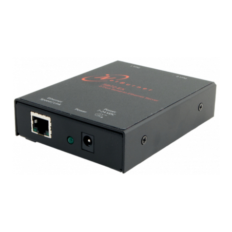
NetBurner SBL2e User manual

SBL2e Dual Serial-to-Ethernet User's Manual Page 2
Table of Contents
1. Overview.......................................................................................................................................4
2. IPSetup Software Utility..............................................................................................................4
3. Initial Configuration...................................................................................................................4
3.1 Serial Port Hardware......................................................................................................................5
3.2 Network Configuration...................................................................................................................5
3.3 Operational Configuration.............................................................................................................6
4. Web Page Configuration.............................................................................................................7
4.1 Network IP Settings Configuration...............................................................................................7
4.2 Incoming Connections (Server Mode)...........................................................................................8
4.3 Outgoing Connections (Client Mode)............................................................................................9
4.4 Custom Packetization ...................................................................................................................10
5. Serial Settings............................................................................................................................12
6. Password Settings......................................................................................................................13
7. Multi-Function Pin Control......................................................................................................14
7.1 Multi-Function Pin Control .........................................................................................................15
7.2 Command Syntax..........................................................................................................................15
7.3 Machine Command Mode............................................................................................................17
7.4 Machine Command Examples .....................................................................................................18
7.4.1 Set Pins 14 and 15 to GPIO Outputs..........................................................................................................18
7.4.2 Set All GPIO Pins as Inputs and Readback ...............................................................................................18
7.4.3 Read A/D Inputs ........................................................................................................................................18
8. AT Commands...........................................................................................................................19
8.1 Enter and Exit Command Mode..................................................................................................19
8.2 Command Syntax..........................................................................................................................20
8.3 System/Network Configuration ...................................................................................................21
8.4 Serial Port Configuration.............................................................................................................22
8.4.1 Custom Packetization ................................................................................................................................23
8.5 GPIO Server and Analog to Digital Readback...........................................................................24
8.6 AT Command Examples...............................................................................................................25
8.6.1 Changing the System IP Address...............................................................................................................25
8.6.2 Configuring the Serial Server Listen Port..................................................................................................25
8.6.3 Configure Outgoing Network Client Connection......................................................................................25
8.6.4 Read Analog to Digital Input Channel 1....................................................................................................26
8.6.5 Change Pin to GPIO and Set Output to High ............................................................................................26
9. LEDs ..........................................................................................................................................27
10. RS-232 NULL Modem Wiring..............................................................................................27
11. Network IP Address Configuration......................................................................................27
Downloaded from Elcodis.com electronic components distributor

SBL2e Dual Serial-to-Ethernet User's Manual Page 3
12. Web Browsers and Proxy Servers.........................................................................................28
13. Testing with a Telnet Connection.........................................................................................28
14. Telnet to Serial Test Procedure.............................................................................................29
Revision History ................................................................................................................................30
Downloaded from Elcodis.com electronic components distributor

SBL2e Dual Serial-to-Ethernet User's Manual Page 4
1. Overview
The NetBurner SBL2e is a dual serial-to-Ethernet device that will enable your serial device to
communicate on an Ethernet network using TCP or UDP. In addition to the serial capabilities, the
SBL2e also provides a separate network connection command channel for control of digital I/O
signals and analog-to-digital readback. A list of features and functions is below:
2 Serial UARTs, TTL level, baud rates from 300 to 115,200
4 12-bit analog to digital converters, 0-3.3VDC input
Up to 10 Digital inputs/outputs, also referred to as GPIO
10/100 Ethernet
Serial to Ethernet capability through TCP or UDP
DHCP and Static IP addressing
Custom data packetization options
Web page configuration
AT command set configuration and operation
3.3VDC input power @ 250mA max
2. IPSetup Software Utility
Setup and configuration of your SBL2e requires the IPSetup.exe Windows PC utility available for
download at www.netburner.com, in the Support > Public Downloads section:
http://www.netburner.com/support/public_downloads.html
3. Initial Configuration
Before you can begin using your SBL2e, three areas of configuration are required to tell your
SBL2e what type of serial interface you want to use, the network IP address network port number,
and the serial data baud rate.
1. Hardware configuration
2. Network configuration
3. Operational configuration
Downloaded from Elcodis.com electronic components distributor

SBL2e Dual Serial-to-Ethernet User's Manual Page 5
3.1 Serial Port Hardware
The SBL2e has two asynchronous UART type serial ports, referred to as Port 0 and Port 1. The
SBL2e provides to TTL level UART serial ports:
Port 0 signals : TX, RX, RTS, CTS
Port 1 signals : TX, RX
If you need RS-232 electrical levels, then you must add the appropriate level shifters to the TTL
signals.
The “Debug Serial Port”, or Debug Port for short, is used to display status messages from the
application. If your application needs only a single serial port we recommend setting the other serial
port to “Debug”.
3.2 Network Configuration
1. Run IPSetup.exe (by double clicking its icon). This program is located on the SBL2e product
page at www.netburner.com. To view the Advance Settings, click on the Advanced button (the
button name will change to Basic). In this example, I am using Uart 1 as my Monitor port
(screen shot below).
2. Locate your SBL2e in the "Select a Unit" pane by matching its MAC address. The MAC
address is located on the bottom of your SBL2e. If your SBL2e device does not appear in the list
box, verify the power, speed, and link LEDs are illuminated, and click the Search Again button.
If you are still unable to see your SBL2e, remove power, correct any cabling errors, reapply
power, and click the Search Again button. Note: IP Setup uses a UDP broadcast protocol and
will not operate through a router.
FIREWALLS: IPSetup uses UDP and TCP port number 20034. If your computer’s
firewall is blocking this port number you will need to either disable the firewall, or add a
rule to the firewall to allow communication on this port number.
3. If your network supports DHCP (factory default): The assigned IP Address will appear in the
"Select a Unit" pane. Write down this address. If your network does not support DHCP,
configure the IP Address and Network Mask fields as shown in the screen shot below. If you
need help selecting values, please read the "Selecting an IP Address" section at the end of this
guide. After you have entered all of your values, click the Set button in the center of the IP
Setup window to configure your SBL2e with its new parameters. Note: If you do not click the
Set button, your values will not be saved. If you have multiple NetBurner devices, make sure
you selected your SBL2e in the "Select a Unit" pane (as shown in the screen shot) before you
input your information.
Downloaded from Elcodis.com electronic components distributor

SBL2e Dual Serial-to-Ethernet User's Manual Page 6
A screen-shot of IPSetup is shown below:
3.3 Operational Configuration
Once the network parameters are, you can use the web server interface or serial AT commands to
modify the settings of your SBL2e. We recommend using the web interface first to familiarize
yourself with the operation of the SBL2e. To access the web page, click on the Launch Webpage
button in IP Setup, or you can open your web browser, and enter the numeric IP Address in the
address field (e.g. http://10.1.1.110).
Downloaded from Elcodis.com electronic components distributor

SBL2e Dual Serial-to-Ethernet User's Manual Page 7
4. Web Page Configuration
Once you have configured the IP address of your device you can connect to the SBL2e web server
to configure your serial and network settings. The SBL2e can be configured in one of 3 modes:
1. TCP Server: Listen for incoming TCP connections.
2. TCP Client: Connect to a target network address when serial data is available, or you can
also establish a network connection on SBL2e power-up.
3. UDP: Send and receive using UDP packets
4.1 Network IP Settings Configuration
The first section of the Network Configuration page is used to select DHCP or static IP addressing.
If you select DHCP, and the you have a DHCP server on your network, the DHCP assigned values
will be displayed. To select a static IP address chance the Address Mode to Static, and enter your
values in the Static Settings fields.
Device Name
Specifies the device name to send to your DHCP server.
Address Mode
Select between DHCP and Static IP address settings.
Device IP Address
Device Subnet Mask
Device Gateway
Device DNS
If Address Mode is set to DHCP, your DHCP server will provide these
values and they will be displayed in the DHCP Assigned Values column.
If you wish to specify these values yourself set the Address Mode to
“static” and type the values in the appropriate fields. Note that if you do
not specify a Gateway or DNS server you will not be able to communicate
outside your LAN.
Ethernet Link
Normal = Auto-negotiate. You may also force 10MB or 100MB modes.
Downloaded from Elcodis.com electronic components distributor

SBL2e Dual Serial-to-Ethernet User's Manual Page 8
4.2 Incoming Connections (Server Mode)
This section configures the SBL2e in a device server mode in which it listens for incoming TCP
connections (or UDP packets if enabled) for each serial port.
Listen for incoming network
connections
Select checkbox to enable the port to listen for
incoming TCP connection requests or UDP packets.
Checking this box will override the TCP Client mode.
Listening network port
Port number to listen on. The default port is 23 (telnet).
The listen port numbers for Port0 and Port1 must be
different.
Timeout and disconnect after this many
seconds of inactivity.
Terminate TCP connection if no incoming network
data or outgoing serial data has occurred. This is useful
because there is no way to detect if a client has crashed
or abnormally terminated unless unacknowledged data
exists and times out. A value of 0 disables this feature.
This field has no effect in UDP mode.
Allow new connection if the existing
connection has been idle for this many
seconds.
Similar to the disconnect timeout, but does not
disconnect a connection until a new connection is
requested. A value of 0 disables this feature. This field
has no effect in UDP mode.
Downloaded from Elcodis.com electronic components distributor

SBL2e Dual Serial-to-Ethernet User's Manual Page 9
4.3 Outgoing Connections (Client Mode)
Make outgoing connections
Selects between connect on power-up for a permanent
TCP connection, or make a TCP connection when
serial data available. This feature has no effect on
UDP.
Connect on network port
Specifies destination TCP or UDP port number
Connect to this address
Specifies destination IP address for TCP or UDP.
When using UDP you must specify an address and port
number in this section, or enable the Learn UDP Reply
Address feature in the Custom Packetization section.
Timeout and disconnect after this many
seconds of inactivity.
Terminate TCP connection if no incoming network
data or outgoing serial data has occurred. This is useful
because there is no way to detect if a client has crashed
or abnormally terminated unless unacknowledged data
exists and times out. A value of 0 disables this feature.
This feature has no effect on UDP.
Retry failed outgoing connections after
this many seconds.
Number of seconds to wait before retrying an outgoing
connection. This feature has no effect on UDP.
Downloaded from Elcodis.com electronic components distributor

SBL2e Dual Serial-to-Ethernet User's Manual Page 10
4.4 Custom Packetization
Custom packetization can apply to TCP and UDP communication. Unlike TCP, UDP is a
connectionless protocol. The SBL2e provides two methods to determine the destination network IP
address: you can specify a static IP address, or you can use the source IP address of the last received
UDP packet by selecting the “Learn UDP Reply Address” checkbox.
Use custom packetization logic
Enables/disables custom packetization settings
Use UDP instead of TCP
Check to enable UDP
Learn UDP reply Address
Send outbound serial to the IP address from the last
received UDP packet. Useful for clients that may have
changing IP addresses. If not using this feature, you
must specify the destination IP address and port
number in the Outgoing Connections section.
Number of characters to accumulate
before sending TCP/UDP packet
Maximum number of characters to accumulate from
the serial port before sending them out the network
port. This setting will be overridden if the
accumulation delay time setting is used and the delay
time expires.
Number msec to wait for accumulated
characters (0 waits forever)
Maximum wait time in milliseconds for received serial
characters before sending any available characters out
the network port.
Flush TCP frame when this character is
received (Enter NA to disable)
Send all accumulated serial data upon receipt of this
character from the serial port. Enter the decimal value
of the character. For example, a line feed is 10.
Downloaded from Elcodis.com electronic components distributor

SBL2e Dual Serial-to-Ethernet User's Manual Page 12
5. Serial Settings
The SBL2e provides two TTL level UARTs, Port 0 and Port 1. The RS-232 setting will enable the
TTL level signals for transmit, receive, RTS and CTS, but you will need to add external level
shifters if you need the RS-232 electrical signals instead of 0-3.3VDC TTL
RS-232 Select for use as TTL or if you have a RS-232 level shifter.
DEBUG Specifies whether or not to use the serial port as stdin, stdout and stderr
for serial status messages or debugging.
Data Port Settings (If both are DEBUG,
defaults to Port 0)
Select serial mode RS-232 or DEBUG.
Data Baud Rate
Set serial baud rate
Data bits
Serial data bits
Data parity
Serial parity
Stop bits
Number of stop bits
Flow control
Set to None for no flow control. If using RS-232 or
TTL valid selections are None, Xon/Xoff software flow
control, or RTS/CTS hardware flow control.
Downloaded from Elcodis.com electronic components distributor

SBL2e Dual Serial-to-Ethernet User's Manual Page 13
6. Password Settings
Use the Password Settings screen to enable, disable or change an existing password. Only one
password is allowed. To clear a password leave the fields blank and click on submit.
Downloaded from Elcodis.com electronic components distributor

SBL2e Dual Serial-to-Ethernet User's Manual Page 14
7. Multi-Function Pin Control
The 16-pin interface connector of the SBL2e has 10 signals with multiple functions, such as general
purpose digital I/O, analog to digital conversion, and serial hardware handshaking. The GPIO
Settings configuration screen enables you to select the functions of the multi-function pins.
Downloaded from Elcodis.com electronic components distributor

SBL2e Dual Serial-to-Ethernet User's Manual Page 15
7.1 Multi-Function Pin Control
In addition to Serial-to-Ethernet capabilities, the SBL2e provides external control and readback
functionality for General Purpose Input/Outputs and Analog to Digital inputs.
The function of each multi-function pin is set in the GPIO configuration web page (GPIO is
the most common function).
The "GPIO Network Server" on the SBL2e listens on the TCP port number specified in the
"GPIO Server Port" field. For a quick test, you can use the telnet utility: "telnet <ip address>
1000" for the default port of 1000.
Some pins are fixed, but are shown for reference.
The pin configuration can only be done through the HTML web page or serial AT
commands.
Access to the pin functions can only be done through a TCP connection to the GPIO
Network Server (not the serial port).
7.2 Command Syntax
Once you have established a TCP connection to the GPIO Network Server, the following
commands can be used, where "xx" is a value from 03 to 15. All commands and queries must be
terminated by a line feed character: 0x0A. You may also terminate with a carriage return and line
feed; the carrage return will be ignored by the parser.
General Purpose I/O Functions:
Pxx = 0
Set pin output low.
Pxx = 1
Set pin out put high.
Pxx = I
Set pin as input.
Pxx?
Read input value. Note that this command will automatically program the pin as an
input. The value of an output pin cannot be read. The return value is 0 or 1 in the
format: "0, OK\r\n" or "1, OK\r\n".
Examples:
"P14=0\n" returns "0, OK\r\n"
"P15?\n" returns "1, OK\r\n" if the pin is logic high
Analog to Digital Functions:
Pxx?
Read input value. The value read is a number from 0-4095 representing the number
of counts. The counts represent a ratiometric value to the 3.3V reference voltage.
The maximum voltage input is 3.3V.
Example:
"P07?\n" , returns "1234, OK\r\n" if the number of counts was 1,234.
Downloaded from Elcodis.com electronic components distributor

SBL2e Dual Serial-to-Ethernet User's Manual Page 16
Network Functions:
X
If the TCP client application, such as telnet, sends an 'X', the connection with the
GPIO Network Server will be terminated.
Example:
"X\n" , returns "0, Closing\r\n"
Character Echo:
Echos characters back to TCP client. Default is echo off.
E
Enable echo
e
Disable echo
Example:
"E\n" , returns "0, Echo on\r\n"
Firmware Version :
V
Query firmware version
Example:
"V\n" , returns "0, Firmware Version: SBL2e 1.3 8/5/2009\r\n"
Command and Query Return Strings:
Each command and query will return an integer value followed by a ',' and optional text to provide
details on the response.
Any successful command will return: "0, OK\r\n".
Any command error will return a negative number, followed by an explanation of the error.
For example, sending the command "abcd\n" returns: "-3, Syntax Error\r\n".
Any readback/query response will be the value of the readback followed by the status. For
example, sending "P07?\n" could return "2034, OK\n". The 2034 is the decimal number of
counts.
Any readback/query that generates an error will return a negative number instead of the
readback value.
Error Codes:
-1
Pin not in GPIO mode
-2
Invalid pin number
-3
Command syntax error
Note: At this time the I2C functions are not supported.
Downloaded from Elcodis.com electronic components distributor

SBL2e Dual Serial-to-Ethernet User's Manual Page 17
7.3 Machine Command Mode
The “Machine Command Mode” is so named because the data sent and received is in hex or binary,
as opposed to the AT Command Mode which is more of a human readable text syntax and format.
All non-programmable pins such as power, ground and /RSTI, will read back as 0 and programming
commands will have no effect on them.
Syntax:
All commands are terminated with a linefeed, which is a hexadecimal value of 0x10, also
represented by a „\n‟ character in C. A carriage return value of 0x13 (or „\r‟) is ignored, so
commands may be terminated with „\n‟ or “\r\n”.
Command parameters are in hexadecimal format, with the most significant bit (MSB) first.
Return Values
Commands to set parameters will return a status value 0 on success, or 1 for a syntax error.
Commands that return values will be in format: “<status>,<result>”, where status is 0 (success)
or 1 (syntax error) and the return value is one or more hexadecimal values, depending on the
command. Hexadecimal values have the MSB first.
Return values are terminated by “\r\n”.
Command Summary:
MGxxxx GPIO Enable: Set pin configuration, primary function (0) or GPIO mode (1).
MG GPIO Enable Query: Return primary/GPIO pin configuration.
MRxxxx GPIO Direction: Set the GPIO pin direction, input (0) or output (1).
MR GPIO Direction Query: Return GPIO pin direction.
MOxxxx GPIO Output Set: Set individual GPIO output pins, low (0) or high (1).
MO GPIO Output Query: Return programmed state of all GPIO output pins.
MH Set all GPIO output pins high (1)
ML Set all GPIO output pins low (0)
MP Save current settings as the power-on state
MQ Query all A/D and GPIO values
MT Terminate the GPIO command TCP connection
M? Return all GPIO input and output pin values, low (0) or high (1).
Downloaded from Elcodis.com electronic components distributor

SBL2e Dual Serial-to-Ethernet User's Manual Page 18
7.4 Machine Command Examples
7.4.1 Set Pins 14 and 15 to GPIO Outputs
MG6000 // Set pin configuration to GPIO mode for both pins
0 // Return value of 0 for success
MR6000 // Set GPIO pin direction to output for both pins.
0 // Return value of 0 for success
MO6000 // Set GPIO output pin value to 1 for both pins
0 // Return value of 0 for success
MO // Query all output pin values
0,0x6000 // Success, driving outputs high on pins 14, 15
MO4000 // Set pin 15 low, pin 14 high
0 // Success
MO // Query all output pin values
0,0x4000 // Pin 15 low, pin 14 high
M? // Query all input and output pins
0,0x5BCC // Pin 15 low, pin 14 high, remaining pins report input value.
7.4.2 Set All GPIO Pins as Inputs and Readback
MG7BCC // Set pin configuration to GPIO mode for all GPIO capable pins
0 // Return value of 0 for success
MR0000 // Set GPIO pin direction to input for all pins.
0 // Return value of 0 for success
M? // Read all GPIO input pin values
0,0x3BCC // Return value of 0 for success (note pins are floating inputs on dev. board)
7.4.3 Read A/D Inputs
MG03C0 // Set pin configuration to A/D primary function for all 4 A/D inputs
0 // Return value of 0 for success
MQ // Read A/D inputs
// 0=success, A/D values of pins 7,8,9,10, all GPIO inputs as a 16-bit word
0, 0x4F38, 0x4910, 0x42A0, 0x4FE0, 0x3BCC
Downloaded from Elcodis.com electronic components distributor

SBL2e Dual Serial-to-Ethernet User's Manual Page 19
8. AT Commands
As an alternative to the web page configuration, you can configure the SBL2e over a serial port
using an AT command format. The configuration sequence is:
1. Enter command mode
2. Send configuration change commands
3. Save changes and exit
The AT command operation is different for configuration commands versus GPIO pin
programming commands. Please refer to “GPIO Server and Analog to Digital Readback” later in
this section for additional details.
8.1 Enter and Exit Command Mode
AT configuration commands can only be processed when the SBL2e is in “AT Command Mode”.
To enter AT command mode:
1. Pause for 1 second (send no data).
2. Send “+++”.
3. Wait for 1 second.
4. The device will respond with “\r\nOK”.
To exit command mode:
1. Wait 30 seconds for timeout, any changes will be lost.
2. Send “AT&X” or “ATO” to exit and discard any changes.
3. Send “AT&P” to exit and save new settings.
4. Send “AT&F” to reset all settings to factory default (does not save).
Returns:
1, Returning to active connection
2, Returning to listening connection
3, Returning to active UDP mode
0, Returning to idle
Exiting command mode with any changes terminate all existing TCP connections.
Downloaded from Elcodis.com electronic components distributor

SBL2e Dual Serial-to-Ethernet User's Manual Page 20
8.2 Command Syntax
The format of an AT command is:
AT#<command>=<parameter>,<parameter>, ….. <cr>
The format of an AT query is:
AT#<command>?<cr>
Syntax rules:
All white space outside quotations is ignored
All commands and queries are terminated by a carriage return <cr> (decimal value 13), if a
line feed <lf> follows a <cr>, it will be ignored.
Downloaded from Elcodis.com electronic components distributor
Other manuals for SBL2e
1
Table of contents
Other NetBurner Network Hardware manuals
Popular Network Hardware manuals by other brands

Avigilon
Avigilon NVR5-10GBASET-A1 installation guide

ADTRAN
ADTRAN Quad T1 IMA Installation and maintenance practice

NEXTIVITY
NEXTIVITY SHIELD MegaFi quick start guide

Nokia
Nokia ONT G-010G-R Quick reference guide
ADLINK Technology
ADLINK Technology MCM-204 user manual

Moxa Technologies
Moxa Technologies TRC-2190 Series Quick installation guide
Comelit
Comelit IPNVR064A08NBSL manual
Mobatime
Mobatime DTS 4020.timebridge Mounting and instruction manual

AFJ Instruments
AFJ Instruments LT32C/10 operating manual

Panasonic
Panasonic LJ-SK56A user manual
TP-Link
TP-Link TL-PA4020P Quick installation guide

D-Link
D-Link xStack Storage DSN-4000 Series Cli user's guide


