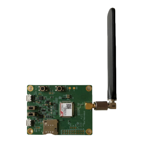
SimCom SIM28 Series User manual

SIMCom GNSS Modules
EVB Kit User guide_V1.00
(Apply to SIM28 series、SIM68 series、SIM33ELA、SIM39EA series )

SIMCom GNSS Modules EVB kit User Guide
SIMCom GNSS Modules EVB Kit User Guide _V1.00 2014-05-20
2
Document Title: GNSS Modules EVB Kit User Guide
Version: 1.00
Date: 2014-5-20
Status: Release
Document Control ID: GNSS Modules EVB Kit User Guide _V1.00
General Notes
SIMCom offers this information as a service to its customers, to support application and
engineering efforts that use the products designed by SIMCom. The information provided is based
upon requirements specifically provided to SIMCom by the customers. SIMCom has not
undertaken any independent search for additional relevant information, including any information
that may be in the customer’s possession. Furthermore, system validation of this product designed
by SIMCom within a larger electronic system remains the responsibility of the customer or the
customer’s system integrator. All specifications supplied herein are subject to change.
Copyright
This document contains proprietary technical information which is the property of SIMCom
Limited., copying of this document and giving it to others and the using or communication of the
contents thereof, are forbidden without express authority. Offenders are liable to the payment of
damages. All rights reserved in the event of grant of a patent or the registration of a utility model
or design. All specification supplied herein are subject to change without notice at any time.
Copyright © Shanghai SIMCom Wireless Solutions Ltd. 2014

SIMCom GNSS Modules EVB kit User Guide
SIMCom GNSS Modules EVB Kit User Guide _V1.00 2014-05-20
3
Contents
Contents ............................................................................................................................................3
Version History .................................................................................................................................5
1. Introduction...................................................................................................................................6
2. SIM68_EVB Overview.................................................................................................................6
2.1 Detailed description of SIM68-EVB....................................................................................6
2.2 USB Interface.......................................................................................................................7
3. Illustration of testing.....................................................................................................................8
3.1 An example of USB driver installation ................................................................................8
3.2 Connecting and run............................................................................................................12
4. SIMCom GPS Testing Tool........................................................................................................12
4.1 Port setting .........................................................................................................................12
4.2 Click to RUN......................................................................................................................13
4.3 TTFF Test...........................................................................................................................15
4.4 PMTK command input.......................................................................................................16
5. Firmware update .........................................................................................................................17
6 Acronyms and abbreviation .........................................................................................................23

SIMCom GNSS Modules EVB kit User Guide
SIMCom GNSS Modules EVB Kit User Guide _V1.00 2014-05-20
4
Figure Index
FIGURE 1: SIM68-EVB COMPONENTS FUNCTION.........................................................................6
FIGURE 2: USB INTERFACE................................................................................................................7
FIGURE 3: USB DRIVER INSTALLATION STEP1..............................................................................8
FIGURE 4: USB DRIVER INSTALLITION STEP2...............................................................................9
FIGURE 5: USB DRIVER INSTALLATION STEP3..............................................................................9
FIGURE 6: USB DRIVER INSTALLATION STEP4............................................................................10
FIGURE 7: USB DRIVER INSTALLITION STEP5.............................................................................10
FIGURE 8: USB DRIVER INSTALLITION STEP6.............................................................................11
FIGURE 9: USB DRIVER INSTALLATION STEP7............................................................................11
FIGURE 10: USB DRIVER INSTALLATION STEP8..........................................................................11
FIGURE 11: USB DRIVER INSTALLATION STEP9..........................................................................12
FIGURE 12: TESTING TOOL INTERFACE ........................................................................................13
FIGURE 13: SETTING WINDOW........................................................................................................13
FIGURE 14: CLICK TO RUN...............................................................................................................14
FIGURE 15: THE MODULE IS RUNNING.........................................................................................14
FIGURE 16: SETTING TTFF TESTING CONFIGURATION.............................................................15
FIGURE 17: TTFF TEST RESULT .......................................................................................................16
FIGURE 18: COMMAND WINDOW...................................................................................................16
FIGURE 19: POWER FLASH MAIN UI..............................................................................................17
FIGURE 20: ENTER CODE..................................................................................................................18
FIGURE 21: THE MAIN UI..................................................................................................................18
FIGURE 22: SETTING PORT...............................................................................................................19
FIGURE 23: SETTING BAUDRATE....................................................................................................19
FIGURE 24: DETAILED SETTINGS ...................................................................................................20
FIGURE 25: DA FILE IN DOWNLOADING PROCEEDING.............................................................21
FIGURE 26: ROM FILE IN DOWNLOADING PROCEEDING .........................................................21
FIGURE 27: FIRMWARE UPDATE SUCCEEDS................................................................................22
Table Index
TABLE 1: USB PIN DEFINITION..........................................................................................................7
TABLE 2: ACRONYMS AND ABBREVIATIONS..............................................................................23

SIMCom GNSS Modules EVB kit User Guide
SIMCom GNSS Modules EVB Kit User Guide _V1.00 2014-05-20
5
Version History
Data Version Description of change Author
2012-12-11 1.00 Origin Honggang. Ma
2014-5-20 1.00 Modify the document for SIMcom GNSS modules Chengbing.wu

SIMCom GNSS Modules EVB kit User Guide
1. Introduction
This document introduces the usage of SIM68 EVB kit, it applies to most of SIMCom GNSS
Modules. User can get useful information about the SIM68 EVB quickly through this document.
This document is subject to change without notice at any time.
2. SIM68_EVB Overview
2.1 Detailed description of SIM68-EVB
The chapter introduces the functions of each component.
Figure 1: SIM68-EVB components function
A: USB interface, support USB communication with SIMcom GNSS module, and also power the
SIM68-EVB.
B: S301, Power switch, push up to power the EVB and module, push down to power off.
C: S202, NMEA output select. Push up to choose USB port. Push down to close.
D: UART to RS232 transceiver
E, F: Select for receiving NMEA data from A or K. Jump the left and middle needle is select A
SIMCom GNSS Modules EVB Kit User Guide _V1.00 2014-05-20
6

SIMCom GNSS Modules EVB kit User Guide
port, jump the middle and right needle is select K port.
G: UART to USB transceiver.
H: 60 PIN connect to TE board of the navigation SIMcom GNSS module
I: J302, the jumper of VANT which is the source of active of antenna.( Internal to the antenna
power supply module doesn’t need )
J: Test point area. (Customer should contact SIMCom if the test point is needed).
K: Main UART port for the NMEA output.
L: Debug UART port, reserved.
M: Reset button (for Parts of module).
2.2 USB Interface
There is one Mini-USB interface on SIM68-EVB, which is transferred to UART by a USB to
UART chip CP2103 on the EVB board. User need to install CP2103 driver in their PC first, then
connect the EVB board to the PC by a USB cable, and push S301 up to power the SIM68-EVB.
Please download the latest CP2103 driver according to the PC’s OS from the following link:
http://www.silabs.com/products/mcu/pages/usbtouartbridgevcpdrivers.aspx or contact SIMCom
for support.
Figure 2: USB interface
Table 1: USB pin definition
PIN Number Signal I/O Description
1 VBUS I 5V input
2 D- I/O Data minus
3 D+ I/O Data plus
4,5 GND GND
SIMCom GNSS Modules EVB Kit User Guide _V1.00 2014-05-20
7

3. Illustration of testing
User need to install CP2103 driver in their PC first before using SIM68-EVB.
Please download the latest CP2103 driver according to the PC’s OS from the following link:
http://www.silabs.com/products/mcu/pages/usbtouartbridgevcpdrivers.aspx or contact SIMCom
for support.
3.1 An example of USB driver installation
Step1.exectue Setup file (CP210x_VCP_Win_XP_S2K3_Vista_7)
Figure 3: USB driver installation step1

SIMCom GNSS Modules EVB kit User Guide
Step2.select “next” button then “next”
Figure 4: USB driver installition step2
Step3. Accept the license agreement and “next”
Figure 5: USB driver installation step3
Step4. Choose Driver Destination Location
SIMCom GNSS Modules EVB Kit User Guide _V1.00 2014-05-20
9

SIMCom GNSS Modules EVB kit User Guide
Figure 6: USB driver installation step4
Step5. Confirm Installation, select “Install” button
Figure 7: USB driver installition step5
Step6. Launch the CP210x VCP Driver Installer
SIMCom GNSS Modules EVB Kit User Guide _V1.00 2014-05-20
10

SIMCom GNSS Modules EVB kit User Guide
Figure 8: USB driver installition step6
Step7. Select “Install” button
Figure 9: USB driver installation step7
Step8. Installation completed.
Figure 10: USB driver installation step8
Step9. After completing CP2103 driver installation, connect SIM68-EVB to PC by the bus cable,
and set S301 switch to VBUS, then “Silicon Labs CP210x USB to UART Bridge (COMX)” will
appear in the device manager:
SIMCom GNSS Modules EVB Kit User Guide _V1.00 2014-05-20
11

SIMCom GNSS Modules EVB kit User Guide
Figure 11: USB driver installation step9
3.2 Connecting and run
To test the SIM68V/R module, the following operations are needed:
1. Install CP2103 driver.
2. Install GPS test tool.
3. Connect the active antenna to the RF connector, and insert SIM68V/R-TE to module connector.
4. Connect the SIM68-EVB to PC with USB cable.
5. Push up the power switch of S301.
6. Push up the switch of S202 to select UART signal.
7. Open GPS test tool to test.
4. SIMCom GPS Testing Tool
This chapter gives a detailed introduction of testing tool “SIMCom GPS Demo”. Please contact
SIMCom to get the newest version of GPS Testing tool.
4.1 Port setting
In the testing tool interface, open the “setting” window according to the following path:
Module-->Properties.
SIMCom GNSS Modules EVB Kit User Guide _V1.00 2014-05-20
12

SIMCom GNSS Modules EVB kit User Guide
Figure 12: Testing tool interface
Figure 13: Setting Window
In the “NMEA COM” drop down list choose the corresponding com mentioned before. The
baudrate is 115200 or 9600. Then click OK.
4.2 Click to RUN
Click the button “Run Comport” to run the module.
SIMCom GNSS Modules EVB Kit User Guide _V1.00 2014-05-20
13

SIMCom GNSS Modules EVB kit User Guide
Figure 14: Click to Run
The module will run as the following figure:
Figure 15: The Module is running
After position has been fixed, the GPS information can be viewed in the “General info” window.
In the “Signal” window, satellite signal has been tracked as showing, GPS on the left side and
GLONASS on the right side. The NEMA message can be accessed on the bottom window, and it
will be saved as txt file in the GPS testing tool directory, with start time as its name.
SIMCom GNSS Modules EVB Kit User Guide _V1.00 2014-05-20
14

SIMCom GNSS Modules EVB kit User Guide
4.3 TTFF Test
The test configure should be set before each TTFF test. It is in the right bottom of the tool
interface.
The restart type (hot, warm or cold) could be selected in the drop down list of “Restart type”. Fill
in the next three blank (“Cycletimes” for the testing times, “Unfixtimeout” for the max time limit
of each test and “Fixedtimeout” for the time waiting before next TTFF test) and press the start
button.
Figure 16: Setting TTFF testing configuration
The result of each TTFF will be shown in the window, each TTFF shorter than the
“UnfixTimeOut” is labeled as Pass.
SIMCom GNSS Modules EVB Kit User Guide _V1.00 2014-05-20
15

SIMCom GNSS Modules EVB kit User Guide
Figure 17: TTFF Test Result
4.4 PMTK command input
SIMcom GNSS module supports some kinds of modes that must be enabled by PMTK commands
as mentioned in the HD document, GPS Demo provides an access to send PMTK command to
module, as the following figure shows, customer can refer to SIM28@SIM68R@SIM68V_NMEA
Messages Specification_V1.01 to get the detailed information of PMTK list.
Figure 18: Command window
SIMCom GNSS Modules EVB Kit User Guide _V1.00 2014-05-20
16

SIMCom GNSS Modules EVB kit User Guide
5. Firmware update
To update the SIMcom GNSS module software, the following operations are needed:
1. Install the tool of “Power Flash”.
2. Connect the SIM68-EVB to PC with USB cable.
3. Setting the jumper “N” and “O” as figure 1 shows.
4. Switch on S202 to select UART signal.
5. Switch on the power switch S301.
Step1. Customer should open the tool Power Flash, the following figure shows the interface of
power flash.
Figure 19: power flash main UI
SIMCom GNSS Modules EVB Kit User Guide _V1.00 2014-05-20
17

SIMCom GNSS Modules EVB kit User Guide
Step 2.Using the combination key “CTRL+ALT+T” to set the port, the password is “123456”.
Figure 20: enter code
Step 3.The window UI has changed.
Figure 21: the main UI
SIMCom GNSS Modules EVB Kit User Guide _V1.00 2014-05-20
18

SIMCom GNSS Modules EVB kit User Guide
Step 4.Setting the number of comport as following figure shows, here is the comport 3.
Figure 22: setting port
Step 5.Setting the update baudrate as 460800.
Figure 23: setting baudrate
SIMCom GNSS Modules EVB Kit User Guide _V1.00 2014-05-20
19

SIMCom GNSS Modules EVB kit User Guide
Step 6.Load files to the power flash.
Figure 24: detailed settings
SIMCom GNSS Modules EVB Kit User Guide _V1.00 2014-05-20
20
This manual suits for next models
3
Table of contents
Other SimCom Network Hardware manuals
Popular Network Hardware manuals by other brands

PairGain
PairGain PG-PLUS PLL-734 manual

ICP DAS USA
ICP DAS USA ZT-20 IOG Series quick start

Avigilon
Avigilon ACC VMA-ENVR1-8P4 user guide

Siemens
Siemens 2000592-001 user manual

Simons Voss Technologies
Simons Voss Technologies RouterNode quick guide

Grandstream Networks
Grandstream Networks UCM P2000 Quick installation guide