Netio PowerCable IQRF 901 Series User manual

1 / 18
www.netio-products.com
PowerCable IQRF 901x
Manual
This manual assumes basic familiarity with the IQRF technology. It is not intended as an IQRF
tutorial. It provides an overview of the device’s functions.
PowerCable IQRF 901x behaves as a standard IQRF Interoperable device. The product supports
SmartConnect. It is subject to all guides and procedures issued by the IQRF Alliance. For useful
documents, see:
•IQRF Alliance Tech Guide
•https://www.iqrfalliance.org/iqrf-interoperability/
https://www.iqrfalliance.org/techDocs/
◦IQRF-StandardSensor-V014
(https://www.iqrfalliance.org/techdoc_files/IQRF-StandardSensor_V014.pdf)
◦IQRF-StandardBinaryOutput-V004
https://www.iqrfalliance.org/techdoc_files/IQRF-StandardBinaryOutput_V004.pdf
•IQRF Quick Start Guide
(http://www.iqrf.org/weben/downloads.php?id=235)
IQRF Glossary
•901x
The NETIO products company supplies the PowerCable IQRF in several versions with
different types of electrical sockets and plugs. The type is specified by the last character at the
place of the “x” in 901x. 901E= sockets for France, Czechia, Slovakia and Poland, 901F=
German (“schuko”) sockets used in most of Europe.
•Node
In an IQRF network, a Node is a device that performs its function (e.g. measures electrical
current – PowerCable IQRF 901E) and, at the same time, acts as a hub for other Nodes. A
Node connects to a Coordinator (Gateway), either directly, or through other Nodes.
•Coordinator
In the IQRF network, a Coordinator is a device (such as an IQRF Gateway) that controls
network traffic and gathers data from individual Nodes. Connection of Nodes to the network is
initiated at the Gateway. Nodes can be connected to the Coordinator either directly or through
other Nodes.

2 / 18
www.netio-products.com
Specifications
Power 901E, 901F: 230V~; 50Hz; 16A
Switched output 901E, 901F: 230V~; 50Hz; 16[8]A; max. 3600W
Internal
consumption
Max. 1W
Output relay Micro-disconnection (µ) (resistive load)
1E5 switching cycles, max. 1.5kV pulse voltage
Switch heat and fire resistance class 1
Interface
IQRF DPA 4.00 and higher
Environment
IP30, protection rating = class 1
Operating temperature -10 .. 65°C (under load: 6A = max. 63°C, 10A = max. 50°C, 16A
= max. 30°C)
Device rated for pollution degree 2.
Designed for continuous operation in altitudes up to 2000m.
No additional cooling required.
Caution
The device is not designed to power appliances with a high inrush current.
Do not connect several devices in series.
The device is safe only when completely disconnected from the electrical network. The
cable plug serves as the disconnection means and must be easily accessible.
The electrical socket must be earthed and protected with a circuit breaker rated at 16A
or less.
The manufacturer assumes no responsibility for any technical or printing errors and reserves the right
to modify the product or this document without prior notice. Such changes are announced at the
manufacturer's website, http://netio-products.com.
The manufacturer disclaims all warranties of any kind with respect to the contents of this document,
as well as all implied warranties of merchantability or fitness for a particular purpose. In particular, the
manufacturer disclaims all responsibility for any damages caused by incorrect use of the product,
failure to comply with instructions and recommendations in the user manual, and/or unprofessional
actions of third parties not authorized by the manufacturer to perform warranty service. March 2019
© 2019 NETIO products a.s. All rights reserved.

3 / 18
www.netio-products.com
Installation
IQRF network and IQRF Gateway
An IQRF network is managed by an IQRF Coordinator. An IQRF Interoperable Gateway is created by
connecting the IQRF Coordinator to a computer and installing the IQRF Daemon. The IQRF
Interoperable Gateway in turn provides a JSON API interface that is used for all communication
and configuration of the IQRF network over a LAN.
For available IQRF Interoperable Gateways, see:
https://iqrf.shop/product/gateways/
After setting up the IQRF Gateway according to its manufacturer’s instructions, the following web
applications can be used to set up the IQRF network and verify the basic functionality.
4 / 18
www.netio-products.com
IQRF Network Manager
IQRF Network Manager is an Android mobile app for managing the IQRF network.
It is available free of charge in the Google Play store:
https://play.google.com/store/apps/details?id=org.iqrfalliance.demo
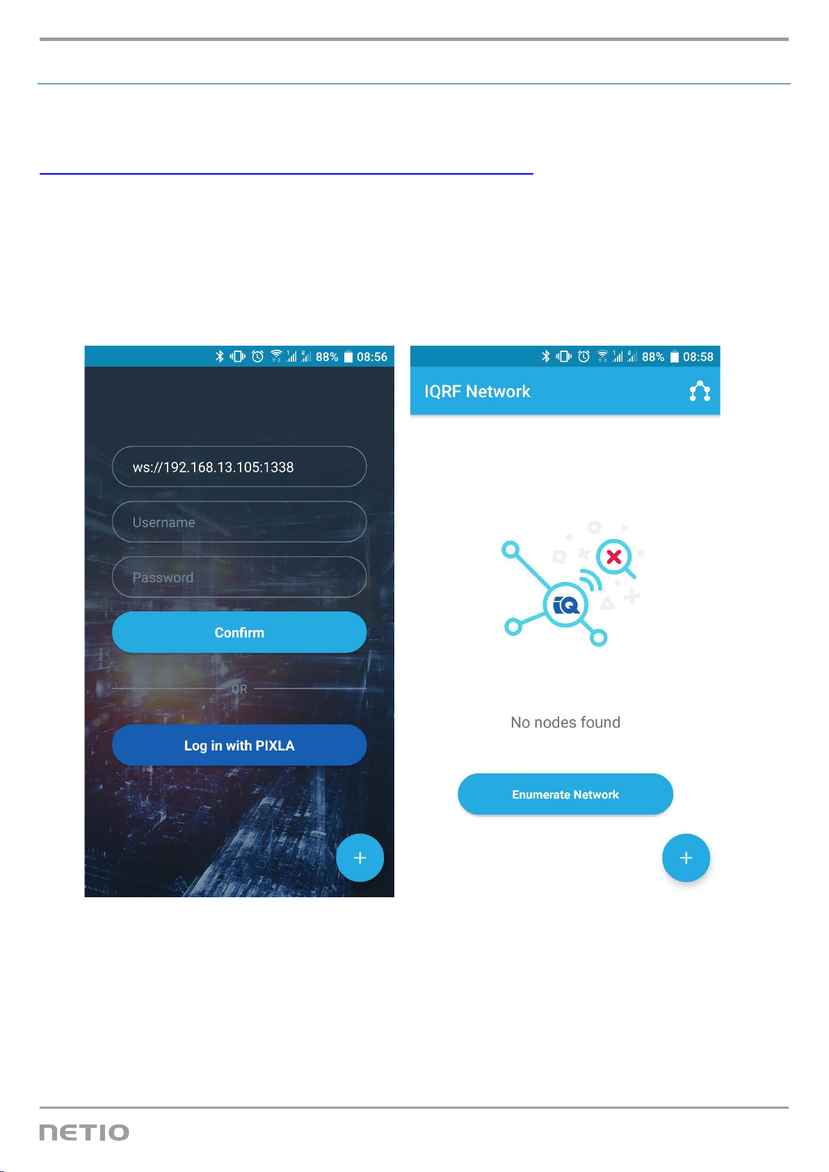
1. When the app is started, it needs the details to connect to the IQRF Interoperable Gateway.
The Gateway must be accessible in the LAN. Websocket is used for the connection.
2. When the connection is successfully established, the current network status is loaded. At the
beginning, the network is empty (“No nodes found”).

5 / 18
www.netio-products.com
Connecting to the IQRF network (Bonding)
Bonding must be started at the device to which the PowerCable IQRF should connect. Most often,
this is the IQRF Gateway. When testing, it could be the IQRF Coordinator controlled with the IQRF
IDE.
A device can be bonded in three ways:
•SmartConnect – using the IQRF Smart Connect code (QR code) shown on the device.
•Local Bonding – using some physical interaction with the device (a button on the PowerCable
IQRF).
•AutoNetwork – automatically connects all available devices with the same network key.
Example: Connecting with the mobile app – SmartConnect
•Connect the app to the IQRF Interoperable Gateway.
•Click the blue circle with a plus symbol in the bottom right-hand corner to add a device into the
network using any of the available methods. To add a device using the SmartConnect method,
select “Smart Connect with QR Code”.
•Point the phone’s camera so that the QR code is in focus and within the indicated area.

6 / 18
www.netio-products.com
The code is scanned and device details are displayed. After confirming, the Smart Connect
procedure starts. The app informs about the progress and the result.
The message about a successful connection also shows the address assigned to the device.
All interoperable devices connected to the network are then listed in the home panel.
7 / 18
www.netio-products.com
Example: Connecting with the IQRF IDE – Local Bonding
1. Connect the module or the USB Gateway that acts as the Coordinator to the IQRF IDE.
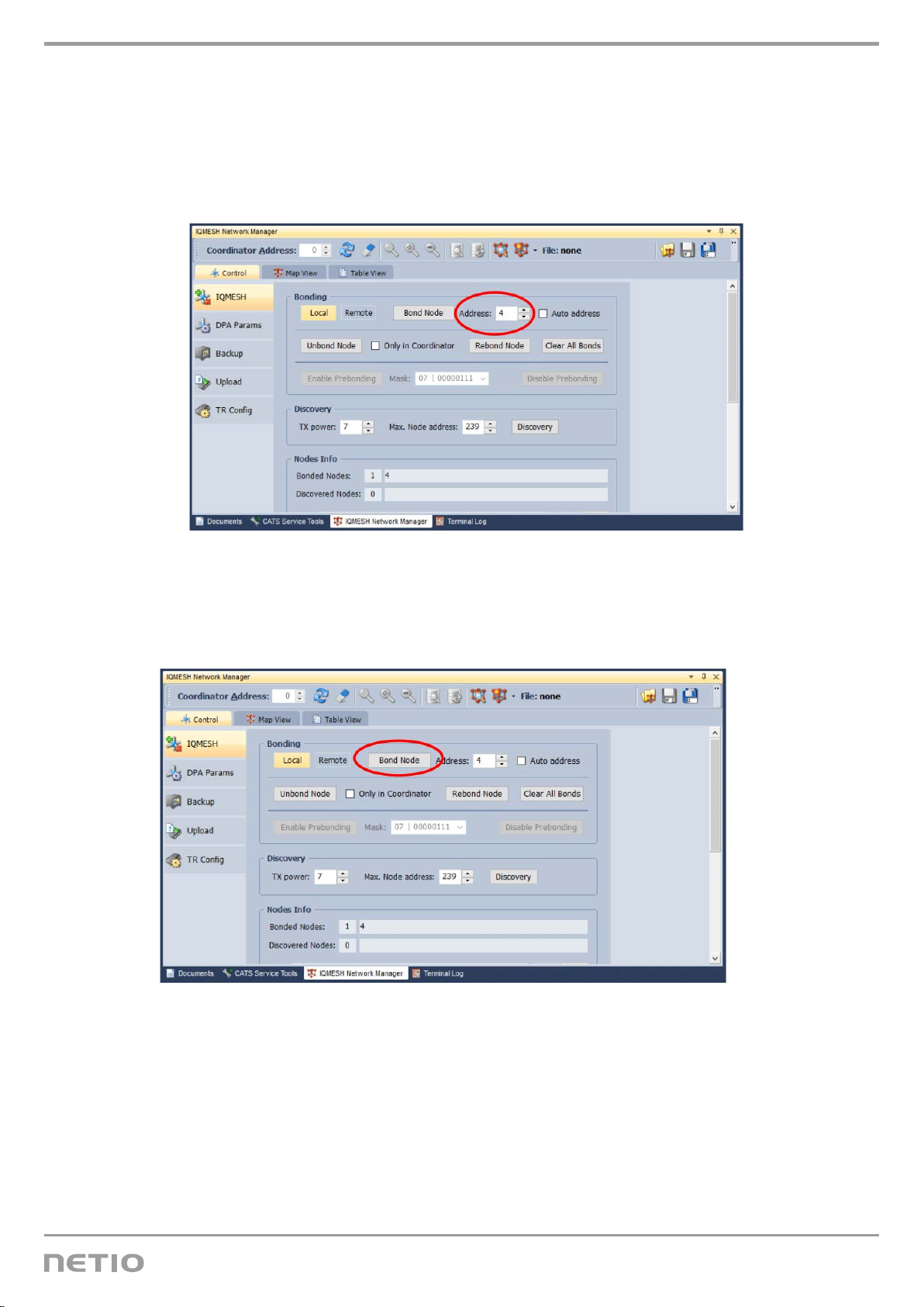
2. In the IQRF IDE, open these windows: Packet Inspector, Terminal, IQMESH Network Manager
3. In the IQMESH Network Manager, go to the Control tab, and enter address 4 in the IQMESH
menu.
4. Click Bond Node
8 / 18
www.netio-products.com
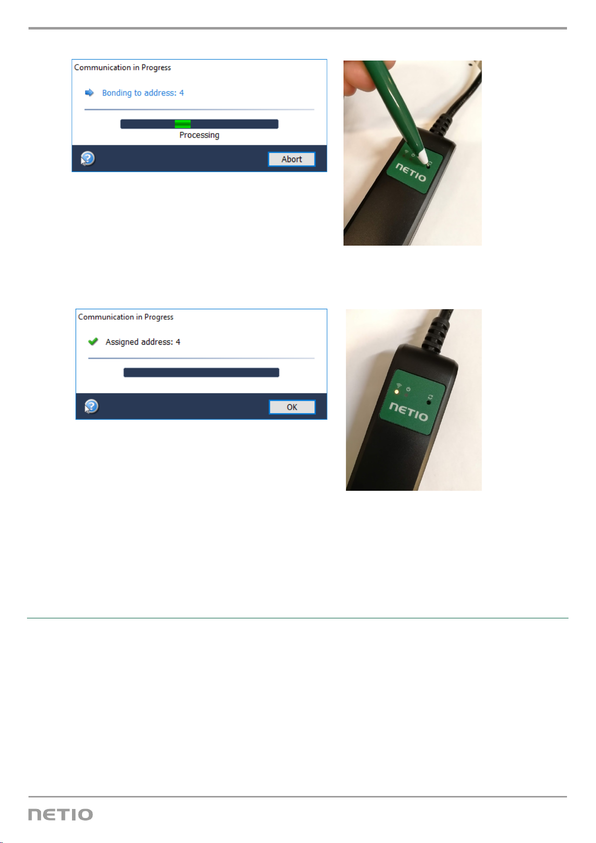
5. While the search is in progress, press the button on the PowerCable IQRF
6. After a successful bonding, a message about the bonding result appears and the yellow LED
lights up on the PowerCable IQRF.
Unbonding from the IQRF network
The device can be unbonded in two ways:
1. By the Coordinator – use the “Unbond Node” function with the selected PowerCable
address, and confirm the unbonding at the remote device, too.
2. By the PowerCable IQRF – unplug the PowerCable IQRF. Press and hold the bonding button
(Reset icon) and plug the device back in. Hold the button pressed until the green LED (Output
icon) lights up, then release immediately. Successful unbonding is indicated by flashing yellow
LED (WiFi icon) = Unbonded status.
9 / 18
www.netio-products.com
Example: Unbonding from the IQRF network in the mobile app
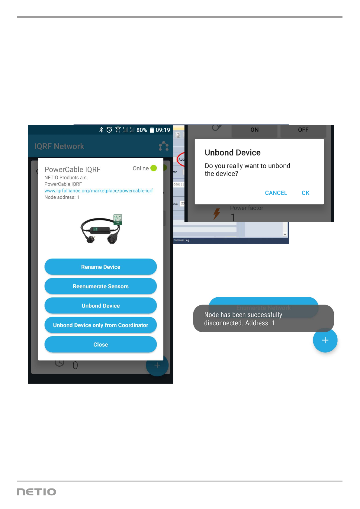
After clicking a particular device in the list, details can be shown or additional actions selected from a
menu.
The “Unbond Device” item removes a device from the network by the coordinator
If the device is unbonded by the PowerCable IQRF, it will show up as Offline. Such a device can be
removed with the “Unbond Device only from Coordinator” function.
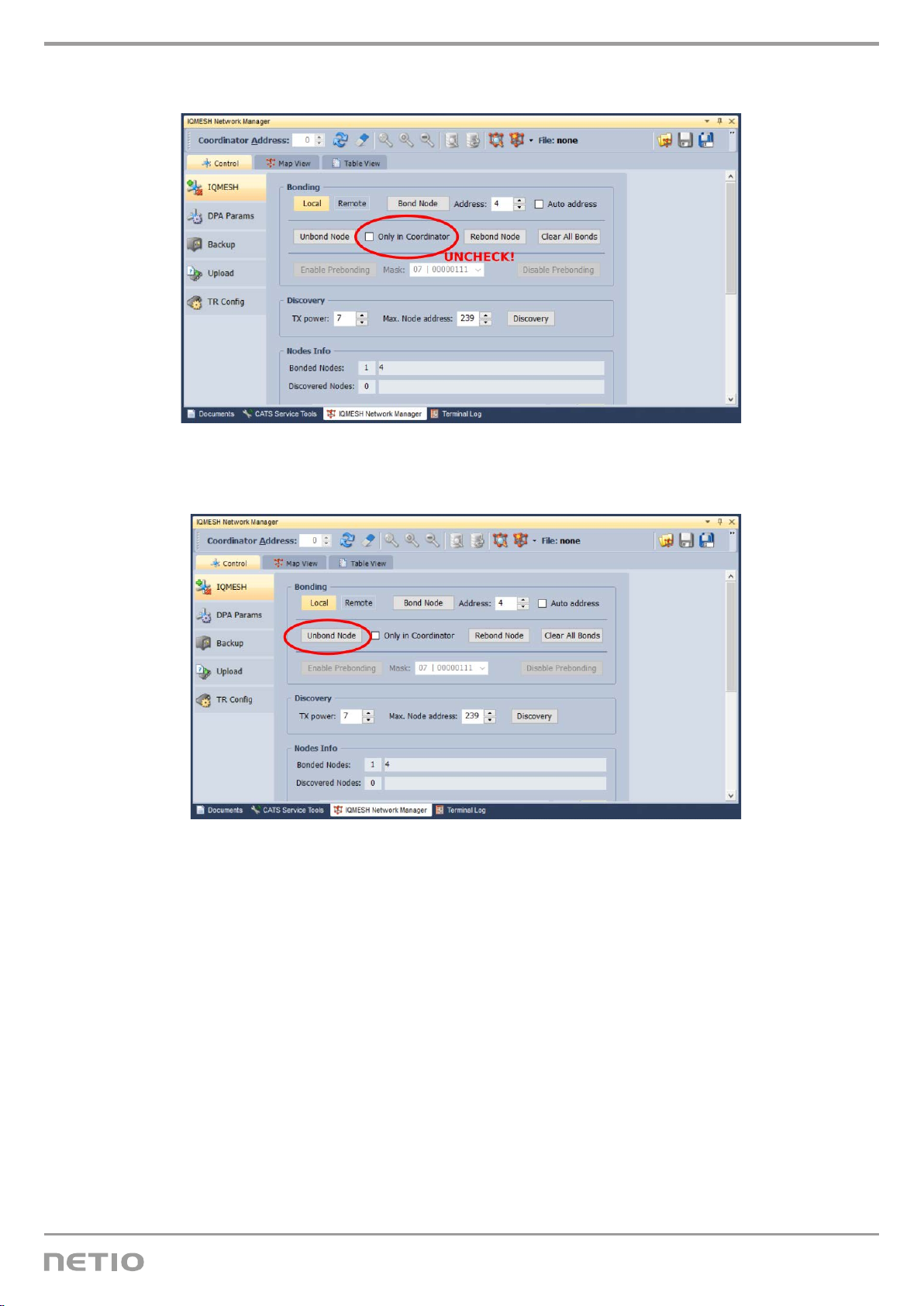
Example: Unbonding from the IQRF network in the IQRF IDE
1. In the IQMESH Network Manager, go to the Control tab, and enter the address of the
PowerCable IQRF to unbond in the IQMESH menu.
For example address 4. Leave the PowerCable IQRF turned on and connected to the 230V
grid!
10 / 18
www.netio-products.com
2. Check “Only In coordinator”.
3. Click Unbond Node and confirm.

11 / 18
www.netio-products.com
Controlling the output
DPA Standard Binary Output
The output of the PowerCable IQRF can be controlled and monitored using the “Standard Binary
Output” function of the DPA protocol. Commands and states conform to this standard.
Documentation according to DPA Interoperable: IQRF-StandardBinaryOutput-V004
https://www.iqrfalliance.org/techdoc_files/IQRF-StandardBinaryOutput_V004.pdf
Output address: 0x01
Example: Switching the PowerCable output on in the mobile app
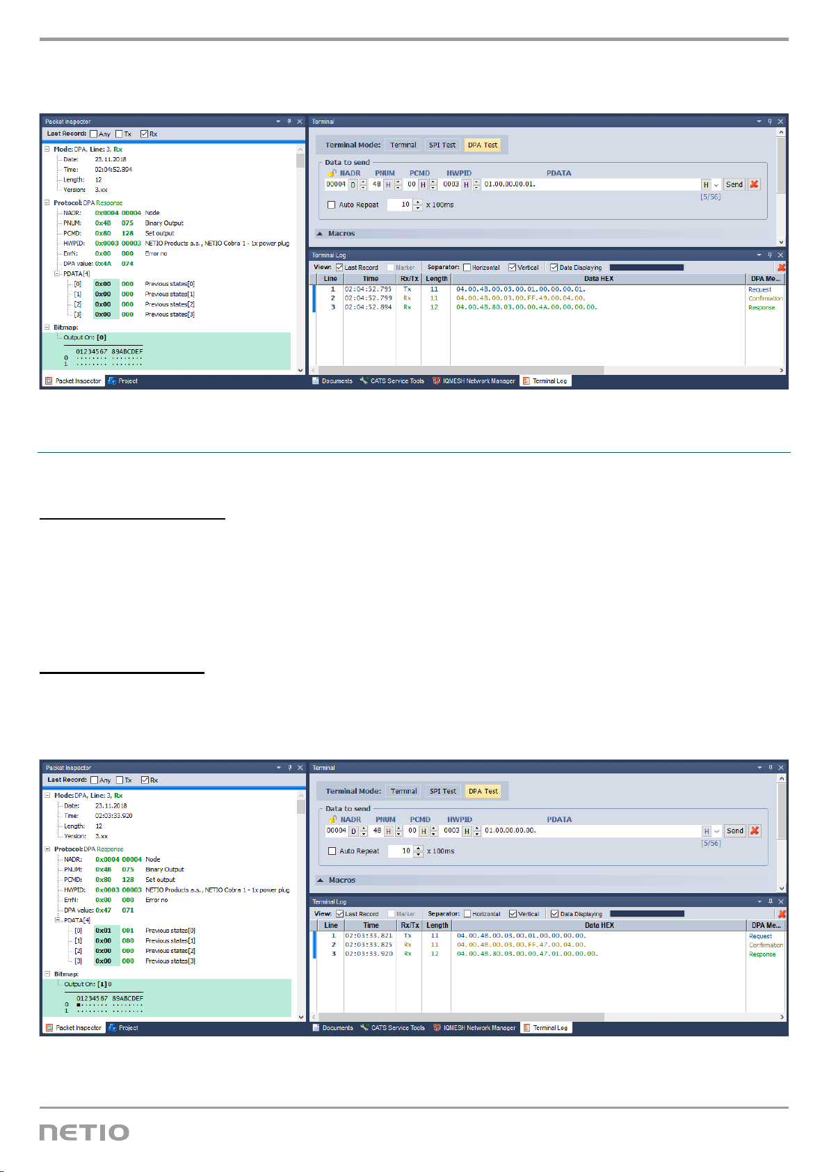
Example: Switching the PowerCable output on in the IQRF IDE
In the IQRF IDE, open these windows: Packet Inspector, Terminal, Terminal Log.
Message header (HEX):
NADR: 0x0004
PNUM: 0x4B
PCMD: 0x00
HWPID: 0x0003
Message data (HEX):
PDATA: 01.00.00.00.01
12 / 18
www.netio-products.com
Response PDATA if the command is correctly received: 04.00.4B.80.03.00.00.4A.00.00.00.00.
(Previous output state: off)
Example: Switching the PowerCable output off in the IQRF IDE
In the IQRF IDE, open these windows: Packet Inspector, Terminal, Terminal Log.
Message header (HEX):
NADR: 0x0004
PNUM: 0x4B
PCMD: 0x00
HWPID: 0x0003
Message data (HEX):
PDATA: 01.00.00.00.00
Response PDATA if the command is correctly received: 04.00.4B.80.03.00.00.47.01.00.00.00.
(Previous output state: on)
13 / 18
www.netio-products.com
Reading the measurements
DPA Standard Sensor
PowerCable IQRF measurements can be controlled and read using the “Standard Sensor” function of
the DPA protocol. Commands and values conform to this standard.
Documentation according to DPA Interoperable: IQRF-StandardSensor-V014
(https://www.iqrfalliance.org/techdoc_files/IQRF-StandardSensor_V014.pdf)
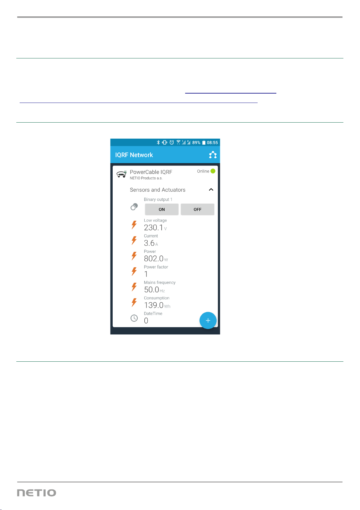
Example: Reading all PowerCable IQRF sensors in the mobile app
Addresses of individual sensors in PowerCable IQRF 901x
Voltage (Sensor 0)
Sensor Type: [0x06] Low Voltage
PDATA:
Current (Sensor 1)
Sensor Type: [0x07] Current
PDATA:
Power (Sensor 2)
Sensor Type: [0x08] Power
PDATA:

14 / 18
www.netio-products.com
Power factor (Sensor 3)
Sensor Type: [0x82] Power Factor
PDATA:
Frequency (Sensor 4)
Sensor Type: [0x09] Mains Frequency
PDATA:
Consumption (Sensor 5)
Sensor Type: [0xA1] Consumption
PDATA:
Date and time when the consumption measurement started (Sensor 6)
Sensor Type: [0xA2] Datetime
PDATA:
Note: The consumption cannot be reset. In this regard, the PowerCable IQRF behaves as a regular
power meter. The date and time refer to the factory reset.
Example: Reading all PowerCable IQRF sensors in IQRF IDE
In the IQRF IDE, open these windows: Packet Inspector, Terminal, Terminal Log.
Message header (HEX):
NADR: 0x0004
PNUM: 0x5E
PCMD: 0x01
HWPID: 0x0003
Message data (HEX):
PDATA: 7F.00.00.00
Response PDATA if the command is correctly received (example):
04.00.5E.81.03.00.00.44.06.BD.0E.07.E6.14.08.AC.13.82.C6.09.64.C3.A1.23.00.00.00.A2.9D.07.C0.
5B.

15 / 18
www.netio-products.com
Example: Reading the electrical current from PowerCable IQRF in the IQRF IDE
In the IQRF IDE, open these windows: Packet Inspector, Terminal, Terminal Log.
Message header (HEX):
NADR: 0x0004
PNUM: 0x5E
PCMD: 0x01
HWPID: 0x0003
Message data (HEX):
PDATA: 02.00.00.00
Response PDATA if the command is correctly received (example):
04.00.5E.81.03.00.00.44.07.DB.14.
Configuring the default power-on state
The Power Cable IQRF supports user-configurable power-on output state. The following options are
available:
•OFF – when the power is restored, the output is always off and can only be switched on with a
command over the IQRF network
•ON – when the power is restored, the output is always switched on (within 2 seconds after
powering up the device), and can be only switched off with a command over the IQRF network
•LAST – when power is disconnected or interrupted, PowerCable IQRF remembers the output
state and restores it within 2 seconds after the power is restored
These states are set over a special service channel using the following commands:

16 / 18
www.netio-products.com
Setting the power-on state to OFF (address 0x0004)
Message header (HEX):
NADR: 0x0004
PNUM: 0x5E
PCMD: 0x40
HWPID: 0x0003
1st message data (HEX):
PDATA: 55.AA.00.0A.01.00.2D
Response PDATA if the command is correctly received: 55 AA 00 05 00 27
2nd message data (HEX):
PDATA: 55.AA.00.09.01.00.2C
Response PDATA if the command is correctly received: 55 AA 00 05 00 27
Setting the power-on state to ON (address 0x0004)
Message header (HEX):
NADR: 0x0004
PNUM: 0x5E
PCMD: 0x40
HWPID: 0x0003
1st message data (HEX):
PDATA: 55.AA.00.0A.01.00.2D
Response PDATA if the command is correctly received: 55 AA 00 05 00 27
2nd message data (HEX):
PDATA: 55.AA.00.09.01.01.2D
Response PDATA if the command is correctly received: 55 AA 00 05 00 27

17 / 18
www.netio-products.com
Setting the power-on state to LAST (address 0x0004)
Message header (HEX):
NADR: 0x0004
PNUM: 0x5E
PCMD: 0x40
HWPID: 0x0003
Message data (HEX):
PDATA: 55.AA.00.0A.01.01.2E
Response PDATA if the command is correctly received: 55 AA 00 05 00 27

18 / 18
www.netio-products.com
EU DECLARATION OF CONFORMITY
Manufacturer:
NETIO products a.s
Address:
U Pily 3/103
143 00 Praha 4, Czech Republic
Product / type:
901x- where “x” stands for the socket/plug type
code:
EFR
F DE
This EU Declaration of Conformity is issued under the sole responsibility of the manufacturer.
Object of this Declaration: “NETIO PowerCable IQRF 901x extension cord controlled and monitored
over the IQRF network”.
The above-mentioned object of this Declaration complies with applicable harmonizing
legislation of the European Union:
•2014/53/EU (CZ no. 426/2016) including addendums
References to applicable harmonized standards or other technical specifications, with which
conformity is hereby declared
•Article 3(1)(a) Protection of health and safety
•Article 3(1)(b) Electromagnetic compatibility
•Article 3(2) Effective and efficient use of radio spectrum
Additional information:
•Test protocol No.: EZÚ 700026-01/06 dated 31st January 2018
•Test protocol No.: EZÚ 700026-01/09 dated 31st January 2018
RoHS:
We hereby declare that the above-mentioned product(s) comply with essential requirements of the
Government Regulation No. 481/2012 Sb. (Directive 2011/65/EU) on the restriction of the use of
certain hazardous substances in electrical and electronic equipment.
The following standards were used in the conformity assessment: EN 50581:2012
Czech Republic, Praha, 18th March 2019 Jan Řehák, Chair of the Board
This manual suits for next models
2
Table of contents
Other Netio Cables And Connectors manuals


Popular Cables And Connectors manuals by other brands


Hall Technologies
Hall Technologies ULTRA-V Series user manual

Tyco Electronics
Tyco Electronics CPC 45 Series instruction sheet

Banner
Banner Plastic Fiber Optic PBT46UC installation instructions

LEGRAND
LEGRAND ON-Q HT2302B quick start guide

Intercontec
Intercontec 615 Series manual

TechLogix Networx
TechLogix Networx TL-DA14-F2 user manual


