manuals.online logo
Brands
  1. Home
  2. •
  3. Brands
  4. •
  5. Banner
  6. •
  7. Cables And Connectors
  8. •
  9. Banner Plastic Fiber Optic PBT46UC User manual

Banner Plastic Fiber Optic PBT46UC User manual

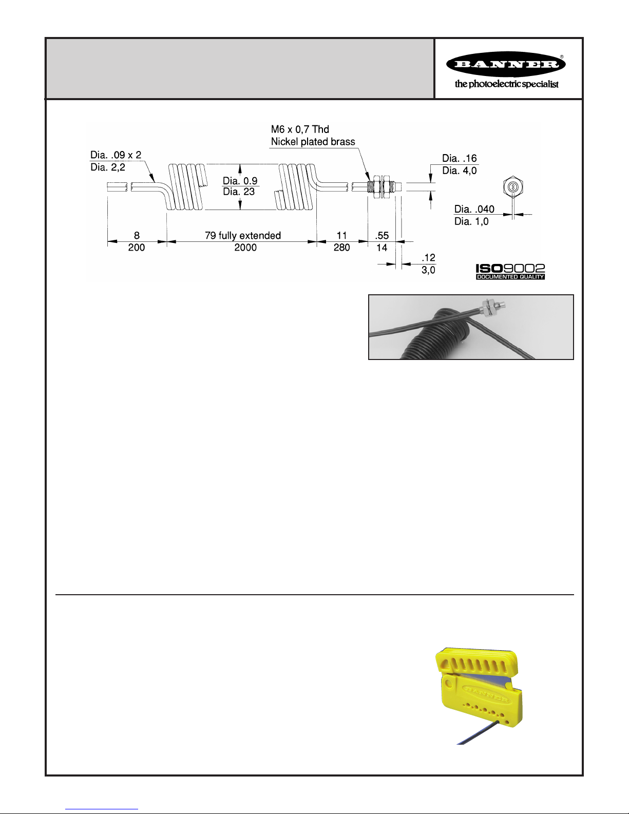
.04" diameter coiled bifurcated fiber with threaded sensing end
Plastic Fiber Optic Assembly model PBT46UC
PBT46UC p/n 26086
This Banner plastic fiber is designed to be cut by the customer to the length required for the application. To
facilitate cutting, a Banner model PFC-1 cutting device is supplied with this fiber. Cut the fiber as follows:
1) Locate the "control end" of the fiber (the unfinished end). Determine the length of fiber required for the
application. At the control end of the fiber, separate the two fibers. Lift the top (blade) of the cutter to
open the cutting ports. Insert one of the control ends through one of the four large cutting ports on the
PFC-1 cutter so that the excess fiber protrudes from the back of the cutter.
2) Double-check the fiber length, and close the cutter until the fiber is cut. Using a different cutting port, cut
the second control end to the same length as the first. Separate the cut ends for a length of 2 to 3 inches
to allow proper attachment to the sensor.
3) Gently wipe the cut ends of the fiber with a clean, dry cloth to remove any contamination.
Do not use solvents or abrasives on any exposed optical fiber. Do not use a cutting port more than once.
The blade may tend to dull after one cut.
SENSING RANGE: A function of the sensor. For further information, see the data
sheet packed with the sensor, or refer to the Banner product catalog.
TEMPERATURE EXTREMES: Temperatures below -30°C will cause embrittlement of
the plastic materials but will not cause transmission loss. Temperatures above +70°C
will cause both transmission loss and fiber shrinkage.
REPEAT BENDING/FLEXING: Life expectancy of plastic fiber optic cable is in excess
of one million cycles at bend radii of no less than the minimum (stated at right) and a
bend of 90 degrees or less. Avoid stress at the point where the cable enters the sen-
sor ("control end") and at the sensing end tip. Coiled plastic fiberoptic assemblies are
recommended for any application requiring reciprocating fiber motion.
OPERATING TEMPERATURE: -30 to +70°C (-20 to +158°F).
CHEMICAL RESISTANCE: The acrylic core of the monofilament optical fiber will be
damaged by contact with acids, strong bases (alkalis) and solvents. The polyethylene
jacket will protect the fiber from most chemical environments. However, materials may
migrate through the jacket with long term exposure. Samples of fiber optic material
are available from Banner for testing and evaluation.
MINIMUM BEND RADIUS OF PLASTIC FIBER: 1.0 inch (25 mm)
CONSTRUCTION:
OPTICAL FIBER: acrylic monofilament
PROTECTIVE JACKET: black polyethylene
THREADED END TIP and hardware: nickel plated brass
Fiber Cutting Information
Additional Specifications
Printed in USA p/n 03433L4B
Model PBT46UC is a bifurcated coiled plastic fiber optic assembly with
an M6 x 0,75mm threaded nickel plated brass sensing end. Coiled plastic
fibers are especially suited to applications requiring repeated flexing (re-
ciprocating motion).
The PBT46UC operates in the diffuse sensing mode. Sensing light is
transmitted and received through the threaded fiber sensing end. Objects
are detected by the light they reflect back through the sensing end. Fiber
core diameter is .04 inch.
The PBT46UC may be used with plastic fiber optic sensors from the following Banner sensor families: D12, OMNI-BEAM, MAXI-
BEAM, VALU-BEAM, Q45, PC44, MINI-BEAM, and ECONO-BEAM. See page 2 for further information.
Description
PFC-2 Cutting Device
Fiber Installation Instructions
Banner Engineering Corp. 9714 Tenth Ave. No., Minneapolis, MN 55441 Telephone: (612) 544-3164 FAX: (612) 544-3213
D12 Series sensors for use
with plastic fiber optic as-
semblies include sensors with
the letters FP in their model
number suffix.
Install the plastic fiber optic assembly(s)
as follows:
1) Prepare the sensor ends of the fibers
(see page 1, bottom).
2) Unlock (slide up) the fiber gripper.
3) Gently insert the prepared plastic fiber
sensor ends into the ports as far as they
will go. Slide the fiber gripper down to
lock.
D12 Series
OMNI-BEAM, MAXI-BEAM,
VALU-BEAM, and Q45 Series
sensors for use with plastic
fiber optic assemblies include
sensors with the letters FP in
their model number suffix.
OMNI-BEAM, MAXI-BEAM, VALU-BEAM, Q45 Series
Install the plastic fiber optic assembly(s)
as follows:
1) Prepare the sensor ends of the fibers
(see page 1, bottom).
2) Loosen the clamp screw on the sensor
face.
3) Follow steps 1-3 in the drawing, right.
MINI-BEAM, ECONO-BEAM
Install the plastic fiber optic assembly(s)
as follows:
1) Prepare the sensor ends of the
fibers (see page 1, bottom).
2) Loosen the clamp screw on the
sensor face.
3) Follow steps 1-3 in the drawing, right.
MINI-BEAM and ECONO-
BEAM sensors for use with
plastic fiber optic assemblies
include sensors with the letters
FP in their model number
suffix.
PC44 Series sensors for use
with plastic fiber optic as-
semblies include sensors with
the letters FP in their model
number suffix.
Install the plastic fiber optic assembly(s)
as follows:
1) Prepare the sensor ends of the fibers
(see page 1, bottom).
2) Raise (liftup) the fiber gripper door.
3) Gently insert the prepared plastic fiber
sensor ends into the ports as far as they
will go. Lower the fiber gripper to
lock.
PC44 Series

Other Banner Cables And Connectors manuals

Banner TCNM-ACBB1 User manual

Banner

Banner TCNM-ACBB1 User manual

Banner SSA-ISD-TCA User manual

Banner

Banner SSA-ISD-TCA User manual

Banner PBT26U User manual

Banner

Banner PBT26U User manual

Banner Plastic Fiber Optic PBT46U User manual

Banner

Banner Plastic Fiber Optic PBT46U User manual

Banner PIF46U User manual

Banner

Banner PIF46U User manual

Banner Plastic Fiber Optic Assembly PBPS26U User manual

Banner

Banner Plastic Fiber Optic Assembly PBPS26U User manual

Banner PLI-A10 User manual

Banner

Banner PLI-A10 User manual

Popular Cables And Connectors manuals by other brands

igus readychain installation manual

igus

igus readychain installation manual

Kramer VM-10H2 user manual

Kramer

Kramer VM-10H2 user manual

General Pump DHR50100D operating instructions

General Pump

General Pump DHR50100D operating instructions

National Instruments IMAQ A8055 installation guide

National Instruments

National Instruments IMAQ A8055 installation guide

Philips SWV2197W/10 Specifications

Philips

Philips SWV2197W/10 Specifications

ProFlo PFSAVB01CP manual

ProFlo

ProFlo PFSAVB01CP manual

Paradyne HotWire 5034 installation instructions

Paradyne

Paradyne HotWire 5034 installation instructions

Philips SJM2111 Specification sheet

Philips

Philips SJM2111 Specification sheet

Philips SWV3441 Specifications

Philips

Philips SWV3441 Specifications

Belden GDS Series Assembly instructions

Belden

Belden GDS Series Assembly instructions

PureEdge Lighting NSM-XP Series installation instructions

PureEdge Lighting

PureEdge Lighting NSM-XP Series installation instructions

PowerBridge ONE-PRO-6 manual

PowerBridge

PowerBridge ONE-PRO-6 manual

PROception proCOM21TS installation instructions

PROception

PROception proCOM21TS installation instructions

Philips SWV2516W Specifications

Philips

Philips SWV2516W Specifications

Dormont Blue Hose Installation & operating instructions

Dormont

Dormont Blue Hose Installation & operating instructions

Siemens SIMATIC 6ES7158-3MU10-0XA0 Hardware Installation and Operating Manual

Siemens

Siemens SIMATIC 6ES7158-3MU10-0XA0 Hardware Installation and Operating Manual

ADTRAN 1442520G1 quick start guide

ADTRAN

ADTRAN 1442520G1 quick start guide

Avermedia C039 manual

Avermedia

Avermedia C039 manual

manuals.online logo
manuals.online logoBrands
  • About & Mission
  • Contact us
  • Privacy Policy
  • Terms and Conditions

Copyright 2025 Manuals.Online. All Rights Reserved.