Netio PowerCable 101 Series User manual

PowerCable xxx
101x
MANUAL
-PowerCable Modbus 101x
-PowerCable MQTT 101x
-PowerCable REST 101x
29.4.2020

2
Table of Contents
Introduction .......................................................................................................... 4
1Safety notices .................................................................................................. 4
2General characteristics ....................................................................................... 4
3PowerCable xxx ................................................................................................ 6
4Specifications .................................................................................................. 8
4.1 Specifications of different socket types...................................................... 9
4.2 Features ..........................................................................................11
4.3 Drawings..........................................................................................13
4.4 Device description ..............................................................................14
4.5 LED and button functions ......................................................................15
4.6 Minimum system requirements (for configuration)........................................15
4.7 Package contents ...............................................................................16
5Configuration and control ...................................................................................17
5.1 Connecting PowerCable to a local WiFi (AP Mode) ........................................17
5.2 NFC installation in 60 seconds ................................................................20
5.2.1 NETIO Mobile2 for Android ........................................................20
5.3 Detecting and configuring the IP address ...................................................20
5.4 Login to device web ............................................................................22
5.5 Restoring factory defaults .....................................................................23
5.6 Controlling the output manually..............................................................24
6Web interface .................................................................................................25
6.1 Outputs ...........................................................................................25
6.1.1 Outputs - Energy measurements .................................................26
6.1.2 Outputs - General ..................................................................27
6.2 M2M API Protocol Actions ......................................................................29
6.3 Cloud..............................................................................................30
6.4 Users ..............................................................................................33
6.5 Settings ...........................................................................................35
6.5.1 Wi-Fi..................................................................................35
6.5.2 Network Configuration ............................................................36
6.5.3 Date / Time .........................................................................38
6.5.4 Firmware.............................................................................38
6.5.5 System................................................................................41
6.6 Log.................................................................................................43
7PowerCable REST 101x.......................................................................................44
7.1 Overview .........................................................................................44
7.2 M2M API Protocol – XML (REST M2M API).....................................................45
7.3 M2M API Protocol – JSON (REST M2M API) ...................................................49
7.4 M2M API Protocol – URL-API (REST M2M API)................................................53
7.5 M2M API Protocol – SNMP.......................................................................56
8PowerCable Modbus 101x ...................................................................................59
8.1 Overview .........................................................................................59
8.2 M2M API Protocol – Modubus/TCP ............................................................60
8.3 M2M API Protocol – Telnet .....................................................................64
8.4 M2M API Protocol – SNMP.......................................................................68
9PowerCable MQTT 101x......................................................................................69
9.1 Overview .........................................................................................69
9.2 M2M API Protocol – MQTT-flex ................................................................70
9.3 M2M API Protocol – Netio Push ................................................................73
9.4 M2M API Protocol – SNMP.......................................................................74
10 PowerCable OEM DevKit 101x...............................................................................75
10.1 Overview .........................................................................................75
10.2 OEM – custom modifications (customizations)..............................................76
11 NETIO products overview....................................................................................77

3

4
Introduction
Thank you for purchasing this product of NETIO products a.s. Before using your product, please read
this
User Manual
(MAN) and the included
Quick Installation Guide (QIG)
to avoid problems with
incorrect installation or use.
Caution:
The product works with mains voltage. Mishandling may damage it or result in injury or death.
1Safety notices
1. The manufacturer is not liable for any damage caused by incorrect use of the device or by
operating it in an unsuitable environment.
2. The device is not rated for outdoor use.
3. Do not expose the device to strong vibrations.
4. Unauthorized modifications may damage the device or cause a fire.
5. Protect the device from liquids and excessive temperatures.
6. Make sure the device does not fall.
7. Only electrical appliances approved for use in the electrical network may be connected to the
device.
8. Do not connect multiple devices in series.
9. The cable plug must be easily accessible.
10. The device is completely switched off only when unplugged from the wall socket.
11. If the device malfunctions, disconnect it from the electrical power supply and contact your
vendor.
2General characteristics
One metered and controlled 110/230V output
WiFi interface: 802.11 b/g/n; 2.4GHz (secured / unsecured)
WiFi encryption: WEP, WPA, WPA2
AP mode for connecting the device to a local WiFi network (network selected from a list)
Button to activate AP mode
Output state can be toggled with the On/OFF button (press 3 times)
Built-in web server for device configuration and control
Password-protected login into device configuration
Electricity consumption metering (6 parameters): [V, Hz, A, W, Wh, TPF]
Measurement accuracy <1%

5
ZCS (Zero Current Switching)
IOC (Independent Output Control)
PowerUp state - (ON / OFF / LAST)
1.2m cable
Overvoltage protection
Operating temperature range: -20°C to +65°C
Supported protocols: DNS, NTP, DHCP, HTTP
Supported M2M protocols:
PowerCable Modbus 101x: Modbus/TCP, Telnet, SNMP
PowerCable MQTT 101x: MQTT, Http(s) Push, SNMP
PowerCable REST 101x: XML API, JSON API, URL API, SNMP

6
3PowerCable xxx
PowerCable Modbus 101x PowerCable REST 101x PowerCable MQTT 101x
Overview of types according to the supported M2M protocols
Type / Protocol
PowerCable
Modbus 101x PowerCable
REST 101x PowerCable
MQTT 101x
Web interface Yes Yes
Yes
Telnet Yes -
-
Modbus/TCP Yes -
-
URL API -Yes
-
XML API -Yes
-
JSON API -Yes
-
MQTT-flex --
Yes
Netio Push JSON --
Yes
Netio Push XML --
Yes
SNMP v1 Yes Yes
Yes
PowerCable
Modbus 101x PowerCable
REST 101x PowerCable
MQTT 101x
NETIO Cloud Yes Yes
Yes
NETIO Mobile2 Yes Yes
Yes

7
Overview of models according to the electrical socket type
Model
Variant Output socket Input plug Voltage Max.
current Max.
load
101F DE Type F
E/F (CEE 7/7)
230V ~
16
A
3600
W
101E F
R
Type E
E/F (CEE 7/7)
230V ~
16
A
3600
W
101J CH Type J
Type J
230V ~
10
A
2300
W
101S IEC-320 C13/C14 IEC-320 C13
IEC-320 C14
110/230V ~
10
A
2300
W
101B US Type B
Type B
110V ~
15
A
1600
W
101G U
K
Type G
Type G
230V ~
13
A
3000
W

8
4Specifications
Power
101E, 101F: 230V~; 50Hz; 16A
101J: 230V~; 50Hz; 10A
101S: 110/230V~; 60/50Hz; 10A
101G: 230V~; 50Hz; 13A
101B: 110V~; 60Hz; 15A
Switched outputs
101E, 101F: 230V~; 50Hz; 16[8]A; max. 3600W
101J: 230V~; 50Hz; 10[8]A; max. 2300W
101S: 110/230V~; 60/50Hz; 10[8]A; max. 2300W
101G: 230V~; 50Hz; 13[8]A; max. 3000W
101B: 110V~; 60Hz; 15[8]A; max. 1600W
Surge protection Type 3 (CAT III)
Internal consumption Max 1W
Output relay
Micro-disconnection (µ) (resistive load)
1E5 switching cycles, max. 1.5kV pulse voltage
Switch heat and fire resistance class 1
Interfaces
PowerCable xxx 101x
1x Wi-Fi 802.11b/g/n 2.4 GHz (internal antenna)
with WEP/WPA/WPA2
Environment
IP30, protection rating = class 1
Operating temperature -10 .. 65°C (6A load = max. 63°C,
10A = max. 50°C, 16A = max. 30°C)
Device rated for pollution degree 2.
Designed for continuous operation in altitudes up to 2000m.
No additional cooling required.
Caution
The device is not designed to power appliances with a high inrush
current.
Do not connect several devices in series.
The device is safe only when completely disconnected from the
electrical network. The cable plug serves as the disconnection means
and must be easily accessible.
The electrical socket must be earthed and protected with a circuit
breaker rated at 16A or less.
9
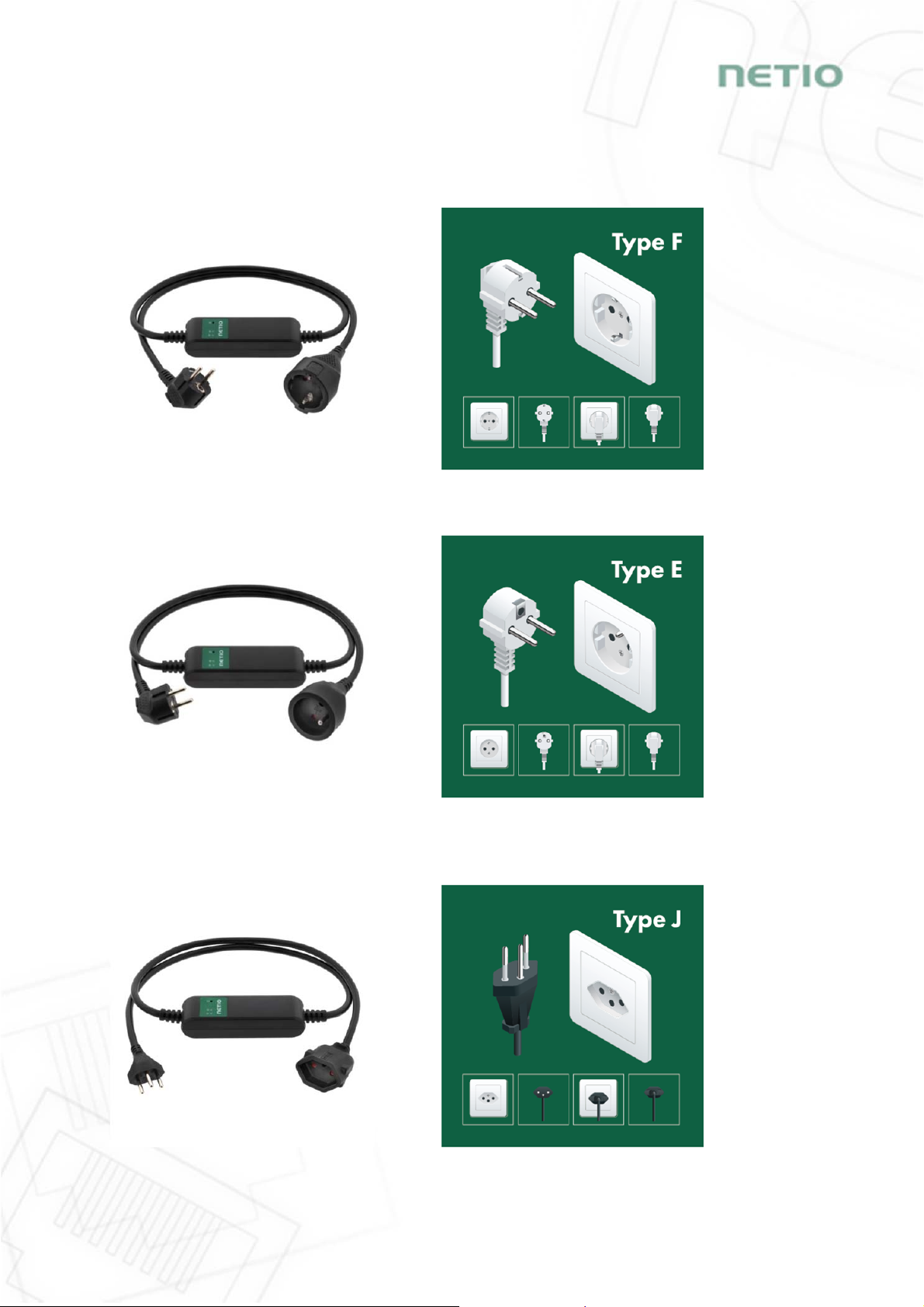
4.1 Specifications of different socket types
NETIO products a.s. supplies the PowerCable xxx 101x in several variants with different
electrical plug/outlet types.
Figure 1 - PowerCable xxx 101F
(DE–schuko - Type F)
Figure 2 - PowerCable xxx 101E
(FR –Type E)
Figure 3 - PowerCable xxx 101J
(CH –Type J)
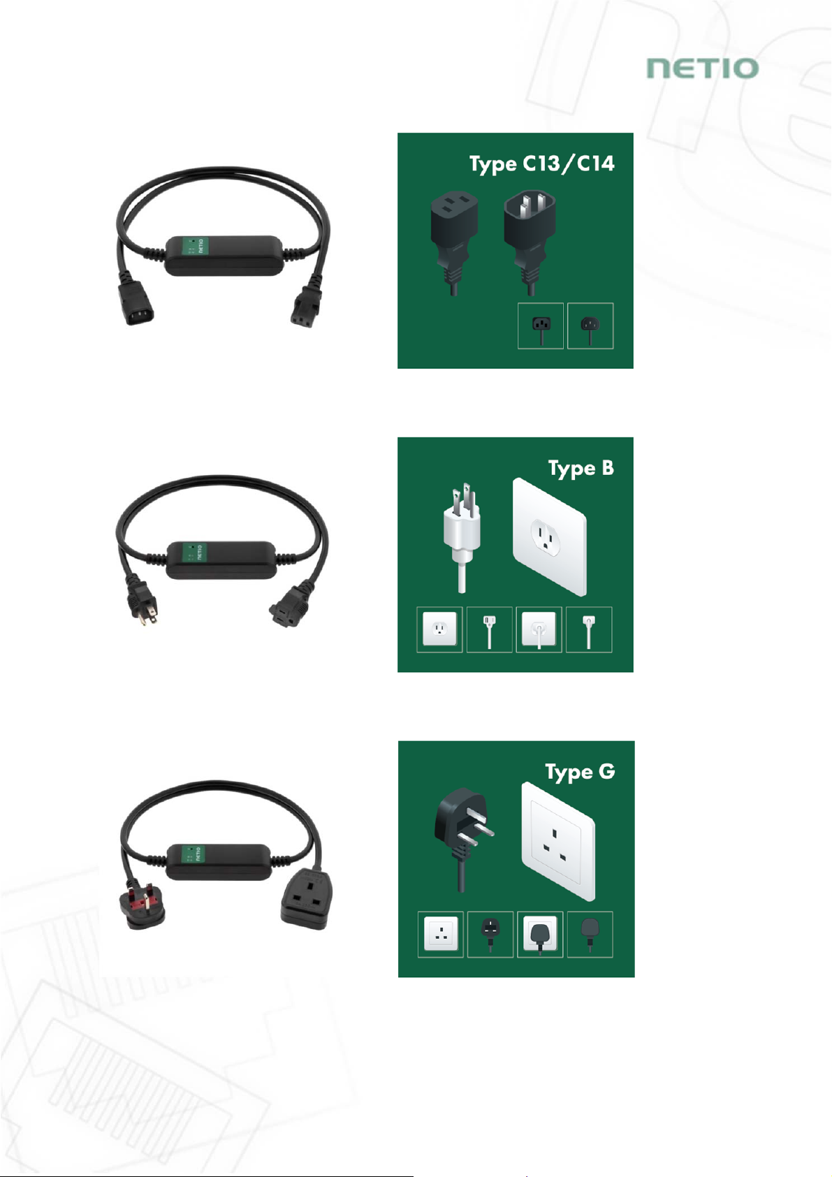
10
Figure 4 - PowerCable xxx 101S
(IEC-320 C13/C14)
Figure 5 - PowerCable xxx 101B
(US –Type B)
Figure 6 - PowerCable xxx 101G
(UK –Type G)

11
4.2 Features
ZCS (Zero Current Switching)
ZCS (Zero Current Switching) function ensures that the relay contact is closed
at the moment of zero voltage and opened at the moment when zero current
flows through it.
Closing and opening at these exact moments has a number of advantages:
The negative effects of inrush current on the lifetime of the relay in the
NETIO device are significantly reduced.
Reduced probability of a circuit breaker tripping in the circuit branch
where the appliance with a high inrush current is connected.
Significantly improved lifetime of switching supplies in appliances that are connected to the
socket (especially in case of frequent switching on and off).
Significantly reduced electromagnetic interference caused by repeated switching on and off.
Zero current switching (ZCS) significantly improves the lifetime of the PowerCable and the
connected end devices. This function is particularly important in case of frequent switching.
IOC (Independent Output Control)
Independent Output Control function of the PowerCable uses an independent
system that ensures a stable operation of the output even if the main system
is being restarted, updated, or is booting.
Thanks to IOC, the controlled output can power devices that, for technical
reasons, must be powered without interruption (such as servers). The output
control is completely independent from the WiFi or LAN communication
subsystem.
PowerUp State
The PowerUp State parameter (sometimes also called Cold start) defines the
behavior of the 110/230V power output during the first milliseconds to seconds
after powering up the device, before the LAN/WiFi communication with a
master system is established.
For some applications, it is important to set the correct state of a power
output immediately after power is turned on (or restored). With servers in
particular it is important to avoid undesired momentary switching.
Possible settings for PowerCable
- On
- Off
- LAST state restores the last state before the power was disconnected
12
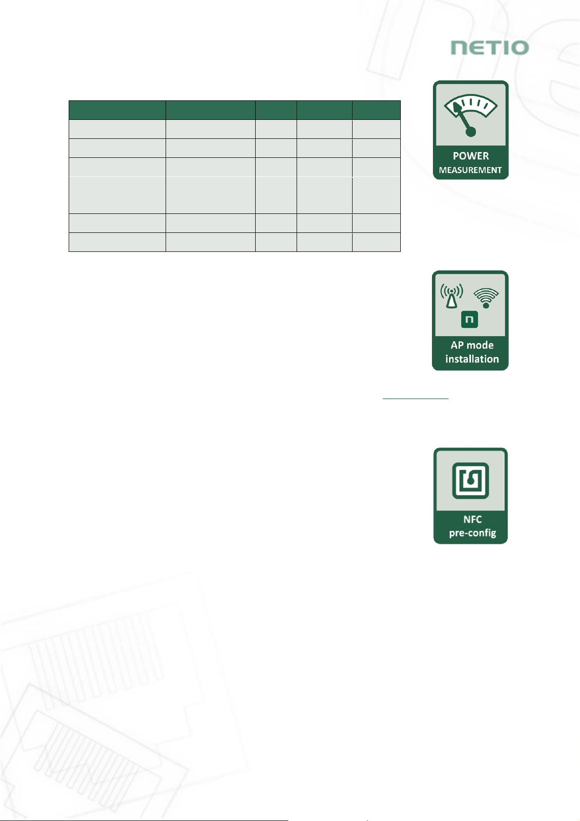
Electrical measurements
PowerCable measures relevant electrical parameters.
Parameter Range Units
Resolution
Accuracy
Voltage 90,0 – 250,0 V
0,1
<1%
Frequenc
y
45,0 – 65,0 Hz
0,1
<1%
Current 0,005 – 16,000
A
0,001
<1%
TPF
(True Power Factor) 0,00 – 1,00 - 0,01 <1%
Output power 0 – 3600 W
1
<1%
Consumption 0 - 4294967296
Wh
1
<1%
Quick WiFi connection setup (AP mode installation)
NETIO PowerCable creates a WiFi network that you connect to with your PC
or mobile phone.
It then scans for WiFi networks in the vicinity, and lets you choose from a
list and type the password.
NETIO PowerCable then confirms the connection to the network and
displays the assigned IP address.
NETIO PowerCable devices can be discovered in the LAN using the NETIO Discover tool.
NFC Preconfig
PowerCable can be pre-configured using NFC even without being switched on.
This require a mobile phone with Android system, NFC function and mobile
application „NETIO Mobile 2“.
The settings configured over NFC will be applied when the device is powered on.
In this way, it is possible to configure or show:
Set SSID and password for connecting to WiFi
Show assigned IP address in DHCP mode
For authentication, the existing password to the web administration “admin” account is used
(default “admin” / “admin”).
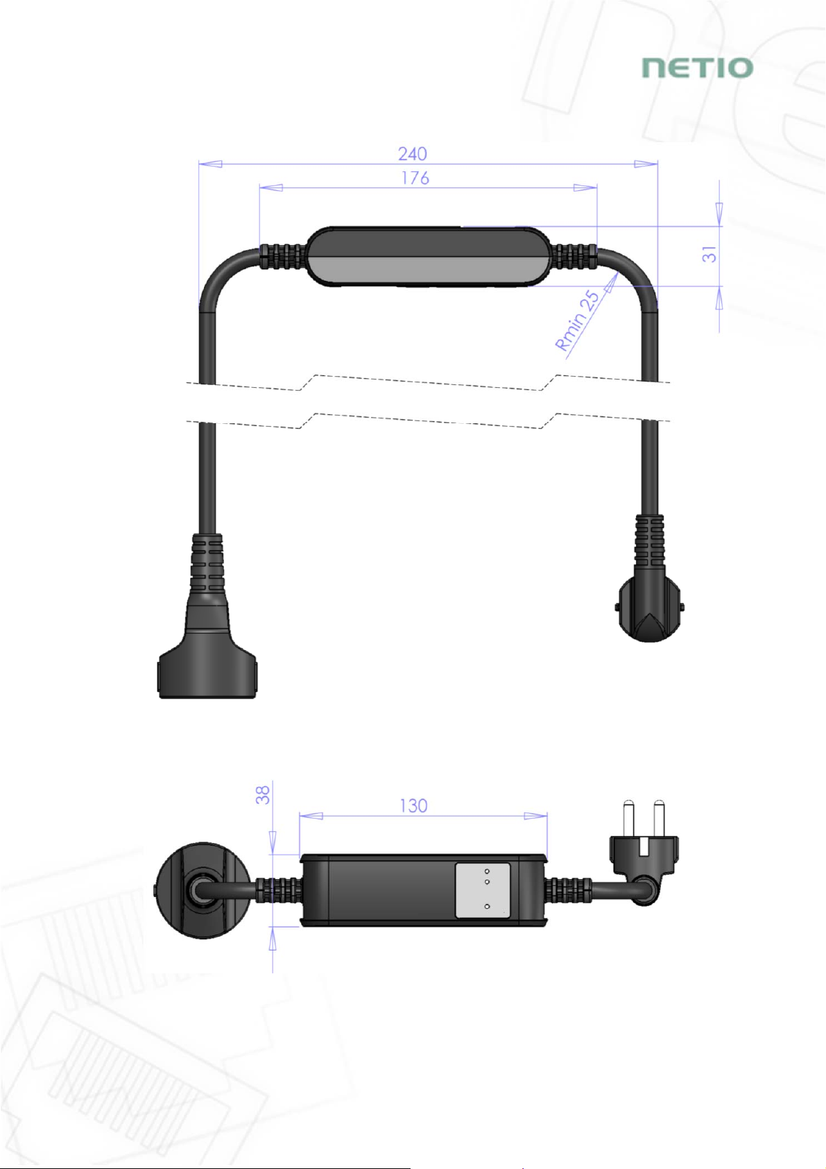
13
4.3 Drawings
Figure 7 – PoweCable xxx 101x side view
Figure 8 – PoweCable xxx 101x top view
14
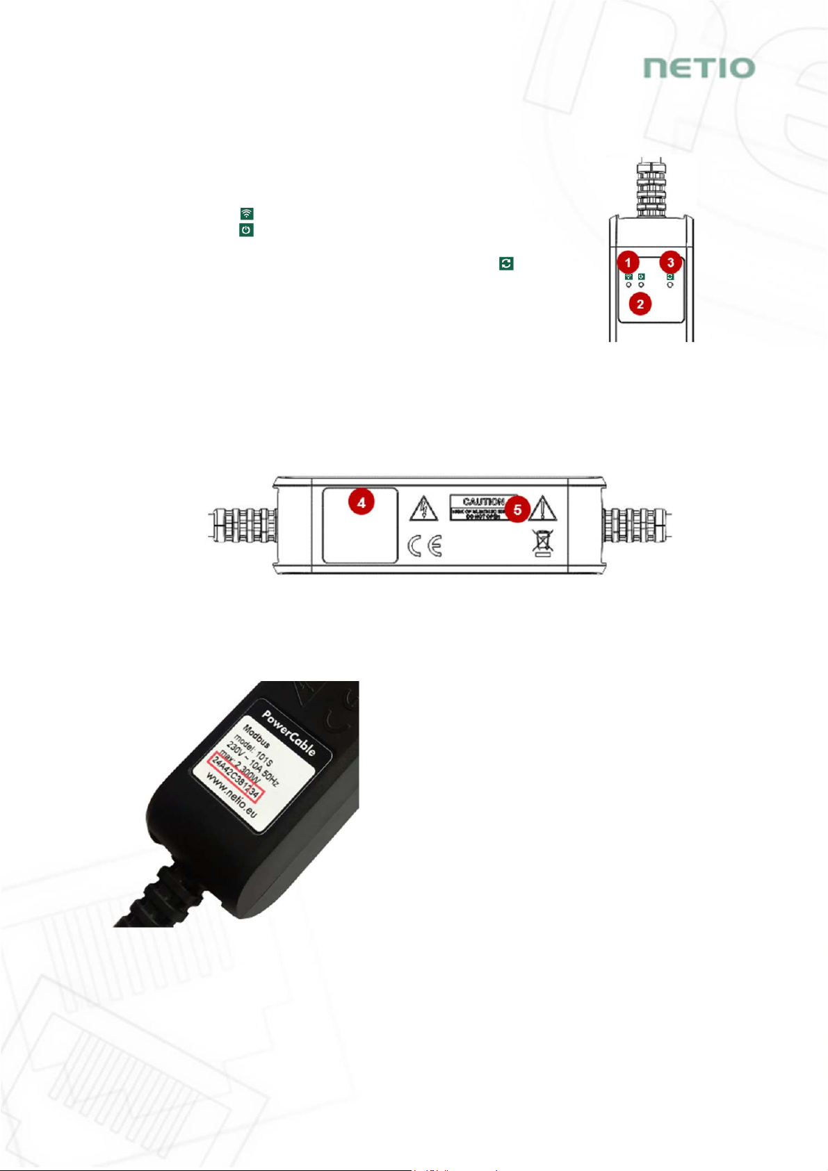
4.4 Device description
1. Status LED (yellow)
2. Output LED (green)
3. Button – to press, a thin object is needed (may be conductive)
4. Type plate – indicates the device model, electrical rating, maximum switching
power and serial number (fig. 11)
5. Warning: Do not open the device – risk of electric shock!
Rear view
Figure 10 – PoweCable xxx 101x bottom view
Figure 11 – PoweCable xxx 101x type plate
SN on the type plate
----------xx
24A42C381234
WiFi network:
PowerCable-AP-xx
PowerCable-AP-34
Front view
Figure 9
–
PoweCable xxx 101x
top view

15
4.5 LED and button functions
Button functions
Controlling
the output Press 3x within 1 to 5 seconds to switch the output.
AP mode
activation
Press and hold for 10 seconds in the standard operating mode.
Hold until the yellow LED (1) starts flashing rapidly.
The AP mode is activated, making it possible to connect to the device and change the
WiFi network to which it should connect.
Restoring
factory
defaults
Turn the device off, press and hold the button and turn the device on. Hold the button
pressed for at least 10 seconds. The device is reset to factory defaults and the AP mode
is activated (green LED flashes rapidly for 1 second, then yellow LED starts flashing
rapidly).
LED indicators
Status
LED (1)
Yellow
Off No WiFi connection
On WiFi connected
Rapidly flashing
& red is off AP mode
Slowly flashing
& red is off Restoring WiFi connection/
Waiting for DHCP
3 fast flashes every second
& red is off Locate function – for one minute after enabling in
the web administration
Red Flash Activity (command received over M2M)
Output
LED (2) Green
Off Output relay open
On Output relay closed
Quick flashing for 1sec “Load to defaults & AP mode” activated
All
LEDs Yellow,
red, green Shortly on During system boot (e.g. after powering up or
rebooting the device)
4.6 Minimum system requirements (for configuration)
A device with an Internet browser (Firefox, Chrome, Safari, Microsoft Internet Explorer, Opera, Mozilla
etc.) that has JavaScript and cookies enabled.

16
4.7 Package contents
- NETIO PowerCable product
- Quick Installation Guide (QIG)
Figure 11a – PoweCable xxx 101x package
17
5Configuration and control
5.1 Connecting PowerCable to a local WiFi (AP Mode)
Plug the NETIO PowerCable into the electrical network. When the device is powered up for the
first time, it enters the “AP mode” that enables basic configuration – selection of a WiFi
network to which the device will connect (yellow LED flashes rapidly).
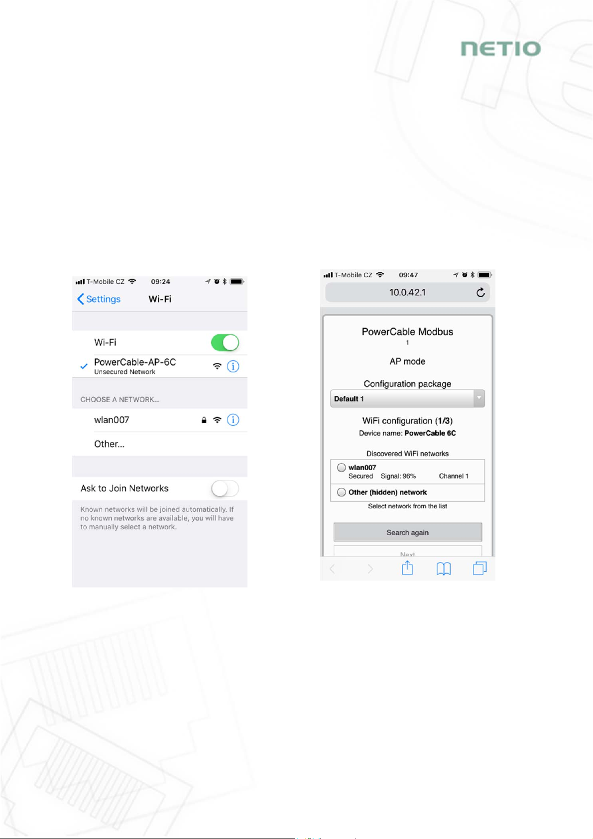
On a computer, tablet or smartphone, display available WiFi networks and connect to the
unsecured “PowerCable-AP-xx” network (Figure 12).
Device configuration page should open automatically. If not, open a web browser and enter
http://10.0.42.1 You will see NETIO PowerCable WiFi configuration page. (Figure 13).
Figure 12 – Connecting to PowerCable AP Figure 13 – Web Interface in AP mode
18
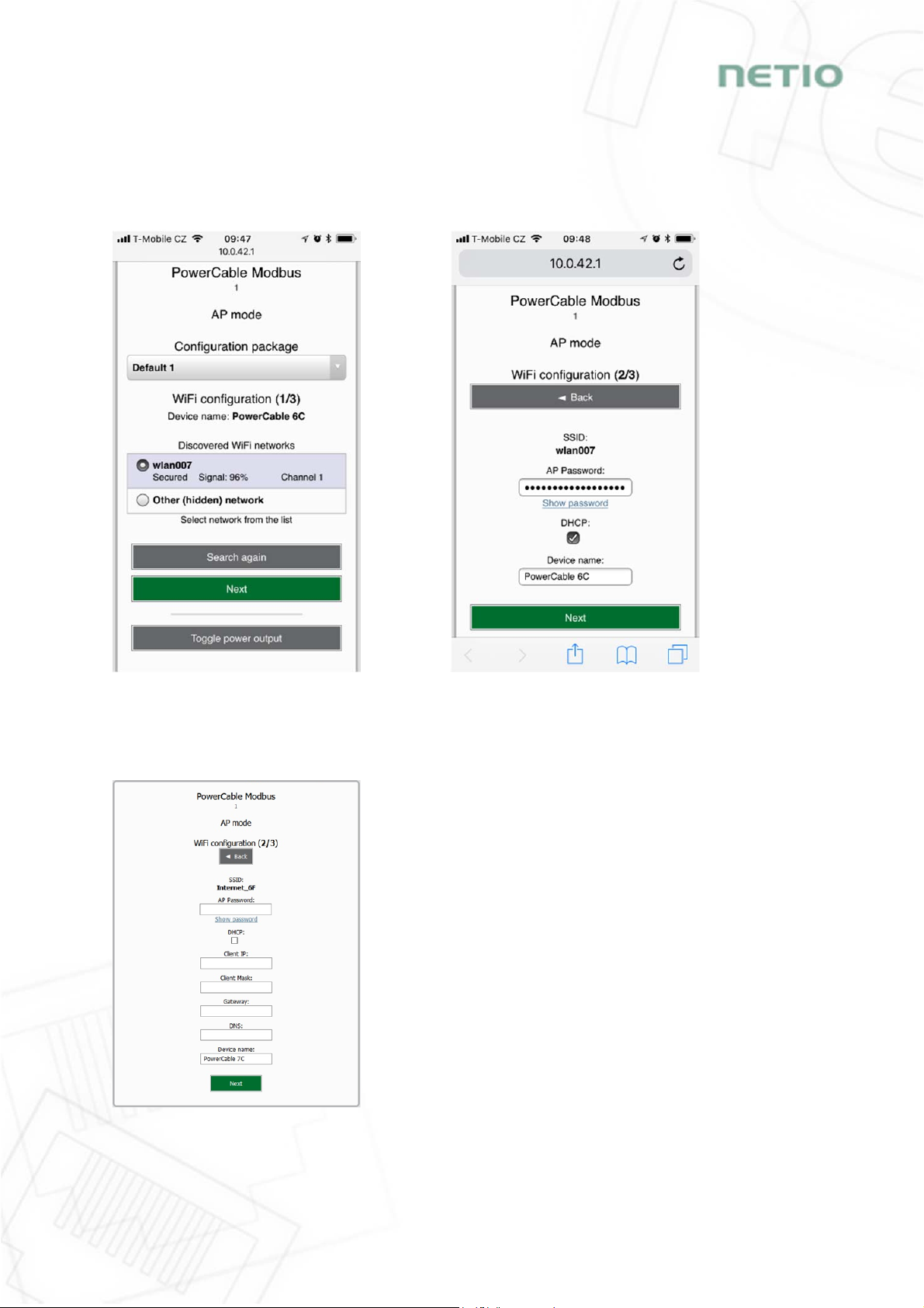
Select your network in the list of detected networks and click “Next” (Figure 14).
Enter the password for the selected WiFi network. You may also change the device name. If
your network does not use DHCP, unselect this option and manually enter the IP address and
other network parameters (Figure 16; for experts only). Click “Next” to confirm (Figure 15).
Figure 14 –Network selection in AP mode Figure 15 – Connecting to Wi-Fi in AP mode
If you do NOT use a DHCP server in your network, set the
following parameters:
AP Password – password for the network to which the
PowerCable will be connected
Client IP – IP address in your network address range
Client mask – network mask for your network
Gateway – gateway for your network
DNS – DNS server for your network or a public DNS, e.g.
8.8.8.8
Device name – specify a name under which the
PowerCable will be visible in the local network
For more information, see chapter 5.6 Network Configuration
Figure 16 – Configuring the network IP parameters
19
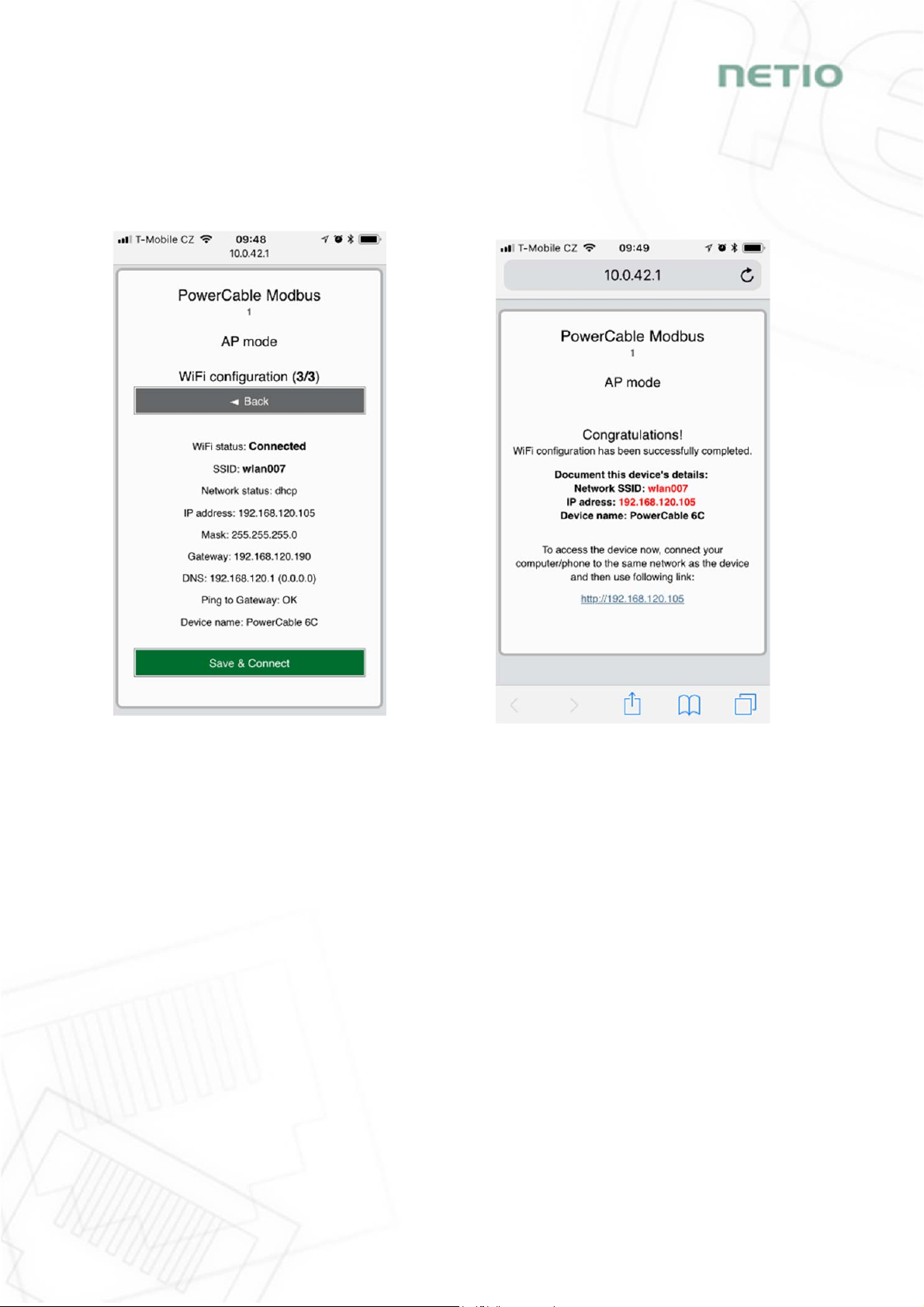
A page with the connection result is displayed. If it shows “WiFi status: Connected“, check the
network parameters and then click “Save&Connect” to save the configuration (Figure 17). The
device then exits the AP mode, connects to the selected WiFi network, and displays a network
configuration summary page (Figure 18). WiFi connection is indicated with the yellow LED.
Figure 17 – Configured Wi-fi parameters Figure 18 – Network connection info

20
5.2 NFC installation in 60 seconds
NFC (Near Field Communication) is a technology supported by some mobile phones (and tablets).
Using a mobile phone with NFC support and the NETIO Mobile 2 app, even a device that is powered
off can be configured. The device will apply the new configuration as soon as it is powered on.
For example:
NFC can be used to configure the WiFi connection parameters (network SSID + password) in the
PowerCable MQTT 101x. When the PowerCable is powered on, it automatically connects to the
specified WiFi network.
NFC and the mobile app can be used to find out the IP address assigned to the installed WiFi
device.
For authentication NFC config, the existing password to the web administration “admin” account is
used (default “admin” / “admin”).
5.2.1 NETIO Mobile2 for Android
NETIO Mobile2 application is for control NETIO devices produced
after 2016.
Features:
Install NFC enabled NETIO devices
Switch On / Off each power socket on local network.
Show power consumption on each power output (if
supported).
Searching NETIO devices in local network
https://play.google.com/store/apps/details?id=cz.netio.netio
5.3 Detecting and configuring the IP address
If you have followed the instructions in the previous chapter, you know the PowerCable’s IP
address, whether it was assigned by a DHCP server or configured manually. If you forgot the IP
address, or if you have received a pre-configured device, you will need to find out its IP address.
Use Windows based NETIO Discover utility, available for download at http://www.netio-
products.com/en/software/netio-discover.
Depending on your operating system, choose the .exe file (Windows) or the .jar file (Linux or Mac).
To run the .jar file, JAVA RE is needed. It is available at: www.java.com
This manual suits for next models
21
Table of contents
Other Netio Cables And Connectors manuals


