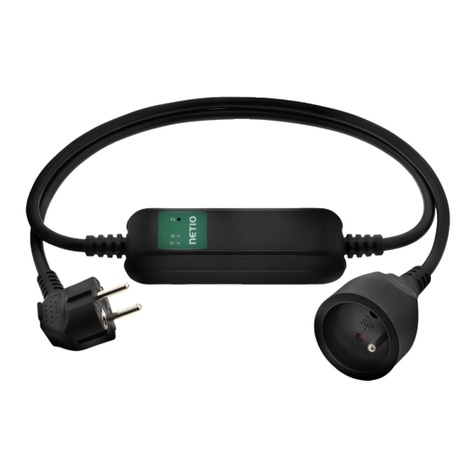
Netio PowerCable Modbus 101 Series User manual

2
Table of Contents
Int roduct ion.............................................................................................................4
1Saf et y not ices ....................................................................................................4
2General charact eristics.........................................................................................4
3PowerCable xxx ..................................................................................................6
4Specifications.....................................................................................................8
4.1 Specificat ions of dif ferent socket t ypes .......................................................9
4.2 Feat ures ........................................................................................... 11
4.3 Drawings........................................................................................... 13
4.4 Device descript ion ............................................................................... 14
4.5 LED and but t on f unct ions....................................................................... 15
4.6 Minimum syst em requirement s (f or conf igurat ion) ........................................ 15
4.7 Package cont ent s ................................................................................ 16
5Conf igurat ion and cont rol .................................................................................... 17
5.1 Connect ing PowerCable t o a local WiFi (AP Mode) ........................................ 17
5.2 NFC inst allat ion in 60 seconds................................................................. 20
5.2.1 NETIO Mobile2 f or Android ......................................................... 20
5.3 Det ect i ng and conf iguri ng t he IP address.................................................... 20
5.4 Login t o device web ............................................................................. 22
5.5 Rest oring f act ory def ault s...................................................................... 23
5.6 Cont rolling t he out put manually .............................................................. 24
6Web int erface .................................................................................................. 25
6.1 Out put s ............................................................................................ 25
6.1.1 Out put s - Energy measurement s.................................................. 26
6.1.2 Out put s - General ................................................................... 27
6.2 M2M API Prot ocol Act ions....................................................................... 29
6.3 Cloud ............................................................................................... 30
6.4 Users ............................................................................................... 33
6.5 Set t ings ............................................................................................ 35
6.5.1 Wi-Fi ................................................................................... 35
6.5.2 Network Configurat ion ............................................................. 36
6.5.3 Dat e / Time .......................................................................... 38
6.5.4 Firmware .............................................................................. 39
6.5.5 Syst em ................................................................................. 41
6.6 Log.................................................................................................. 43
7PowerCable REST 101x........................................................................................ 44
7.1 Overview........................................................................................... 44
7.2 M2M API Prot ocol – XML (REST M2M API) ..................................................... 45
7.3 M2M API Prot ocol – JSON (REST M2M API) .................................................... 49
7.4 M2M API Prot ocol – URL-API (REST M2M API) ................................................ 53
7.5 M2M API Prot ocol – SNMP ....................................................................... 56
8PowerCable Modbus 101x..................................................................................... 59
8.1 Overview........................................................................................... 59
8.2 M2M API Prot ocol – Modbus/ TCP............................................................... 60
8.3 M2M API Prot ocol – Telnet ...................................................................... 64
8.4 M2M API Prot ocol – SNMP ....................................................................... 68
9PowerCable MQTT 101x....................................................................................... 69
9.1 Overview........................................................................................... 69
9.2 M2M API Prot ocol – MQTT-flex ................................................................. 70
9.3 M2M API Prot ocol – Net io Push ................................................................. 73
9.4 M2M API Prot ocol – SNMP ....................................................................... 74
10 PowerCable OEM DevKit 101x................................................................................ 75
10.1 Overview........................................................................................... 75
10.2 OEM – cust om modif icat ions (cust omizat ions) .............................................. 76
11 DECLARATION OF CONFORMITY (RED CE) .................................................................. 77
12 NETIO product s overview ..................................................................................... 78

3

4
Introduction
Thank you f or purchasing t his product of NETIO product s a.s. Bef ore using your product , please read
t his User Manual (MAN) and t he included Quick Inst allation Guide (QIG) t o avoid problems wit h
incorrect inst al lat ion or use.
Caution:
The product works wit h mains vol t age. Mishandl ing may damage it or resul t in inj ur y or deat h.
1Safety notices
1. The manufact urer is not liable f or any damage caused by incorrect use of t he device or by
operat ing it in an unsuit able environment .
2. The device is not rat ed f or out door use.
3. Do not expose t he device t o st rong vibrat ions.
4. Unaut horized modificat ions may damage t he device or cause a fire.
5. Prot ect t he device f rom liquids and excessive t emperat ures.
6. Make sure t he device does not fall.
7. Only elect rical appliances approved for use in t he elect rical net work may be connect ed t o t he
device.
8. Do not connect mult iple devices in series.
9. The cable plug must be easily accessible.
10. The device is complet ely switched off only when unplugged from t he wall socket .
11. If t he device malfunct ions, disconnect it from t he elect rical power supply and cont act your
vendor.
2General characteristics
One met ered and cont rolled 110/ 230V out put
WiFi int erface: 802.11 b/ g/ n; 2.4GHz (secured / unsecured)
WiFi encrypt ion: WEP, WPA, WPA2
AP mode f or connect i ng t he device t o a local WiFi net work (net work select ed f rom a list )
But t on t o act ivat e AP mode
Out put st at e can be toggled with t he On/ OFF but t on (press 3 t imes)
Built -in web server f or device conf igurat ion and cont rol
Password-prot ect ed login int o device conf igurat ion
Electricit y consumption met ering (6 paramet ers): [V, Hz, A, W, Wh, TPF]
Measurement accuracy <1%

5
ZCS (Zero Current Swit ching)
IOC (Independent Out put Cont rol )
PowerUp st at e - (ON / OFF / LAST)
1.2m cable
Overvolt age prot ect ion
Operat ing t emperat ure range: -20° C t o +65° C
Support ed prot ocols: DNS, NTP, DHCP, HTTP
Support ed M2M prot ocols:
PowerCable Modbus 101x: Modbus/ TCP, Telnet , SNMP
PowerCable MQTT 101x: MQTT, Ht t p(s) Push, SNMP
PowerCable REST 101x: XML API, JSON API, URL API, SNMP

6
3PowerCable xxx
PowerCable Modbus 101x PowerCable REST 101x PowerCable MQTT 101x
Overview of t ypes according t o t he support ed M2M prot ocols
Type / Prot ocol
PowerCable
Modbus 101x
PowerCable
REST 101x
PowerCable
MQTT 101x
Web int erface
Yes
Yes
Yes
Telnet
Yes
-
-
Modbus/ TCP
Yes
-
-
URL API
-
Yes
-
XML API
-
Yes
-
JSON API
-
Yes
-
MQTT-flex
-
-
Yes
Netio Push JSON
-
-
Yes
Netio Push XML
-
-
Yes
SNMP v1
Yes
Yes
Yes
PowerCable
Modbus 101x
PowerCable
REST 101x
PowerCable
MQTT 101x
NETIO Cloud
Yes
Yes
Yes
NETIO Mobile2
Yes
Yes
Yes

7
Overview of models according t o t he elect rical socket t ype
Model
Variant Output socket Input plug Voltage
Max.
current
Max.
load
101F
DE
Type F
E/ F (CEE 7/ 7)
230V ~
16A
3600W
101E
FR
Type E
E/ F (CEE 7/ 7)
230V ~
16A
3600W
101J
CH
Type J
Type J
230V ~
10A
2300W
101S
IEC-320 C13/ C14
IEC-320 C13
IEC-320 C14
110/ 230V ~
10A
2300W
101B
US
Type B
Type B
110V ~
15A
1600W
101G
UK
Type G
Type G
230V ~
13A
3000W

8
4Specifications
Power
101E, 101F: 230V~; 50Hz; 16A
101J: 230V~; 50Hz; 10A
101S: 110/230V~; 60/50Hz; 10A
101G: 230V~; 50Hz; 13A
101B: 110V~; 60Hz; 15A
Swit ched out put s
101E, 101F: 230V~; 50Hz; 16[8]A; max. 3600W
101J: 230V~; 50Hz; 10[8]A; max. 2300W
101S: 110/230V~; 60/50Hz; 10[8]A; max. 2300W
101G: 230V~; 50Hz; 13[8]A; max. 3000W
101B: 110V~; 60Hz; 15[8]A; max. 1600W
Surge prot ect ion Type 3 (CAT III)
Int ernal consumpt ion Max 1W
Out put relay
Micro-disconnection (µ) (resistive load)
1E5 switching cycles, max. 1.5kV pulse voltage
Switch heat and fire resistance class 1
Elect rical load
ZCS (Zero Current Swit ching)
- Resist ance load compat ible
- Capacit ive load compat ible
- Induct ive load compat ible
Int erf aces
PowerCable xxx 101x
1x Wi
-Fi 802.11b/g/n 2.4 GHz (internal antenna)
with
WEP/WPA/WPA2
Environment
IP30, protection rating = class 1
Operating temperature -20 .. 65°C (6A load = max. 63°C,
10A = max. 50°C, 16A = max. 30°C)
Device rated for pollution degree 2.
Designed for continuous operation in altitudes up to 2000m.
No additional cooling required.
Caution
The device is not designed to power appliances with a high inrush
current.
Do not connect several devices in series.
The device is safe only when completely disconnected from the
electrical network. The cable plug serves as the disconnection means
and must be easily accessible.
The electrical socket must be earthed and protected with a circuit
breaker rated at 16A or less.

9
4.1 Specifications of different socket types
NETIO products a.s. supplies the PowerCable xxx 101x in several variants with different
electrical plug/ out let types.
Figure 1 - Power Cabl e xxx 101F
(DE–schuko - Type F)
Figure 2 - Power Cabl e xxx 101E
(FR –Type E)
Figure 3 - Power Cabl e xxx 101J
(CH –Type J)

10
Figure 4 - Power Cabl e xxx 101S
(IEC-320 C13/ C14)
Figure 5 - Power Cabl e xxx 101B
(US –Type B)
Figure 6 - Power Cabl e xxx 101G
(UK –Type G)

11
4.2 Features
ZCS (Zero Current Switching)
ZCS (Zero Current Swit ching) funct ion ensures t hat t he relay cont act is closed
at t he moment of zero volt age and opened at t he moment when zero current
f lows t hrough it .
Closing and opening at t hese exact moment s has a number of advant ages:
The negat ive effect s of inrush current on t he lif et ime of t he relay in t he
NETIO device are significant ly reduced.
Reduced probabilit y of a circuit breaker t ripping in t he circuit branch
where t he appliance wit h a high inrush current is connect ed.
Significant ly improved lifet ime of swit ching supplies in appliances t hat are connect ed t o t he
socket (especial ly in case of frequent swit ching on and of f).
Significant ly reduced elect romagnet ic int erf erence caused by repeat ed swit ching on and of f.
Zero current switching (ZCS) significantly improves t he lifet ime of t he PowerCable and t he
connect ed end devices. This f unct ion is part icularly import ant in case of f requent swit ching.
IOC (Independent Output Control)
Independent Out put Cont rol funct ion of t he PowerCable uses an independent
syst em t hat ensures a st able operat ion of t he out put even if t he main syst em
is being rest art ed, updat ed, or is boot ing.
Thanks t o IOC, t he cont rol led out put can power devices t hat , for t echnical
reasons, must be powered wit hout int errupt ion (such as servers). The out put
cont rol is complet ely independent f rom t he WiFi or LAN communicat ion
subsystem.
PowerUp State
The PowerUp St at e paramet er (somet imes also call ed Cold start ) def ines t he
behavior of t he 110/ 230V power out put during t he f irst milliseconds t o seconds
af t er powering up t he devi ce, bef ore t he LAN/ WiFi communicat ion wit h a
mast er syst em is est ablished.
For some applicat ions, it is import ant t o set t he correct st at e of a power
out put immediat ely af t er power is t urned on (or rest ored). Wit h servers in
part icular it is import ant t o avoid undesired moment ary swit ching.
Possible set t ings f or PowerCable
- On
- Off
- LAST st at e rest ores t he last st at e bef ore t he power was disconnect ed

12
Electrical measurements
PowerCable measures relevant elect rical paramet ers.
Parameter
Range
Units
Resolution
Accuracy
Volt age
90,0 – 250,0
V
0,1
<1%
Frequency
45,0 – 65,0
Hz
0,1
<1%
Current
0,005 – 16,000
A
0,001
<1%
TPF
(True Power Fact or) 0,00 – 1,00 - 0,01 <1%
Out put power
0 – 3600
W
1
<1%
Consumpt ion
0 - 4294967296
Wh
1
<1%
Quick WiFi connection setup (AP mode installation)
NETIO PowerCable creat es a WiFi net work t hat you connect t o wit h your PC
or mobile phone.
It t hen scans f or WiFi net works in t he vicinit y, and let s you choose f rom a
list and t ype t he password.
NETIO PowerCabl e t hen conf irms t he connect ion t o t he net work and
displays t he assigned IP address.
NETIO PowerCable devices can be discovered in t he LAN using the NETIO Discover t ool.
NFC Preconfig
PowerCable can be pre-configured using NFC even wit hout being swit ched on.
This require a mobile phone wit h Android syst em, NFC funct ion and mobi le
applicat ion „NETIO Mobile 2“ .
The set t ings configured over NFC will be applied when t he device is powered on.
In t his way, it is possible t o configure or show:
Set SSID and password f or connect ing t o WiFi
Show assigned IP address in DHCP mode
For authent icat ion, t he exist ing password to the web administ rat ion “ admin” account is used
(default “ admin” / “ admin” ).

13
4.3 Drawings
Figure 7 – PoweCabl e xxx 101x side view
Figure 8 – PoweCabl e xxx 101x t op view

14
4.4 Device description
1. Status LED (yellow)
2. Output LED (green)
3. Button – to press, a thin object is needed (may be conductive)
4. Type plate – indicates the device model, electrical rating, maximum switching
power and serial number (fig. 11)
5. Warning: Do not open the device – risk of electric shock!
Rear view
Figure 10 – PoweCable xxx 101x bot t om view
Figure 11 – PoweCable xxx 101x t ype pl at e
SN on the type plate
----------xx
24A42C381234
WiFi network:
PowerCable-AP-xx
PowerCable-AP-34
Front view
Figure 9 –
PoweCabl e xxx 101x
t op vi ew

15
4.5 LED and button functions
Button functions
Controlling
the output
Press 3x within 1 to 5 seconds to switch the output.
AP mode
activation
Press and hold for 10 seconds in the standard operating mode.
Hold until the yellow LED (1) starts flashing rapidly.
The AP mode is activated, making it possible to connect to the device and change the
WiFi network to which it should connect.
Restoring
factory
defaults
Turn the device off, press and hold the button and turn the device on. Hold the button
pressed for at least 10 seconds. The device is reset to factory defaults and the AP mode
is activated (green LED flashes rapidly for 1 second, then yellow LED starts flashing
rapidly).
LED indicators
Status
LED (1)
Yellow
Off
No WiFi connection
On
WiFi connected
Rapidly flashing
& red is off AP mode
Slowly flashing
& red is off
Restoring WiFi connection/
Waiting for DHCP
3 fast flashes every second
& red is off
Locate function – for one minute after enabling in
the web administration
Red
Flash
Activity (command received over M2M)
Output
LED (2) Green
Off
Output relay open
On
Output relay closed
Quick flashing for 1sec
“Load to defaults & AP mode” activated
All
LEDs
Yellow,
red, green Shortly on
During system boot (e.g. after powering up or
rebooting the device)
4.6 Minimum system requirements (for configuration)
A device with an Internet browser (Firefox, Chrome, Safari, Microsoft Internet Explorer, Opera, Mozilla
etc.) that has JavaScript and cookies enabled.

16
4.7 Package contents
- NETIO PowerCable product
- Quick Inst allat ion Guide (QIG)
Figure 11a – PoweCabl e xxx 101x package

17
5Configuration and control
5.1 Connecting PowerCable to a local WiFi (AP Mode)
Plug the NETIO PowerCable int o t he elect rical net work. When t he device is powered up for t he
f irst t ime, it ent ers t he “ AP mode” t hat enables basic conf igurat ion – select ion of a WiFi
net work t o which t he device will connect (yellow LED f lashes rapidly).
On a comput er, t ablet or smart phone, display available WiFi net works and connect t o t he
unsecured “ PowerCable-AP-xx” network (Figure 12).
Device conf igurat ion page should open aut omat ically. If not , open a web browser and ent er
htt p:/ / 10.0. 42. 1 You will see NETIO PowerCable WiFi conf igurat ion page. (Figure 13).
Figure 12 – Connect i ng t o Power Cabl e AP Figure 13 – Web Int er f ace in AP mode

18
Select your net work in t he list of det ect ed net works and click “ Next ” (Figure 14).
Ent er t he password for the select ed WiFi net work. You may also change t he device name. If
your net work does not use DHCP, unselect t his opt ion and manually ent er t he IP address and
ot her net work paramet ers (Figure 16; f or expert s onl y). Click “ Next ” t o confirm (Figure 15).
Figure 14 –Net work sel ect ion in AP mode Figure 15 – Connect ing t o Wi-Fi i n AP mode
If you do NOT use a DHCP server in your net work, set t he
f ollowing paramet ers:
AP Password – password f or t he net work t o which t he
PowerCable will be connect ed
Client IP – IP address in your net work address range
Client mask – net work mask f or your net work
Gat eway – gat eway for your net work
DNS – DNS server for your net work or a public DNS, e. g.
8.8.8.8
Device name – specify a name under which t he
PowerCable will be visible in t he local net work
For more inf ormat ion, see chapt er 5.6 Net work Conf igurat ion
Figure 16 – Conf igur ing t he net work IP par amet er s

19
A page wit h t he connect ion result is displayed. If it shows “ WiFi st at us: Connect ed“ , check t he
net work paramet ers and t hen click “ Save&Connect ” t o save t he configurat ion (Figure 17). The
device t hen exit s t he AP mode, connect s t o t he select ed WiFi net work, and displays a net work
configurat ion summary page (Figure 18). WiFi connect ion is indicat ed wit h t he yellow LED.
Figure 17 – Conf i gur ed Wi -f i paramet er s Figure 18 – Net wor k connect ion i nf o

20
5.2 NFC installation in 60 seconds
NFC (Near Field Communi cat ion) is a t echnology support ed by some mobile phones (and t ablet s).
Using a mobile phone wit h NFC support and t he NETIO Mobile 2 app, even a device that is powered
off can be configured. The device will apply t he new configurat ion as soon as it is powered on.
For example:
NFC can be used t o conf igure t he WiFi connect ion paramet ers (net work SSID + password) in t he
PowerCable MQTT 101x. When t he PowerCable is powered on, it aut omat ical ly connect s t o t he
specif ied WiFi net work.
NFC and t he mobile app can be used t o find out t he IP address assigned t o t he inst alled WiFi
device.
For aut hent icat ion NFC config, t he exist ing password t o t he web administ rat ion “ admin” account is
used (default “ admin” / “ admin” ).
5.2.1 NETIO Mobile2 for Android
NETIO Mobile2 applicat ion is f or cont rol NETIO devices produced
aft er 2016.
Feat ures:
Inst all NFC enabl ed NETIO devices
Swit ch On / Off each power socket on local net work.
Show power consumpt ion on each power out put (if
support ed).
Searching NETIO devices in local net work
ht t ps:/ / play.google.com/ st ore/ apps/ details?id=cz.net io.net io
5.3 Detecting and configuring the IP address
If you have f ollowed t he inst ruct ions in t he previous chapt er, you know t he PowerCable’ s IP
address, whet her it was assigned by a DHCP server or configured manually. If you forgot t he IP
address, or if you have received a pre-configured device, you will need t o find out it s IP address.
Use Windows based NETIO Discover ut ilit y, available for download at ht t p: / / www.net io-
product s.com/ en/ software/ net io-discover.
Depending on your operat ing syst em, choose t he .exe file (Windows) or the .j ar f ile (Linux or Mac).
To run t he .j ar file, JAVA RE is needed. It is available at : www.j ava.com
This manual suits for next models
2
Table of contents
Other Netio Power Distribution Unit manuals

