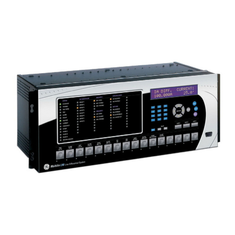
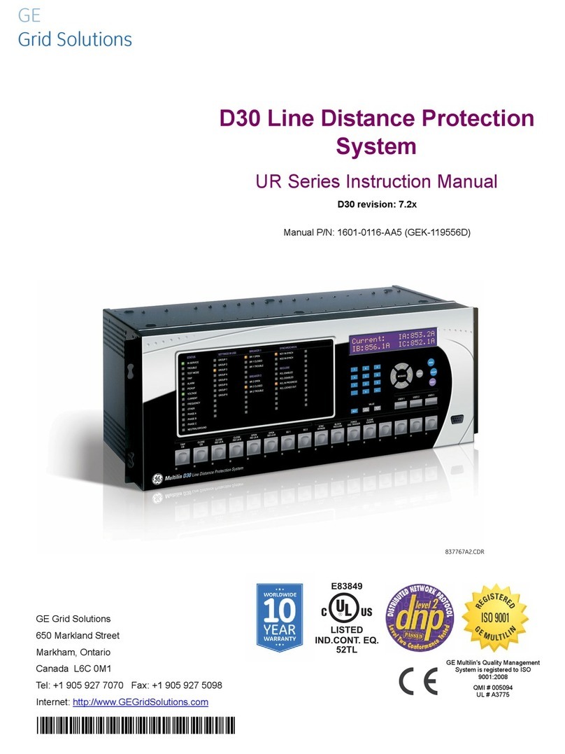
GE ALPS User manual

ALPS
Advanced Line Protection™ System
Instruction Manual
Firmware Revision: V0004.04AA34 (Rev. A models)
Firmware Revision: V0005.02AA05 (Rev. B models)
Manual P/N: GEK-105555F
Copyright © 2002 GE Power Management
GE Power Management
215 Anderson Avenue, Markham, Ontario
Canada L6E 1B3
Tel: (905) 294-6222 Fax: (905) 294-8512
Internet: http://www.GEindustrial.com/pm
Note: All relays must be powered up at least once per year to avoid
deterioration of electrolytic capacitors and subsequent relay failure.
Manufactured under an
ISO9002 Registered system.
g
GE Power Management


These instructions do not purport to cover all details or variations in equipment nor provide for every possible contingency
to be met in connection with installation, operation, or maintenance. Should further information be desired or should partic-
ular problems arise which are not covered sufficiently for the purchaser’s purpose, the matter should be referred to the
General Electric Company.
To the extent required the products described herein meet applicable ANSI, IEEE, and NEMA standards; but no such
assurance is given with respect to local codes and ordinances because they vary greatly.


GE Power Management ALPS Advanced Line Protection System i
TABLE OF CONTENTS
1. PRODUCT DESCRIPTION 1.1 GETTING STARTED
1.1.1 INSPECTION ..................................................................................................... 1-1
1.1.2 PASSWORDS, FACTORY SET......................................................................... 1-1
1.1.3 REMOTE COMMUNICATIONS VIA LOCAL PC................................................ 1-2
1.1.4 ALPS-LINK QUICK REFERENCE ..................................................................... 1-2
1.1.5 ORDERING........................................................................................................ 1-3
1.2 INTRODUCTION
1.2.1 DESCRIPTION................................................................................................... 1-4
1.2.2 APPLICATION ................................................................................................... 1-4
1.2.3 PROTECTION FUNCTIONS..............................................................................1-4
1.2.4 GROUND DISTANCE QUADRILATERAL CHARACTERISTICS......................1-5
1.2.5 LINE PROTECTION SCHEMES........................................................................ 1-8
1.3 CUSTOM PROGRAMMABILITY
1.3.1 INTRODUCTION................................................................................................1-9
1.3.2 PROGRAMMABLE LOGIC ................................................................................ 1-9
1.3.3 CONFIGURABLE INPUTS.................................................................................1-9
1.3.4 CONFIGURABLE OUTPUTS........................................................................... 1-10
1.4 AUXILIARY PROTECTION FUNCTIONS
1.4.1 POTENTIAL TRANSFORMER FUSE FAILURE (PTFF) .................................1-11
1.4.2 LINE PICKUP...................................................................................................1-12
1.4.3 REMOTE-OPEN DETECTOR.......................................................................... 1-13
1.4.4 OUT-OF-STEP BLOCKING ............................................................................. 1-14
1.5 OTHER FEATURES
1.5.1 FLASH MEMORY ............................................................................................ 1-16
1.5.2 LINE OVERLOAD ............................................................................................ 1-16
1.5.3 CURRENT UNBALANCE DETECTION...........................................................1-16
1.5.4 FAULT LOCATION ..........................................................................................1-16
1.5.5 FAULT REPORT.............................................................................................. 1-16
1.5.6 OSCILLOGRAPHY .......................................................................................... 1-16
1.5.7 PLAYBACK ...................................................................................................... 1-17
1.5.8 SEQUENCE OF EVENTS................................................................................ 1-17
1.5.9 EQUIPMENT DUTY......................................................................................... 1-17
1.5.10 SELECTABLE GROUPS OF SETTINGS ........................................................ 1-17
1.5.11 TIME SYNCHRONIZATION.............................................................................1-18
1.5.12 TRIP BUS CHECK........................................................................................... 1-18
1.5.13 TRIP CIRCUIT MONITOR ...............................................................................1-18
1.5.14 ALARMS .......................................................................................................... 1-19
1.5.15 METERING ...................................................................................................... 1-19
1.5.16 BREAKER CONTROL ..................................................................................... 1-19
1.6 COMMUNICATIONS
1.6.1 KEYPAD AND DISPLAY.................................................................................. 1-20
1.6.2 SERIAL COMMUNICATIONS.......................................................................... 1-20
1.6.3 SCADA DIGITAL TO ANALOG (DTA) INTERFACE........................................ 1-20
1.7 SELF-TEST FEATURES
1.7.1 START-UP SELF-TESTS ................................................................................ 1-21
1.7.2 RUN-TIME SELF-TESTS.................................................................................1-21
1.7.3 CONTINUOUS MONITOR...............................................................................1-22
1.8 PROTECTION SCHEMES
1.8.1 INTRODUCTION..............................................................................................1-23
1.8.2 STEP DISTANCE............................................................................................. 1-23
1.8.3 PERMISSIVE UNDERREACH TRANSFER TRIP (PUTT) ..............................1-25
1.8.4 PERMISSIVE OVERREACH TRANSFER TRIP (POTT1)............................... 1-27
1.8.5 POTT WITH BLOCKING FUNCTIONS (POTT2).............................................1-27
1.8.6 BLOCKING SCHEME ...................................................................................... 1-30
1.8.7 HYBRID SCHEME ........................................................................................... 1-33
1.8.8 SINGLE PHASE TRIPPING............................................................................. 1-35
1.9 PHASE IDENITIFIED CHANNEL SCHEMES
1.9.1 DESCRIPTION................................................................................................. 1-38
1.9.2 INTER-CIRCUIT FAULTS................................................................................ 1-38
1.9.3 TWO CHANNEL PHASE IDENTIFIED CHANNEL LOGIC.............................. 1-38
1.9.4 FOUR CHANNEL PHASE IDENTIFIED CHANNEL LOGIC ............................ 1-40

ii ALPS Advanced Line Protection System GE Power Management
TABLE OF CONTENTS
1.10 OUT-OF-STEP TRIPPING (OPTIONAL)
1.10.1 DESCRIPTION .................................................................................................1-41
1.10.2 OST CHARACTERISTIC SHAPE.....................................................................1-41
1.10.3 OUT-OF-STEP DETECTION............................................................................1-42
1.10.4 TWO-CHARACTERISTIC OPERATION...........................................................1-43
1.10.5 OUT-OF-STEP OSCILLOGRAPHY CAPTURE................................................1-43
1.11 COMPENSATED POSITIVE SEQUENCE OVERVOLTAGE (OPTIONAL)
1.11.1 DESCRIPTION .................................................................................................1-44
1.11.2 APPLICATION..................................................................................................1-44
1.12 RECLOSER (OPTIONAL)
1.12.1 DESCRIPTION .................................................................................................1-45
1.12.2 RECLOSING MODE.........................................................................................1-45
1.12.3 RECLOSING PROGRAMS...............................................................................1-45
1.12.4 RECLOSER INPUTS........................................................................................1-46
1.12.5 RECLOSER OUTPUTS....................................................................................1-47
1.12.6 \SYNCHRONISM CHECK (OPTIONAL)...........................................................1-48
1.12.7 ALPS RECLOSING PROGRAM SUMMARY....................................................1-48
1.13 ELEMENTARY DIAGRAMS
1.13.1 ELEMENTARY DIAGRAMS .............................................................................1-49
2. CALCULATION OF
SETTINGS 2.1 INTRODUCTION
2.1.1 DESCRIPTION ...................................................................................................2-1
2.2 GENERAL SETTINGS
2.2.1 CONFIGURATION..............................................................................................2-2
2.2.2 COMMUNICATIONS ..........................................................................................2-4
2.2.3 OSCILLOGRAPHY.............................................................................................2-6
2.2.4 EQUIPMENT DUTY............................................................................................2-6
2.2.5 PROGRAMMABLE INPUTS...............................................................................2-8
2.3 PROTECTION SETTINGS
2.3.1 Z1DISTANCE .....................................................................................................2-9
2.3.2 ZONE 2, ZONE 3, AND ZONE 4 DISTANCE FUNCTIONS.............................2-13
2.3.3 Z2DISTANCE ...................................................................................................2-14
2.3.4 Z3DISTANCE ...................................................................................................2-16
2.3.5 Z4DISTANCE ...................................................................................................2-18
2.3.6 CURSUPVISN ..................................................................................................2-22
2.3.7 OVERCURRNT ................................................................................................2-25
2.3.8 VOLTAGE.........................................................................................................2-27
2.3.9 POSITIVE-SEQUENCE VOLTAGE FUNCTIONS............................................2-28
2.3.10 BLK RECLOS ...................................................................................................2-29
2.3.11 LINEPICKUP ....................................................................................................2-30
2.3.12 REMOTEOPEN ................................................................................................2-31
2.3.13 LINEOVRLD .....................................................................................................2-32
2.3.14 SCHEME ..........................................................................................................2-32
2.3.15 SCHMTIMERS..................................................................................................2-33
2.3.16 LINE INFO ........................................................................................................2-36
2.3.17 SCADA DTA .....................................................................................................2-37
2.3.18 OS BLOCKING.................................................................................................2-38
2.3.19 OS TRIPPING...................................................................................................2-39
2.3.20 RECLOSER......................................................................................................2-41
2.3.21 NONCRIT_AL...................................................................................................2-46
2.3.22 OUTPUTS.........................................................................................................2-46
2.4 INVERSE CURVES
2.5 REFERENCE TABLES
2.5.1 INDEX NUMBERS............................................................................................2-51
2.5.2 PROTECTION SETTINGS GUIDE...................................................................2-57
2.5.3 GENERAL SETTINGS GUIDE .........................................................................2-64
2.5.4 PROTECTION SETTINGS DATA SHEETS .....................................................2-66
2.5.5 GENERAL SETTINGS DATA SHEETS............................................................2-73

GE Power Management ALPS Advanced Line Protection System iii
TABLE OF CONTENTS
3. HARDWARE DESCRIPTION 3.1 CASE ASSEMBLY
3.1.1 CONSTRUCTION .............................................................................................. 3-1
3.1.2 ELECTRICAL CONNECTIONS AND WIRING .................................................. 3-3
3.1.3 IDENTIFICATION...............................................................................................3-3
3.1.4 SYSTEM BLOCK DIAGRAM ............................................................................. 3-4
3.2 INSTALLATION
3.2.1 RECEIVING, HANDLING, AND STORAGE....................................................... 3-5
3.2.2 ENVIRONMENT................................................................................................. 3-5
3.2.3 MOUNTING........................................................................................................ 3-5
3.2.4 EXTERNAL CONNECTIONS............................................................................. 3-5
3.2.5 SURGE GROUND CONNECTIONS.................................................................. 3-5
3.3 PRINTED CIRCUIT BOARD MODULES
3.3.1 WARNING..........................................................................................................3-6
3.3.2 BASIC CONSTRUCTION ..................................................................................3-6
3.3.3 MODULE IDENTIFICATION .............................................................................. 3-6
3.3.4 LOCAL USER INTERFACE (LUI)...................................................................... 3-6
3.3.5 INPUT BOARD................................................................................................... 3-6
3.3.6 MAGNETICS MODULE ..................................................................................... 3-8
3.3.7 COMMUNICATIONS INTERFACE .................................................................... 3-9
3.3.8 DIGITAL OUTPUT / POWER SUPPLY BOARD.............................................. 3-10
3.3.9 DSP / ANI / COMM / LUI.................................................................................. 3-11
3.3.10 960 CPU BOARD............................................................................................. 3-12
4. ACCEPTANCE/PERIODIC
TESTS 4.1 OVERVIEW
4.1.1 INTRODUCTION................................................................................................4-1
4.1.2 TEST EQUIPMENT............................................................................................ 4-1
4.1.3 DRAWINGS AND REFERENCES ..................................................................... 4-1
4.1.4 EQUIPMENT GROUNDING ..............................................................................4-2
4.1.5 REQUIRED SETTINGS ..................................................................................... 4-2
4.1.6 GENERAL INSTRUCTIONS..............................................................................4-2
4.1.7 SETTING CHANGES......................................................................................... 4-3
4.1.8 ENTERING TEST MODE................................................................................... 4-4
4.1.9 USING COMMUNICATIONS (OPTIONAL)........................................................4-4
4.2 GENERAL RELAY TESTS
4.2.1 T1 – RELAY STATUS AND DISPLAY TESTING............................................... 4-7
4.2.2 DISPLAY AND KEYPAD TESTS ....................................................................... 4-7
4.2.3 T2 – DIGITAL OUTPUT TEST........................................................................... 4-8
4.2.4 T3 – CONFIGURABLE INPUT AND OUTPUT TEST ........................................ 4-9
4.2.5 T4 – AC SYSTEM INPUT TEST ...................................................................... 4-10
5. FUNCTIONAL TESTS
(FACTORY SETTINGS) 5.1 TEST SUMMARY
5.1.1 DESCRIPTION................................................................................................... 5-1
5.2 MEASURING UNIT TESTS
5.2.1 T1 – FAULT DETECTOR TEST......................................................................... 5-2
5.2.2 T2 – IT TRIP SUPERVISION TEST...................................................................5-2
5.2.3 T3 – IB BLOCKING SUPERVISION TEST ........................................................ 5-3
5.2.4 T4 – GROUND DIRECTIONAL TRIP TEST, IPT + NT...................................... 5-3
5.2.5 T5 – GROUND DIRECTIONAL BLOCK TEST, IPB + NB.................................. 5-3
5.2.6 T6 – PHASE INSTANTANEOUS OVERCURRENT 50 .....................................5-4
5.2.7 T7 – GROUND INSTANTANEOUS OVERCURRENT 50G...............................5-4
5.2.8 T8 – GROUND TIME OVERCURRENT 51G.....................................................5-4
5.2.9 UNDERVOLTAGE TEST ...................................................................................5-5
5.2.10 T9 – T10 – OVERVOLTAGE TEST ................................................................... 5-5
5.3 ZONE REACH AND TIMER TESTS
5.3.1 GENERAL ZONE REACH TESTING CONSIDERATIONS ............................... 5-8
5.3.2 T11 – ZONE 1 GROUND REACH, M1G GROUND FAULTS............................5-8
5.3.3 T12 – ZONE 2 GROUND REACH, MTG GROUND FAULTS............................5-9
5.3.4 T13 – ZONE 3 GROUND REACH, M3G GROUND FAULTS............................5-9
5.3.5 T14 - ZONE 4 GROUND REACH, M4G GROUND FAULTS...........................5-10

iv ALPS Advanced Line Protection System GE Power Management
TABLE OF CONTENTS
5.3.6 T15 – GROUND (ZONE BACKUP) TIMER TESTS..........................................5-11
5.4 PHASE-TO-PHASE ZONE REACH TESTING
5.4.1 T16 – ZONE 1 PHASE REACH, M1 FAULTS..................................................5-13
5.4.2 T17 – ZONE 2 PHASE REACH, M2 FAULTS..................................................5-13
5.4.3 T18 – ZONE 3 PHASE REACH, M3 FAULTS..................................................5-14
5.4.4 T19 – ZONE 4 PHASE REACH, M4 FAULTS..................................................5-15
5.4.5 T20 – PHASE (ZONE BACK-UP) TIMER TESTS ............................................5-16
5.5 MOB TESTING
5.5.1 T21 – OUT-OF-STEP REACH, MOB................................................................5-19
5.5.2 ENDING FUNCTIONAL TESTS .......................................................................5-19
6. FUNCTIONALTESTS(USER
SETTINGS) 6.1 ALPS FUNCTIONAL TESTS
6.1.1 DESCRIPTION ...................................................................................................6-1
6.1.2 DRAWINGS AND REFERENCES......................................................................6-2
6.1.3 GENERAL INSTRUCTIONS...............................................................................6-3
6.1.4 ENTERING TEST MODE ...................................................................................6-3
6.1.5 USING ALPS-LINK (OPTIONAL) .......................................................................6-3
6.2 GENERAL RELAY TESTS
6.2.1 T1 – LUI RELAY STATUS..................................................................................6-4
6.2.2 T2 – LUI DISPLAY TEST....................................................................................6-4
6.2.3 T3 – DIGITAL OUTPUT TEST............................................................................6-4
6.2.4 T4 – AC SYSTEM INPUT TEST.........................................................................6-5
6.3 MEASURING UNIT TESTS
6.3.1 WARNING ..........................................................................................................6-6
6.3.2 T5 – IT TRIP SUPERVISION TEST ...................................................................6-6
6.3.3 T6 – IB BLOCKING SUPERVISION TEST (BLOCKING SCHEMES)................6-6
6.3.4 T7 – GROUND DIRECTIONAL TRIP TEST, IPT + NT.......................................6-6
6.3.5 T8 – GROUND DIRECTIONAL BLOCK TEST, IPB + NB ..................................6-7
6.4 BACKUP PROTECTION TESTS
6.4.1 T9 – PHASE INSTANTANEOUS OVERCURRENT 50......................................6-8
6.4.2 T10 – GROUND INSTANTANEOUS OVERCURRENT 50G..............................6-8
6.4.3 T11 – GROUND TIME OVERCURRENT 51G....................................................6-9
6.5 ZONE REACH TESTS
6.5.1 GENERAL CONSIDERATIONS .......................................................................6-10
6.5.2 ZONE 1–4 PHASE-TO-GROUND CALCULATIONS........................................6-10
6.5.3 T12 – ZONE 1 GROUND REACH TEST, M1G GROUND FAULTS ................6-12
6.5.4 T13 – ZONE 2 GROUND REACH, MTG GROUND FAULTS ..........................6-13
6.5.5 T14 – ZONE 3 GROUND REACH, M3G GROUND FAULTS...........................6-13
6.5.6 T15 – ZONE 4 GROUND REACH, M4G GROUND FAULTS...........................6-14
6.5.7 ZONE 1 TO 4 PHASE-PHASE REACH CALCULATIONS...............................6-14
6.5.8 T16 – ZONE 1 PHASE REACH, M1 FAULTS..................................................6-16
6.5.9 T17 – ZONE 2 PHASE REACH, MT FAULTS..................................................6-16
6.5.10 T18 – ZONE 3 PHASE REACH, M3 FAULTS..................................................6-17
6.5.11 T19 – ZONE 4 PHASE REACH, M4 FAULTS..................................................6-17
6.5.12 ENDING FUNCTIONAL TESTS (USER SETTINGS).......................................6-17
7. SPECIFICATIONS 7.1 ALPS SPECIFICATIONS
7.1.1 DESCRIPTION ...................................................................................................7-1
8. LOCAL USER INTERFACE 8.1 INTRODUCTION
8.1.1 DESCRIPTION ...................................................................................................8-1
8.1.2 DISPLAY AND KEYPAD ....................................................................................8-1
8.1.3 CONTROL KEYS................................................................................................8-2
8.1.4 MESSAGES........................................................................................................8-3
8.1.5 SETTINGS..........................................................................................................8-4
8.1.6 EDIT PROTECTION SETTINGS........................................................................8-4
8.1.7 [END] KEY..........................................................................................................8-6

GE Power Management ALPS Advanced Line Protection System v
TABLE OF CONTENTS
8.1.8 EDIT GENERAL SETTINGS.............................................................................. 8-7
8.1.9 SELECT ACTIVE SETT GRP ............................................................................ 8-7
8.1.10 MODIFY DATE/TIME......................................................................................... 8-7
8.1.11 ACTIONS ........................................................................................................... 8-8
8.1.12 DISABLE OUTPUTS.......................................................................................... 8-8
8.1.13 ENABLE OUTPUTS........................................................................................... 8-9
8.1.14 TRIP BREAKER................................................................................................. 8-9
8.1.15 CLOSE BREAKER............................................................................................. 8-9
8.1.16 RELAY TEST ................................................................................................... 8-10
8.1.17 CHANNEL TEST.............................................................................................. 8-11
8.1.18 KEYPAD/DISPLAY INTERFACE TEST........................................................... 8-12
8.1.19 DIGITAL OUTPUT TEST ................................................................................. 8-12
8.1.20 PLAYBACK ...................................................................................................... 8-13
8.1.21 CHANGE PASSWORD.................................................................................... 8-14
8.1.22 ENABLE/DISABLE PASSWORDS .................................................................. 8-15
8.1.23 RESET DATA................................................................................................... 8-15
8.1.24 RESET RECLOSER ........................................................................................ 8-15
8.1.25 ADJUST CONTRAST ...................................................................................... 8-15
8.2 INFORMATION
8.2.1 DESCRIPTION................................................................................................. 8-16
8.2.2 REQUEST STATUS INFORMATION .............................................................. 8-16
8.2.3 REQUEST FAULT INFORMATION ................................................................. 8-17
8.2.4 REQUEST PRESENT VALUES....................................................................... 8-18
8.2.5 CONTACT CONVERTER STATUS.................................................................8-18
8.2.6 DIGITAL OUTPUT STATUS ............................................................................ 8-18
8.2.7 EVENT INFORMATION................................................................................... 8-19
8.2.8 COMMUNICATION PASSWORDS.................................................................. 8-21
8.2.9 REQUEST STATION/LINE ID.......................................................................... 8-21
8.2.10 REQUEST ALPS MODEL/VERSION............................................................... 8-21
8.2.11 OSCILLOGRAPHY SNAPSHOT...................................................................... 8-22
8.3 ASCII INTERFACE
8.3.1 DESCRIPTION................................................................................................. 8-23
8.3.2 RECOMMENDED REMOTE COMMUNICATIONS PACKAGE.......................8-23
8.4 REMOTE COMMUNICATION INTERFACE
8.4.1 HARDWARE SWITCHES ................................................................................ 8-24
8.4.2 MODEM CONNECTIONS AND SETTINGS .................................................... 8-24
8.4.3 PC MODEM ..................................................................................................... 8-25
8.4.4 ALPS MODEM ................................................................................................. 8-25
8.4.5 NULL-MODEM CONNECTIONS ..................................................................... 8-27
9. SERVICING 9.1 SPARES
9.1.1 DESCRIPTION................................................................................................... 9-1
9.1.2 SERVICING WITH THE RELAY SELF-TEST.................................................... 9-1
9.2 TROUBLESHOOTING
9.2.1 DESCRIPTION................................................................................................... 9-3
9.2.2 THE INFORMATION STATUS COMMAND....................................................... 9-3
9.2.3 SERVICING A CRITICAL FAILURE .................................................................. 9-3
9.2.4 LOCATING THE DEFECTIVE BOARD.............................................................. 9-4
9.2.5 SERVICING A NON-CRITICAL FAILURE ......................................................... 9-4
9.2.6 LOCATING THE DEFECTIVE BOARD.............................................................. 9-4
9.2.7 SERVICE SYSTEM STATUS FAILURES.......................................................... 9-5
10. ALPS TEST PROGRAM 10.1 INTRODUCTION
10.1.1 DESCRIPTION................................................................................................. 10-1
10.1.2 STARTING PROGRAM AFTER THE FIRST TIME ......................................... 10-1
10.2 TEST CALCULATIONS
10.2.1 DESCRIPTION................................................................................................. 10-2
10.2.2 ENTERING INPUT QUANTITIES .................................................................... 10-2
10.2.3 ENTERING A VALUE ...................................................................................... 10-3
10.2.4 SELECTING A VALUE..................................................................................... 10-3

vi ALPS Advanced Line Protection System GE Power Management
TABLE OF CONTENTS
10.2.5 M1 PHASE UNITS – ZONE 1...........................................................................10-3
10.2.6 MT PHASE UNITS – ZONE 2...........................................................................10-4
10.2.7 M3 PHASE UNITS – ZONE 3...........................................................................10-4
10.2.8 M4 PHASE UNITS – ZONE 4...........................................................................10-5
10.2.9 MOB PHASE UNIT...........................................................................................10-5
10.2.10 MIG GROUND UNITS – ZONE 1 .....................................................................10-6
10.2.11 MTG GROUND UNITS – ZONE 2....................................................................10-6
10.2.12 M3G GROUND UNITS – ZONE 3 ....................................................................10-7
10.2.13 M4G GROUND UNITS – ZONE 4 ....................................................................10-7
10.3 FILE MENU
10.3.1 NEW TEST FILE...............................................................................................10-8
10.3.2 OPEN TEST FILE.............................................................................................10-8
10.3.3 OPEN SETTING FILE ......................................................................................10-8
10.3.4 CLOSE TEST FILE...........................................................................................10-9
10.3.5 SAVE INPUT QUANTITIES..............................................................................10-9
10.3.6 SAVE INPUT QUANTITIES AS......................................................................10-10
10.3.7 SAVE OUTPUT AS.........................................................................................10-10
10.3.8 PRINT.............................................................................................................10-10
10.3.9 PRINT SETUP................................................................................................10-10
10.3.10 LAST 4 OPENED SETTINGS FILES..............................................................10-10
10.3.11 EXIT................................................................................................................10-10
10.4 EDIT MENU
10.4.1 COPY..............................................................................................................10-11
10.4.2 COPY TEXT ONLY.........................................................................................10-11
10.4.3 COPY MHO CIRCLE ONLY ...........................................................................10-11
10.5 VIEW MENU
10.5.1 DESCRIPTION ...............................................................................................10-12
10.5.2 TOOLBAR.......................................................................................................10-12
10.5.3 STATUS BAR .................................................................................................10-12
10.6 TOOLS MENU
10.6.1 DESCRIPTION ...............................................................................................10-13
10.7 WINDOW MENU
10.7.1 DESCRIPTION ...............................................................................................10-15
10.7.2 CASCADE ......................................................................................................10-15
10.7.3 TILE ................................................................................................................10-15
10.7.4 ARRANGE ICONS..........................................................................................10-15
10.7.5 VIEWING MULTIPLE TESTS.........................................................................10-15
10.8 HELP MENU
10.8.1 CONTENTS....................................................................................................10-16
10.8.2 ABOUT ALPS_TST ........................................................................................10-16
11. ALPS-LINK USER GUIDE 11.1 INSTALLATION
11.1.1 OVERVIEW ......................................................................................................11-1
11.1.2 USING ON-LINE HELP ....................................................................................11-1
11.1.3 SUPPORTED ARCHITECTURE ......................................................................11-1
11.1.4 HARDWARE INSTALLATION ..........................................................................11-1
11.1.5 SOFTWARE INSTALLATION...........................................................................11-3
11.2 USING ALPS-LINK
11.2.1 STARTUP.........................................................................................................11-5
11.2.2 MENU BAR.......................................................................................................11-5
11.2.3 TOOLBAR.........................................................................................................11-5
11.2.4 STATUS BAR ...................................................................................................11-5
11.3 SETTING UP YOUR HOST MACHINE
11.3.1 DESCRIPTION .................................................................................................11-6
11.3.2 COM PORT SETUP .........................................................................................11-6
11.3.3 MODEM SETUP...............................................................................................11-6
11.3.4 PRINTER SETUP.............................................................................................11-7
11.3.5 DEVICE SETUP ...............................................................................................11-7
11.3.6 ADDING A DEVICE..........................................................................................11-7

GE Power Management ALPS Advanced Line Protection System vii
TABLE OF CONTENTS
11.4 CONNECTING TO AND LOGGING OUT OF A DEVICE
11.4.1 DESCRIPTION................................................................................................. 11-9
11.4.2 CONNECT TO A DEVICE................................................................................ 11-9
11.4.3 LOGOUT FROM A DEVICE............................................................................. 11-9
11.5 SETTINGS AND ACTIONS
11.5.1 SETTINGS ..................................................................................................... 11-10
11.5.2 ACTIONS ....................................................................................................... 11-12
11.6 INFORMATION
11.6.1 DESCRIPTION...............................................................................................11-14
11.6.2 OPEN REPORT............................................................................................. 11-14
11.6.3 NEW REPORT............................................................................................... 11-14
11.6.4 FAULT REPORT............................................................................................11-15
11.6.5 OSCILLOGRAPHY REPORT ........................................................................11-15
11.6.6 BREAKER HEALTH REPORT....................................................................... 11-15
11.6.7 DEMAND REPORT........................................................................................11-15
11.6.8 DIAGNOSTICS REPORT ..............................................................................11-15
11.6.9 EVENT REPORT ...........................................................................................11-15
11.6.10 PRESENT VALUES REPORT.......................................................................11-15
11.6.11 STATUS REPORT.........................................................................................11-15
11.6.12 CONTACT STATUS REPORT.......................................................................11-16
11.6.13 LUI PASSWORD REPORT............................................................................11-16
11.6.14 OPEN REPORT............................................................................................. 11-16
11.6.15 SAVE REPORT.............................................................................................. 11-16
11.6.16 PRINT REPORT ............................................................................................11-16
11.7 LOGGING
11.7.1 SESSION LOG...............................................................................................11-17
11.7.2 TURN OFF.....................................................................................................11-17
11.7.3 CURRENT SESSION LOG............................................................................11-17
11.7.4 OPEN SESSION LOG ...................................................................................11-17
11.7.5 ARCHIVAL ..................................................................................................... 11-17
11.7.6 ARCHIVE ....................................................................................................... 11-17
11.7.7 RETREIVE ..................................................................................................... 11-18
12. ASCII COMMUNICATIONS 12.1 INTRODUCTION
12.1.1 DESCRIPTION................................................................................................. 12-1
12.1.2 ASCII INTERFACE ..........................................................................................12-1
13. XPRESSION BUILDER 13.1 INTRODUCTION
13.1.1 OVERVIEW...................................................................................................... 13-1
13.1.2 INSTALLATION................................................................................................ 13-1
13.1.3 DESIGN CONSIDERATIONS.......................................................................... 13-1
13.1.4 BOOLEAN OPERATORS, LATCHES, TIMERS, & COUNTERS .................... 13-2
13.2 XPRESSION BUILDER FLAGS
13.2.1 CONTACT CONVERTER INPUTS.................................................................. 13-4
13.2.2 INPUT/OUTPUT FLAGS.................................................................................. 13-4
13.3 CREATING XPRESSION BUILDER LOGIC
13.3.1 DESCRIPTION................................................................................................. 13-9
13.3.2 COMPILING AND DOWNLOADING XPRESSION BUILDER LOGIC...........13-11
13.3.3 BREAKER FAILURE EXAMPLE....................................................................13-11
14. ALPS-SET PC SOFTWARE 14.1 INTRODUCTION
14.1.1 INSTALLATION................................................................................................ 14-1
14.1.2 STARTING THE PROGRAM ........................................................................... 14-1
14.1.3 PRINT SETTINGS REPORT ........................................................................... 14-3
14.1.4 EDIT MENU – COPY SETTINGS REPORT .................................................... 14-3
14.1.5 TOOLS MENU ................................................................................................. 14-3
14.1.6 HELP MENU .................................................................................................... 14-4

viii ALPS Advanced Line Protection System GE Power Management
TABLEOFCONTENTS
A. FREQUENTLY ASKED
QUESTIONS A.1 FREQUENTLY ASKED QUESTIONS
B. MODBUS B.1 MODBUS INTRODUCTION
B.1.1 DESCRIPTION..................................................................................................B-1
B.1.2 COMMUNICATIONS SETTINGS......................................................................B-1
B.1.3 SUPPORTED MODBUS FUNCTIONS..............................................................B-1
B.1.4 EXCEPTION OR ERROR REPLIES.................................................................B-2
B.1.5 DATA FORMATS...............................................................................................B-2
B.2 REGISTER MAPS
B.2.1 SUMMARY........................................................................................................B-3
B.2.2 MODBUS MEMORYMAP.................................................................................B-5
B.2.3 MEMORY MAP DATA FORMATS...................................................................B-15
C. DNP C.1 OVERVIEW
C.1.1 DESCRIPTION..................................................................................................C-1
C.1.2 MODIFYING SETTINGSUSING DNP...............................................................C-1
C.2 DEVICE PROFILE
C.2.1 DNP V3.00 DEVICE PROFILE DOCUMENT....................................................C-2
C.2.2 IMPLEMENTATION TABLE..............................................................................C-4
C.2.3 IMPLEMENTATION TABLE NOTES.................................................................C-5
C.2.4 DEFAULT VARIATIONS....................................................................................C-5
C.3POINT LISTS
C.3.1 DESCRIPTION..................................................................................................C-6
C.3.2 BINARY INPUT, BINARY INPUT CHANGE......................................................C-6
C.3.3 BINARY OUTPUT, CONTROL RELAY OUTPUT BLOCK..............................C-11
C.3.4 BINARY COUNTER, FROZEN COUNTER.....................................................C-12
C.3.5 ANALOG INPUT, ANALOG INPUT CHANGE.................................................C-13
C.3.6 ANALOG OUTPUT, ANALOG OUTPUT BLOCK............................................C-19
C.3.7 DATA FORMATS – ANALOG INPUT AND OUTPUT POINTS.......................C-26
D. KEYPAD MENUS D.1 KEYPAD MENUS
D.1.1 SETKEYPAD MENU.........................................................................................D-1
D.1.2 ACT KEYPAD MENU........................................................................................D-2
D.1.3 INF KEYPAD MENU..........................................................................................D-3
E. FIGURES AND TABLES E.1 FIGURES AND TABLES
E.1.1 LIST OF FIGURES............................................................................................E-1
E.1.2 LIST OF TABLES..............................................................................................E-3
F. WARRANTY F.1 WARRANTY INFORMATION
F.1.1 GE POWER MANAGEMENT WARRANTY.......................................................F-1
INDEX INDEX

GE Power Management ALPS Advanced Line Protection System 1-1
1 PRODUCT DESCRIPTION 1.1 GETTING STARTED
1
1 PRODUCT DESCRIPTION 1.1 GETTING STARTED 1.1.1 INSPECTION
Before attempting to install or use this relay, it is imperative that all WARNINGS and CAUTIONS in this man-
ual are reviewed to help prevent personal injury, equipment damage, and/or downtime.
Unpack the relay, the mounting brackets, and the hardware for attaching the mounting brackets to the sides of the relay.
Examine the relay for any damage sustained in transit, and if damage is evident, notify the shipping company and the near-
est GE Power Management sales office immediately.
Prior to applying power, ensure that the model number of the relay listed on the front panel corresponds to the model
ordered. Make sure that the DC supply power matches the rated voltage listed on the front panel. Refer to the elementary
diagrams on pages 1–49 to 1–52 for the locations of the DC power inputs
Instructions on using the keypad to change settings and put the relay into test mode can be found in Section 4.1.7: SET-
TING CHANGES on page 4–3. Complete instructions on operating the keypad are found in Chapter 8: LOCAL USER
INTERFACE.
GE Power Management contact information:
GE Power Management
215 Anderson Avenue
Markham, Ontario
Canada L6E 1B3
Telephone: Toll Free North America: (800) 547-8629
Europe +34 94 485 88 54
Other Areas (905) 294-6222
Emergency (416) 414-4941
Fax: (905) 201-2098
Email: info.pm@indsys.ge.com
Home Page: www.GEindustrial.com/pm
1.1.2 PASSWORDS, FACTORY SET
The ALPS requires passwords to change settings or perform actions. No password is required to obtain information from
the relay, including viewing the existing settings. The relay is shipped from the factory with the following MMI passwords:
SETTINGS: 123.
ACTIONS: 456.
MASTER: 789.
The decimal point following the digits is part of the password. Factory passwords MUST be changed
before the user can modify settings or initiate Actions.
In order to change the default password, follow these steps:
1. Press the ACTIONS key [ACT].
2. Press the ENTER key [ENT].
3. Scroll to the CHANGE PASSWORD option.
4. Select the Password Privilege level to be changed.
5. Press [ENT].
6. Enter the factory password (for example: 789. for Master Password).
7. Enter your password.
8. Re-enter your password.
9. Press [END], press [ENT], and then press [CLR].
The keypad passwords stored in the relay may be viewed, in encoded format, via remote communications.
NOTE
NOTE

1-2 ALPS Advanced Line Protection System GE Power Management
1.1 GETTING STARTED 1 PRODUCT DESCRIPTION
11.1.3 REMOTE COMMUNICATIONS VIA LOCAL PC
To communicate with the relay through a PC, connect the relay to a serial port of an IBM-compatible computer with a
null-modem cable. Connection can be made either to the 25 pin D-connector on the back of the relay (PL2A), or the 9 pin
D-connector on the front (PL1). Cable diagrams are shown in the following:
• Figure 8–2: MODEM CABLE on page 8–23
• Figure 8–3: 25-PIN NULL MODEM CABLE on page 8–23
• Figure 8–4: 25-PIN NULL MODEM CABLE on page 8–27
• Figure 8–5: NULL MODEM CABLE FOR PORT PL1 on page 8–27
The communications software required to access the relay, ALPS-Link, is included on the enclosed Products CD. Follow
instructions in Section 11.1.5 SOFTWARE INSTALLATION on page 11–3 to load ALPS-Link onto the PC.
1.1.4 ALPS-LINK QUICK REFERENCE
The ALPS relay requires the use of passwords to obtain information from the relay, to change Settings, or to perform
Actions. The relay is shipped from the factory with the following communications passwords:
VIEW: VIEW!
SETTINGS: SETTING!
ACTIONS: CONTROL!
MASTER: MASTER!
The exclamation point following the letters is part of the factory password. The factory passwords MUST
be changed before the user can modify Settings or initiate Actions. The user can log into the relay at any
password level. After logging into the relay, the password can be changed under the ACTION menu by
selecting CHANGE PASSWORD.
The user must logout from the ALPS before changing another password. The remaining passwords can then be changed
by logging into the ALPS using another default password. The communications passwords may be viewed, in an encoded
format, via the [INF] (information) key.
To log into the relay, follow the instructions in Section 4.1.9: USING COMMUNICATIONS (OPTIONAL) on page 4–4. Any
one of the factory passwords can be used to log on to the relay. The relay UNITID (General Setting 101) is factory set to
"0".
NOTE

GE Power Management ALPS Advanced Line Protection System 1-3
1 PRODUCT DESCRIPTION 1.1 GETTING STARTED
1
1.1.5 ORDERING
† These options are applicable to Revision A models only.
EXAMPLE: ALPSDA35U122VE1N = ALPS Digital Line Protection Distance Relay; revision A; three phase tripping logic;
rated at 5 amperes; without series capacitor protection; 110/125 VDC supply; contact tripping outputs; 2 communications
ports; vertical mounting; with extended memory; without OST functions; and no recloser.
Table 1–1: ORDER CODES
ALPS * * * * * * * * * * * * – *
Base Unit ALPS |||||||||||| | Base Unit
Distance Relay D| | | | | | | | | | | | Distance Relay
Revision A|||||||||| | ALPS Revision A
B|||||||||| | ALPS Revision B
Tripping Logic 1| | | | | | | | | | Single Phase Tripping Logic
3| | | | | | | | | | Three Phase Tripping Logic
Current Rating 1|||||||| | 1 Ampere rated current
5|||||||| | 5 Ampere rated current
Series
Capacitors U| | | | | | | | For applications without series capacitors
C| | | | | | | | For Applications with series capacitors
Battery
Voltage 0|||||| | 48V DC battery voltage
1|||||| | 110/125 V DC battery voltage
2|||||| | 220/250 V DC battery voltage
Trip Outputs 1| | | | | | SCR trip outputs & contact channel interface
2| | | | | | Contact trip outputs & contact channel interface
3| | | | | | SCR trip outputs & 5V / 20mA channel interface
4| | | | | | Contact trip outputs & 5V / 20 mA channel interface
Comm Ports 2|||| | Front RS232 port & 1 settable RS232/RS485 rear port (GEmodem/ASCII)†
3|||| | Front RS232 port & 2 settable RS232/RS485 rear ports (GEmodem/ASCII)
Mounting H| | | | Horizontal mounting
V| | | | Vertical mounting
Oscillography S|| | Standard oscillography memory †
E|| | Extended oscillography memory
OST / Positive
Sequence
Overvoltage
0| | No out-of-step tripping or positive sequence overvoltage †
1| | With out-of-step tripping †
2| | With positive sequence overvoltage units †
3| | With positive sequence overvoltage units & out-of-step tripping
Recloser N|No recloser
R|Recloser
S|Recloser with sync check
Protocol AC Modbus RTU communication †

1-4 ALPS Advanced Line Protection System GE Power Management
1.2 INTRODUCTION 1 PRODUCT DESCRIPTION
11.2 INTRODUCTION 1.2.1 DESCRIPTION
The Advanced Line Protection System (ALPS) is a microprocessor-based digital relay system that uses waveform sam-
pling with appropriate algorithms to provide three phase or single phase tripping schemes for transmission line protection,
fault location, and related features. The models covered by this instruction book are intended for either three phase or sin-
gle phase tripping applications. The relay samples the current and voltage inputs from the power system 64 times per
cycle. Protection algorithms process this sampled data in sets of four, sixteen times per cycle. The ALPS uses advanced
Fourier calculation techniques and adaptive measuring functions to achieve high-speed tripping for severe faults.
The ALPS is packaged in a compact 3 Rack Unit high (one RU = 1.75 Inches) 19-inch rack mount case and is available for
either horizontal or vertical mounting. The case outline and mounting dimensions are shown in Figure 3–2: FRONT AND
REAR VIEW on page 3–2.
All models include a full keypad and a liquid crystal display (LCD) for local access to relay data and settings. In addition, up
to three communication ports are provided for both local and remote access with a PC. Each port may be independently set
for ASCII or GEmodem protocols.
1.2.2 APPLICATION
The models covered by this instruction book are designed to be used on transmission lines of any voltage level, with or
without series capacitor compensation, where either single or three-phase tripping is required. Detailed application consid-
erations are described in this chapter and in Chapter 2: CALCULATION OF SETTINGS.
The ALPS can provide high speed detection and clearing of power system faults, and includes logic for step distance and
five standard pilot tripping schemes. The scheme logic is described in Section 1.8: PROTECTION SCHEMES on page 1–
23. The external connections for the ALPS are shown in the elementary diagrams on pages 1–49 to 1–52.
The ALPS is available with either a contact interface to the pilot channel equipment or an electronic (5 V, 20 mA) interface
so that the relay may be applied with a wide variety of channel equipment. Typical channels include: AM and FSK via power
line carrier (PLC), FSK via microwave, and multiplexed fiber optic cable.
1.2.3 PROTECTION FUNCTIONS
The measurement functions are listed in Table 1–2: ALPS MEASUREMENT FUNCTIONS on page 1–5.
The Zone 1 distance functions provide secure high-speed tripping for all fault types over most of the protected line. The
Zone 1 ground distance functions can be selected to be either ground variable-Mho distance functions, or ground-reac-
tance distance functions. The ALPS also offers ground quadrilateral distance functions as Zone 1 ground distance func-
tions. A unique adaptive reach for the supervising Mho characteristic is used when ground-reactance functions are
selected.
Overreaching Zone 2 phase and ground distance functions are used for pilot tripping schemes. Ground-directional overcur-
rent functions can be selected to replace or supplement the overreaching zone (Zone 2) ground-distance functions in any
of the pilot schemes. The ALPS also offers Zone 2 ground quadrilateral characteristics. The Zone 2 phase and ground dis-
tance functions are provided with independent timers for time delayed backup protection.
Overreaching Zone 3 phase and ground distance functions are provided with independent timers for time delayed backup
protection. The ALPS also has the option for quadrilateral ground-distance functions.
The Zone 4 variable-Mho distance functions can be reversed in direction when a reversed or blocking function is required.
When the POTT2, Blocking or Hybrid scheme is selected, Zone 4 is automatically set to the reverse direction, because
these schemes require a reverse-looking blocking function. The Zone 4 phase and ground distance functions are provided
with independent timers for time delayed backup protection. The ALPS with three phase tripping also has the option to use
Zone 4 ground quadrilateral distance functions for time-delayed backup protection.
When both phase and ground distance functions are used for a zone of protection, six individual measuring functions are
available: three for phase distance and three for ground distance. The algorithm that implements the variable-Mho measur-
ing functions is derived from designs that have evolved through several different families of static analog and digital relay
systems which have accumulated decades of dependable and secure in-service experience.
An instantaneous overcurrent tripping function (50G) provides direct tripping for severe phase-to-ground faults. Time-over-
current tripping (51G) provides time-delayed backup tripping for phase-to-ground faults. Either or both of these ground-
overcurrent functions can be controlled by the NT negative-sequence directional trip unit, at the customer’s discretion.

GE Power Management ALPS Advanced Line Protection System 1-5
1 PRODUCT DESCRIPTION 1.2 INTRODUCTION
1
1.2.4 GROUND DISTANCE QUADRILATERAL CHARACTERISTICS
The ALPS relay has been modified to include the option to use either quadrilateral characteristics or variable Mho charac-
teristics for all zones of ground distance protection. The model numbers affected by this modification are: ALPSD-
B
XXXXXXXXX
(where
X
may be any valid character) with firmware version V0005.00AA00 or higher. A new version of
ALPS-Link may be required to access the new settings via remote communications (ALPS-Link must be version 3.5 or
higher). If required, the updated version of ALPS-Link may be downloaded from the GE power Management website at
www.GEindustrial.com/pm.
Many protective relay engineers prefer to use a quadrilateral (polygonal) characteristic for ground distance functions to pro-
vide more fault resistance coverage than the circular mho characteristic. A typical quadrilateral characteristic is shown in
Figure 1–1: GROUND DISTANCE QUADRILATERAL CHARACTERISTIC. The characteristic is comprised of four straight
lines; the trip zone is the inside area bounded by all four characteristics. The upper boundary, the reactance characteristic,
may also be used with a variable mho function. The variable mho provides both directional supervision for reverse faults.
and resistive limits to prevent operation on load.
Table 1–2: ALPS MEASUREMENT FUNCTIONS
ZONE OR TYPE FUNCTIONS
Zone 1 • 3 Variable-Mho phase-distance functions
• 3 Variable-Mho ground-distance functions
• 3 Reactance ground-distance functions with “adaptive reach” Mho supervision or
3 Quadrilateral ground-distance functions (Revision B relays only).
Zone 2 (Pilot Zone) • 3 Variable-Mho phase distance functions
3 Variable Mho ground-distance functions and/or
Ground directional-overcurrent functions consisting of:
IPT: Ground Trip overcurrent
NT: Negative Sequence Directional Trip
IPB: Ground Block overcurrent
NB: Negative Sequence directional block
or
3 Quadrilateral ground-distance functions (Revision B relays only)
Zone 3 • 3 Variable-Mho phase-distance functions
• 3 Variable-Mho ground-distance functions, or
3 Quadrilateral ground-distance functions (Revision B relays only)
Zone 4 • 3 Reversible variable-Mho phase-distance functions
• 3 Reversible variable-Mho ground-distance functions, or
3 Quadrilateral ground-distance functions (Revision B relays only)
Out of Step Blocking (OSB) • 3 Variable-Mho phase-distance functions
Overcurrent Backup • 50: Phase-overcurrent direct trip (directional or nondirectional
• 50G: Ground-overcurrent direct trip (directional or nondirectional)
• 51G: Ground time-overcurrent direct trip (directional or nondirectional)
Overcurrent Supervision • IT: Trip-supervision overcurrent
• IB: Block-supervision overcurrent
Fault Detector • FD
Line-Pickup Overcurrent • I1
Remote-Open Detectors • ROD
Line-Overload Detectors • Level 1 Overcurrent
• Level 2 Overcurrent
Phase Undervoltage • Three fixed pickup phase undervoltage detectors
Phase Over / Undervoltage • Three adjustable over or under voltage detectors with time delay
Positive-Sequence Voltage
Detectors •V1,
• V1 compensated
Out of Step Tripping (OST) • 3 Variable-Mho positive sequence-distance functions

1-6 ALPS Advanced Line Protection System GE Power Management
1.2 INTRODUCTION 1 PRODUCT DESCRIPTION
1
Figure 1–1: GROUND DISTANCE QUADRILATERAL CHARACTERISTIC
In the ALPS relay the four straight lines of the quadrilateral characteristic are developed by a combination of the following
three characteristics:
1. Reactance characteristic (section 1). The tilt of the reactance characteristic is determined by the characteristic timer
setting. The range of the setting is 80° to 155° in 1° steps.
2. Restricted directional characteristic (sections 2 and 4)
3. Right (positive) resistive blinder (section 3)
The following definitions pertain to all of the distance functions:
I
A
= phase A current at relay
I
B
= phase B current at relay
I
C
= phase C current at relay
I
0= zero-sequence current at relay
V
A
= phase A to ground voltage at relay
V
B
= phase B to ground voltage at relay
V
C
= phase C to ground voltage at relay
X
1= positive-sequence component of
X
X
2= negative-sequence component of
X
X
M= memory (pre-fault) value of
X
Z
x
1= Zone
x
positive-sequence reach setting:
ZxR
∠POSSEQANG
Z
x
0= Zone
x
zero-sequence reach setting:
ZxR
∠ZERSEQANG
Note: The magnitudes of
Zx
1and
Zx
0are identical - these quantities differ in phase angle only.
K
01 = Zone 1 zero-sequence compensation factor: Z1K0
K
0= zero-sequence compensation factor
a) REACTANCE CHARACTERSTIC
The reactance characteristic used for the ground quadrilateral is the similar as the existing negative / zero sequence phase
angle comparator reactance characteristic. The function has been modified by the addition of a fourth comparator input
(Pol. #3). The operate and polarizing signals used in this function are:
Operate:
Iφ
′
Z
–
Vφ
Pol.# 1:
I
0
Z
1
Pol.# 2:
I
2
Z
1
Pol.# 3:
I
1
F
Z
1
where:
Iφ
′
Z
is the compensated
IZ
product
Z
1is the positive sequence replica impedance
Vφ
is the phase to ground voltage
I
0is the zero sequence current component
I
2is the negative sequence current component, referenced to the proper phase.
I
1
F
is the fault component of the positive sequence current component, referenced to the proper phase.
The pre-fault load current is removed from this quantity.
R
X
1
3
2
4

GE Power Management ALPS Advanced Line Protection System 1-7
1 PRODUCT DESCRIPTION 1.2 INTRODUCTION
1
All zones of ground reactance characteristics will have a characteristic timer with a pickup range of 90 to 155° in steps of 1.
The characteristic timer setting will be used to “tilt” the reactance characteristic (Tent) to prevent over-reach on non-homo-
geneous systems, as shown below. Note that the “tent” is not the same as tilting the reactance because it also tilts down to
the left of the maximum reach balance point. By adjusting the angle of the phase angle comparator rather than the angle of
“maximum torque”, the transient over reach is not increased.
Figure 1–2: TENT CHARACTERISTIC
For the Zone 1 ground function, the signals are:
Phase A: (
I
A
-
I
0)·
Z
11+
K
01·
I
0·
Z
10–
V
A
I
A
2·
Z
11
I
0·
Z
11
I
A
1
F
·
Z
11
Phase B: (
I
B
-
I
0)·
Z
11+
K
01·
I
0·
Z
10–
V
B
I
B
2·
Z
11
I
0·
Z
11
I
B
1
F
·
Z
11
Phase C: (
I
C
-
I
0)·
Z
11+
K
01·
I
0·
Z
10–
V
C
I
C
2·
Z
11
I
0·
Z
11
I
C
1
F
·
Z
11
b) RESTRICTED DIRECTIONAL CHARACTERISTIC
The restricted directional characteristic for the ground quadrilateral requires a separate directional unit for each phase. No
settings are required for this characteristic. The input signals to the comparator are:
Phase A:
I
A
·
ZD
V
A
Phase B:
I
B
·
ZD
V
B
Phase C:
I
C
·
ZD
V
C
where
ZD
is the angle of “maximum torque” and is equal to 65°.
The characteristic timer angle will be fixed at 115°. That is, the function will operate when the input signals are within ±65°
of each other.
If the faulted phase voltage magnitude is too low (as for a close-in Zone 1 fault), the phase directional function will not oper-
ate. This might also occur for a remote fault when the relay is located near a strong source. Therefore, if the phase voltage
is less than the minimum threshold voltage, the positive-sequence memory voltage from the ground Mho functions is used
in place of the phase voltage to polarize the directional function.
R
X
1
3
2
4
“TENT” CHARACTERISTIC
TENTCHAR.CDR

1-8 ALPS Advanced Line Protection System GE Power Management
1.2 INTRODUCTION 1 PRODUCT DESCRIPTION
1c) RIGHT RESISTIVE BLINDER
The right resistive blinder is a two input phase angle comparator. The input signals for the comparator are:
Operate:
Iφ
′·
RB
1 -
Vφ
Polarize:
Iφ
′·
RB
1
where:
The magnitude of
RB
1 (Right Blinder for Zone 1) is the point at which the characteristic intersects the R
axis. The range of adjustment will be 0.1 to 500.0 ohms in 0.1 ohm steps.
The angle of
RB
1 is be fixed based on the positive sequence line angle, the zero sequence line angle,
and the
K
0 factor. The angle is:
Iφ
′is the compensated phase current, (
I
A
-
I
0) +
K
01•
I
0
The characteristic timer angle will be fixed at 90°. For the Zone 1 ground function, the operate and polarizing signals are:
1.2.5 LINE PROTECTION SCHEMES
The ALPS provides four zones of distance protection with overcurrent backup functions. The ALPS is a highly flexible sys-
tem: along with predefined protection schemes, it also has the ability to be programmed by the user. The custom program-
mability of the ALPS is discussed in the next section.
The ALPS pilot protection schemes are as follows:
• Permissive Underreach Transfer Trip (PUTT)
• Permissive Overreach Transfer Trip (POTT1)
• Permissive Overreach Transfer Trip with blocking functions (POTT2)
•Blocking
•Hybrid
• Phase Identified Channel
In addition, each of the above schemes includes up to four zones of step distance backup with individual timers for phase
and ground zones.
Phase A:
I
A
′·
RB
1 –
V
A
I
A
′·
RB
1
Phase B:
I
B
′·
RB
1 –
V
B
I
B
′·
RB
1
Phase C:
I
C
′·
RB
1 –
V
C
I
C
′·
RB
1
where:
I
A
′= (
I
A
-
I
0) +
K
01·
I
0
I
B
′= (
I
B
-
I
0) +
K
01·
I
0
I
C
′= (
I
C
-
I
0) +
K
01·
I
0
K
01 = |
K
01| – (ZERSEQANG – POSSEQANG)
2 POSSEQANG
⋅
K
0ZERSEQANG
⋅
+
2
K
0
+
------------------------------------------------------------------------------------------------------
Table of contents
Other GE Power Distribution Unit manuals