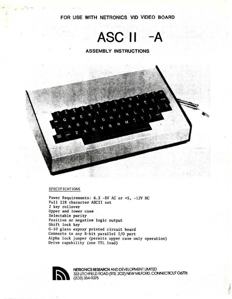
Netronics ASCII -A2 User manual

ASCII
-A2
ASSEMBLY
INSTRUCTIONS
SPECIFICATIONS
Power
Requirements:
+5V
&
-12V
DC
or
+5V
DC
&
6.3
to
8V
AC
Full
128
character
ASCII
set
2
key
rollover
Upper
and
lower
case
Selectable
parity
Positive
or
negative
logic
output
Shift
lock
key
G-10
glass
expoxy
printed
circuit
board
Connects
to
any
8-bit
parallel
I/O
port
Alpha
lock
jumper
(permits
upper
case
only
operation)
Drive
capability
(one
TTL
load)
NETRONICS
RESEARCH
AND
DEVELOPMENT
LIMITED
~\\
333
LITCHFIELD
ROAD
(RTE.
202)
NEW
MILFORD,
CONNECTICUT
06776
(203)
354-9375
|
REVISION
C

(
)
)
-0015
Disc
Capacitor
ASCII
KEYBOARD
ASSEMBLY
INSTRUCTIONS
Check
all
parts
in
your
kit
against
the
following
list.
Description
Quantity
KR2376-012
(Decoder
IC)
IN4001
(Diode)
IN4742A
(12V
Zener
Diode)
P.C.
Board
KB-2
150
ohm
Resistor
(Brown,
Green,
Brown)
4.7K
Resistor
(Yellow,
Violet,
Red)
680K
Resistor
(Blue,
Gray,
Yellow)
100K
Resistor
(Brown,
Black,
Orange)
56,
60
or
68pf
Disc
Capacitor
LOOMFD/16V
Capacitor
40
Pin
Socket
Momentary
Switches
Latching
Switch
Space
Bar
Return
Key
Miscellaneous
Key
Caps
(as
per
drawing)
Cable
Assembly
3
6"
14
lead
ribbon
cable
with
two
14
pin.
connectors
supplied
with
terminal
package.
O1
ul
BPE
H
HOE
NORE
EEE
OEE
PE
NE
3°14"
ribbon
cable
with
two
14
pin
connectors
supplied
with
stand
alone
ASCII
keyboard.
6
32x3/8"
Screw
3
6
32
Nut
3
Optional
Price
Deluxe
Steel
Cabinet
(blue
&
black)$19.95
+
$2.50
P&H
(Refer
to
Keyboard
Assembly
Figure)
DO
NOT
INSTALL
IC
UNTIL
POWER
CHECK
HAS
BEEN
MADE
1.
Install
40
pin
IC
socket
at
location
U-l.
(Solder).
2.
Install
key
switches.
Note:
Solder
one
lug
only.
The
second
lug
will
be
soldered
after
the
key
caps
have
been
installed
and
straightened.
The
shift
lock
key
is
the
latching
type
Switch
and
should
be
installed
first.
Note
that
two
momentary
Switches
are
used
for
the
space
bar.
3.
Install
key
caps.
4.
Check
alignment
of
keys
and
straighten
keys
by
heating
solder
connection
and
repositioning
switches.
Carefully
check
space
bar
action.

(
5.
Solder
remaining
unsoldered
switch
lugs.
6.
Install
resistor
R-1
150
ohm
(brown,
green,
brown).
Solder.
7.
Install
resistor
R-2,3,
4.7K
(yellow,
violet,
red).
Solder.
8.
Install
resistor
R-4
680K
(blue,
gray,
yellow).
Solder.
9.
Install
resistor
R-5
100K
(brown,
black,
yellow).
Solder.
)10.
Install
diode
CR1,
CR2
(IN4001).
NOTE:
Band
must
face
as
per
assembly
drawing.
)ll.
Install
diode
CR3
(IN4742A).
NOTE:
Band
must
face
as
per
assembly
drawing.
)1l2.
Install
C-2
.0015disc
capacitor.
Solder.
)13.
Install
C-4
56pf,
60
or
68pf
disc
capacitor.
Solder.
)14.
Install
C-1,3
100uf
capacitors.
Note
polarity.
Solder.
)
)
JUMPER
SELECTION
If
you
are
using
the
ASCII
keyboard
with
your
ELF
II
or
Explorer
85,
connect
jumpers
as
follows.
If
you
are
using
a
different
computer,
check
the
jumper
table
and
connect
as
per
your
requirements.
Connect
J2,
J4.
Solder.
Note
no
parity
signals
are
used
on
ELF
II.
or
Explorer.
:
JUMPER
TABLE
Jl
-
LOGIC
|J3
UPPER
&
LOWER
CASE|
J5
ODD
PARITY
J2
+
LOGIC
|J4
UPPER
CASE ONLY
J6
EVEN
PARITY
Solder
ribbon
cable
assembly
at
location
Pl
as
per
assembly
drawing.
Note
pin
#1
must
be
positioned
as
shown.
(A
socket
could
be
used
if
desired).
| ,
The
Netronics
ASCII
keyboard
can
be
used
with
any
number
of
computer
applications.
When
using
this
product
with
a
Netronics
computer
the
following
modifications
should
be
made
to
the
computer
to
facilitate
a
more
convenient
installation.
1.
When
using
the
ASCII
keyboard
ASCII
-
A2
with
a
Netronics
Video
Display
Board
make
the
following
modifications
to
your
Video
Display
Board.
Using
30
gauge
insulated
jumper
wire
connect
the
Jumper
between
J2
pin
7
and
U-4
pin
8.
Connect
an
insulated
jumper
between
J2
pin
8
and
U-4
pin
16.
Connect
the
jumper
between
J2
pin
9
and
the
-12V
terminal
at
the
edge
of
the
Video
Display
P.C.
Board.

-
Referring
to
the
interconnection
diagram
on
page
6
of
your
Video
Display
Board
manual
please
note
that
the
-12
and
the
ground
connections
between
the
Video
Display
Board
and
the
ASCII
keyboard
is
no
longer
required.
These
connections
are
now
made
via
the
14
pin
ribbon
cable.
3
2.
When
using
the
ASCII
keyboard
with
the
ELF
II
Giant
Board
make
the
following
modifications
to
your
Giant
Board.
Remove
the
jumper
or
diode
from
CR1.
Add
a
jumper
from
Al6
pin
8
to
AS5
pin
24.
Add
a
jumper
from
Al6
pin
7
to
All
pin
8.
Connect
the
3'
ribbon
cable
between
the
Giant
Board
and
ASCII
keyboard.
Connect
AC
supply
(6.3
to
8V
AC)
to
AC
input
on
the
ASCII
keyboard.
Observe
the
ground
polarity
if
you
are
uSing
the
Netronics
power
supply.
POWER
SUPPLY
TEST
(DO
NOT
INSTALL
U-1
YET)
Check
all
soldering
and
components
for
proper
value.
2;
Connect
the
ASCII
to
your
system.
1.
Measure
the
DC
voltage
at
pin
#1
&
18
of
socket
U-1.
The
voltages
should
be
+5V
&
-12V
respectively.
They
should
read
within
5%
of
the
specified
values.
Do
not
proceed
to
install
the
IC
if
the
voltage
is
improper.
2.
Disconnect
the
power
supply.
3.
install,
I¢G-1.
Note
location
of
pin.
#1.
WARRANTY
All
of
the
components
supplied
in
this
kit
are
under
warranty
for
Six
months
from
the
date
of
purchase.
Any
parts
suspected
to
be
defective
should
be
returned
to
Netronics
with
$1.00
for
postage
and
handling.
They
will
be
tested
and
returned
postpaid.
IN
CASE
OF
DIFFICULTY
In
the
event
of
difficulty,
check
all
wiring
against
the
instruc-
tions.
Check
for
solder
bridges
and
all
component
values.
If
you
still
cannot
determine
the
problem,
return
the
defective
printed
circuit
board
ONLY.
Please
enclose
a
check
or
money
order
for
$7.00
and
pack
the
board
securely,
and
insure
the
parcel.
Your
unit will
be
tested
and
returned
insured
and
postpaid.
Mailing
address:
NETRONICS
RESEARCH
&
DEVELOPMENT
LIMITED,
333
Litchfield
Road,
Rte.
202,
New
Milford,
Connecticut
06776,
Attention:
Service
Department.

Ritly|ul
GiWH
J
a
<
)
|
SSY
Sage
hs
Oe
ee

Ei
J
eal
sd
5
on
|
uO
VAC
LY
ia
=a
&
*Q
aa
.
|
O
He
>
By
4
NADA
WH
Ve
HIODMNMHAHOD
Bnd
Anwto
OIiImaaatm+vud¢ditagdgada
<
=
a
OHNM™
=
U
Eee
Ee)
ny
Geir
reEeecekeere
sc
ees
s&
2
le
ed
ed
ed
ed
ed
edd
ed ed
ed
ed
-d-r
sas
OI
wWemwAmadamaaawaAaAa
(.
~{2
UIl8
Ry
-
a
yo
J
J
O
oa
4
|
»
LL
+
“4
|
Tsyee
i)
an
-
a’
a
:
re
USC
Sle
=
A
|
ce
aw
KS
ce
elale
——
©
ze
areo
o/AABIE
SIE
fOFea
Si
zz
DOSMABME
—
mS
2g
ee
pe
se
Te
a
2
OO
IE
3
a
cee
z
|
a
SP
=]
0]
<]o]
f
3)
R4
GBOK
SCHEMATIC,
KEYBOARD
Table of contents
Other Netronics Keyboard manuals
