10
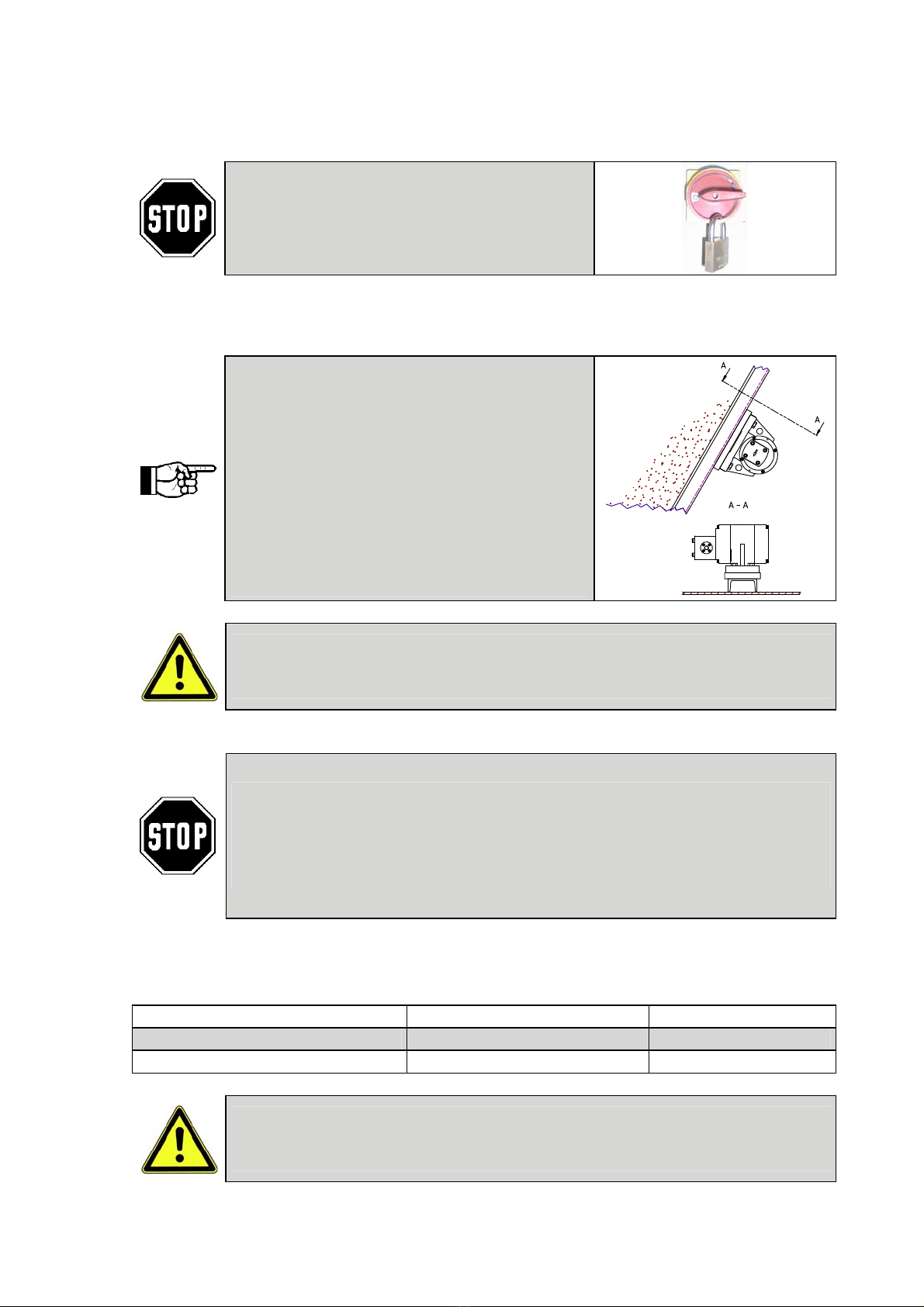
Direction of rotation:
Hydraulic vibrators of type NHG without leak oil port must only be operated
with the specified direction of rotation. With these units a loading of the
return flow with system pressure must be ruled out.
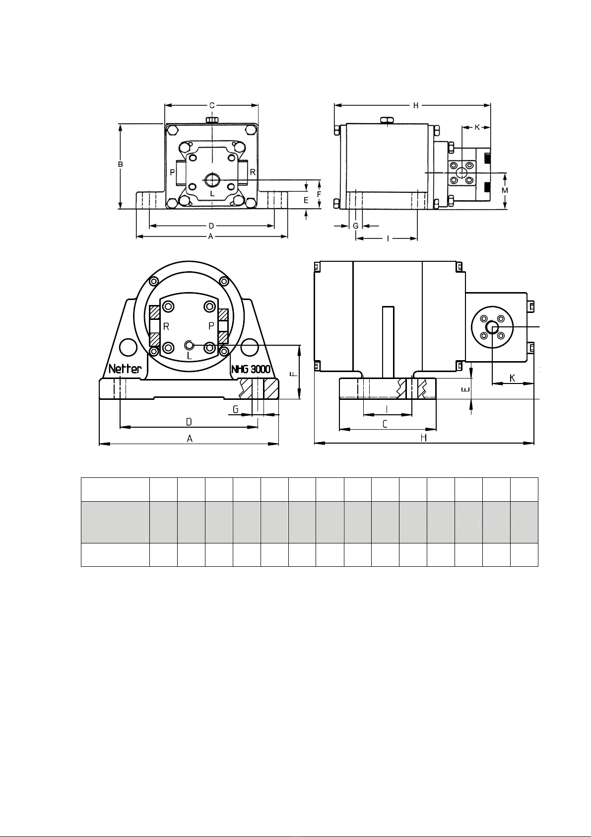
Connecting data
Pressure Return side Leakage line
Type Thread NW [mm] Thread NW[mm] Thread NW[mm]
NHG 500 G 1/4 8-12 G 3/8 12-15 - -
NHG 600 R G 1/4 8-12 G 3/8 12-15 - -
NHG 900 G 1/4 8-12 G 3/8 12-15 - -
NHG 3000 G 3/8 12-15 G 1/2 15-18 - -
NHG 500 L G 1/4 8-12 G 3/8 12-15 G 1/48
NHG 600 R L G 1/4 8-12 G 3/8 12-15 G 1/48
NHG 900 L G 1/4 8-12 G 3/8 12-15 G 1/48
NHG 3000 L G 3/8 12-15 G 1/2 15-18 M12×1,5 8
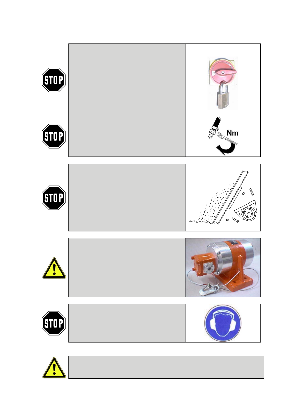
Checklist for installation:
1)
2)
3)
4)
Consider the expected operating temperature.
Tighten the fastening screws for the NHG.
Assemble way and flow control valve, supply, return and by-pass lines.
Check!
Has the direction of rotation of the hydraulic motor been observed?
Have the hoses been tightened?
Have the specifications on nominal diameters been observed?
Has the unit been secured against falling down?
7 Operation
Flushing:
Before starting hydraulic external
vibrators all corrosion protection
residues or impurities that have
entered during transport and storage
must be flushed out with the hydraulic
fluid to be used.
Filter:
During the running-in phase use a
filter R5μm for 2-3 hours, then
change to R10μm (19/16 ISO 4406).
Leak oil port:
If NHG have to be operated with
higher pressures in the return flow, the
version with leak oil port must be used
(for permissible operating pressures
refer to chapter 4 safety page 7).
The leakage line must be routed in a
size and should end in the tank below
the fluid level, so that the unit stays
filled, but no siphon effect is created
inside the tank.
Direction of rotation:
Hydraulic external vibrators without
leak oil port (L) have only one
permissible direction of rotation. A
change in the direction of rotation can
only be made by Netter GmbH.
Hydraulic external vibrators with
leakage port can be used for both
directions of rotation.
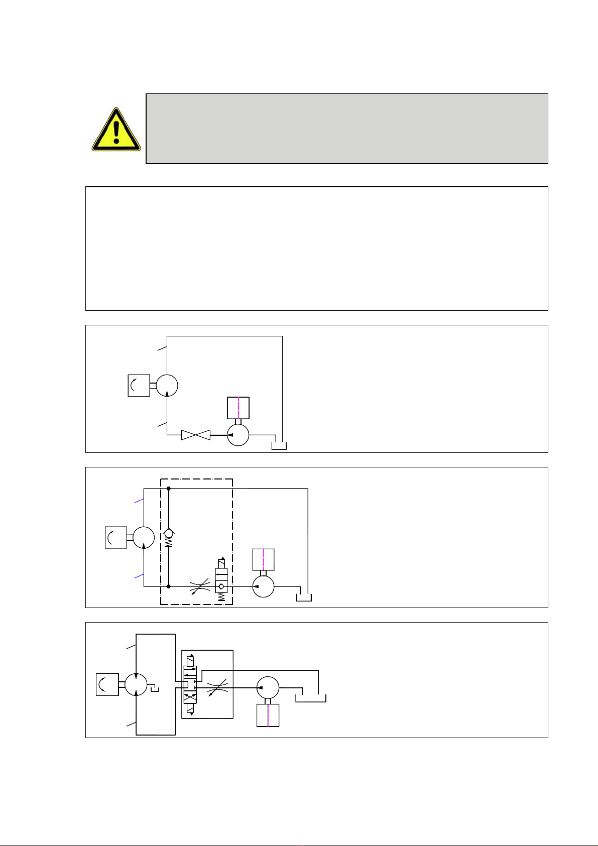
Regulating the speed:
Regulation of the speed can only be
accomplished by an external control
with adjustable flow control valve.
Possible controls see chapter 6
"Assembly” on page 9.