HIAB K-HiPro 285-425-4 Series User manual

HIAB K-HiPro 285-425
X4
Operator's Manual GB
This operator’s manual is an Original Instruction and applies to cranes with serial numbers from:
2851001, 4250001.
2018-12

Congratulations with your new crane!
You are now the owner of a quality product from Cargotec, built to the highest
standards of safety and quality.
The aim of this manual is to help you handle your crane safely and with full
satisfaction.
Please read the complete manual. It provides detailed information about the
crane, control system and the practical management and maintenance of the
crane.
We advise you to read it carefully and familiarize yourself with your crane
before you start to use it.
Help us to improve this manual. Please send your comments and
suggestions to [email protected]
This manual includes interactive contents.
Download the 'Hiab AR+ App' for the interactive content in this manual.
Look for the AR+ symbol. Use your device to scan the image next to the
symbol.
The interactive contents in the Hiab AR+ App will display suggestions to
make the crane operation easier for you to understand. However, note that
some of the content included in the 'Hiab AR+ App' may differ from the
actual configuration of your crane and is subject to updates and changes
from Hiab without prior notice.

Table of Contents
1. Introduction ......................................................................................... 7
1.1. This Operator's Manual is intended for operators of this HIAB crane. ............ 7
1.2. Cleanliness certificate ................................................................... 8
1.3. Indications in the Operator’s Manual .................................................. 8
2. Structure and parts of the HIAB crane ........................................................ 11
2.1. Main groups ............................................................................ 11
2.2. Crane base with column and slewing system ...................................... 11
2.3. Stabiliser system ...................................................................... 11
2.4. Boom system .......................................................................... 12
2.5. Accessories on the boom system ................................................... 12
2.6. Operating system - hydraulic components ......................................... 14
2.7. LHV Load holding valves ............................................................. 15
2.8. Description of HIAB K-HiPro 285-425 ............................................... 15
3. Safety precautions and warnings .............................................................. 16
3.1. Operating conditions .................................................................. 16
3.2. Wind speeds ........................................................................... 17
3.3. Definition of a HIAB loader crane .................................................... 17
3.3.1. Noise declaration ............................................................ 18
3.3.2. Signs on the crane .......................................................... 19
3.3.3. Maximum load [AR+] ........................................................ 19
3.3.4. Maximum load moment ..................................................... 21
3.4. Signals when using a crane [AR+] .................................................. 23
3.5. Use of the crane ....................................................................... 26
3.5.1. Preparations for use ........................................................ 28
3.5.2. Crane operation ............................................................. 29
3.5.3. Driving with the crane ....................................................... 32
3.5.4. Use of lifting equipment .................................................... 33
3.5.5. Use of demountable cranes ................................................ 33
3.5.6. Ending crane operation ..................................................... 34
4. The HiPro system ................................................................................ 35
4.1. Control System SPACE X4 ........................................................... 35
4.2. How the safety system works ........................................................ 35
4.3. Components of the HiPro system ................................................... 36
4.4. Standard symbols and functions of the crane and the stabiliser system ........ 37
4.5. Main control valve ..................................................................... 38
4.6. Different stabiliser control valves .................................................... 39
4.7. User panel .............................................................................. 39
4.7.1. Indicator LEDs on user panel .............................................. 39
4.8. Dump valves ........................................................................... 41
4.9. Selector valve [option] ................................................................ 42
4.10. Pressure-reducer filter ............................................................... 42
4.11. Warning lamps ....................................................................... 42
4.12. XSDrive controller .................................................................... 43
4.12.1. Indicator LEDs on XSDrive controller ................................... 44
4.12.2. Buttons ...................................................................... 45
4.12.3. Menus ....................................................................... 46
4.12.4. Standard functions and symbols ......................................... 47
HIAB K-HiPro 285-425 X4 3

4.12.5. Battery and battery charger XSDrive .................................... 48
4.13. CombiDrive controller ............................................................... 49
4.13.1. Displays ..................................................................... 49
4.13.2. Buttons ...................................................................... 52
4.13.3. Menus, standard functions and symbols ................................ 53
4.13.4. Battery and battery charger ............................................... 57
4.14. Cranes with high seat [option] ...................................................... 59
5. Starting crane operation ........................................................................ 60
5.1. Starting operations [AR+] ............................................................. 60
5.2. Set the stabiliser system .............................................................. 63
5.2.1. Stabiliser system and ground conditions ................................. 64
5.2.2. Activate the stabiliser system .............................................. 65
5.2.3. Extend the stabiliser extensions ........................................... 65
5.2.4. Set the stabiliser legs [AR+] ................................................ 66
5.3. Operate the boom system out of transport position ............................... 67
6. During operation ................................................................................. 70
6.1. Features ................................................................................ 70
6.1.1. Controlling the crane speed with the controller XSDrive ................ 70
6.1.2. Controlling the crane speed with the controller CombiDrive ........... 70
6.1.3. Supervision of spools ....................................................... 71
6.1.4. CTC Crane Tip Control [option] ............................................ 71
6.1.5. APO Automatic power off .................................................. 72
6.1.6. ADO Automatic dump function ............................................ 72
6.1.7. ASC Automatic Speed Control ............................................ 72
6.1.8. ADC Automatic Duty Control ............................................... 73
6.1.9. PFD Pump flow distribution ................................................ 73
6.1.10. Slewing sector [option] .................................................... 73
6.1.11. VSL Variable Stability Logic [option] ..................................... 74
6.1.12. VSL+ (Variable Stability Logic Plus) [option] ........................... 74
6.1.13. LSS-V Load stabilising system-vertical [Option] ....................... 75
6.2. OLP (Overload protection) ........................................................... 75
6.3. OLP - indications on the controller .................................................. 77
6.4. To release OLP ........................................................................ 78
7. Ending crane operation ......................................................................... 80
7.1. Operate the boom system into transport position .................................. 80
7.2. Placing the stabiliser system in the transport position [AR+] ..................... 81
7.3. Switching off the control system ..................................................... 83
7.4. Emergency operation Valve-V200 ................................................... 83
7.5. TWI Transport warning interface [option] ........................................... 84
8. Maintenance and Service ....................................................................... 86
8.1. Service .................................................................................. 86
8.2. Warranty ................................................................................ 87
8.3. Follow the maintenance instructions! ............................................... 88
8.3.1. Daily inspection .............................................................. 89
8.3.2. Monthly inspection and maintenance ..................................... 92
8.3.3. Annual maintenance ........................................................ 93
8.4. Lubrication .............................................................................. 93
8.4.1. Lubrication schedule [AR+] ................................................ 94
8.4.2. Lubrication of the upper column bearing ................................. 95
8.4.3. Lubrication of slide pads in boom system ................................ 95
4 HIAB K-HiPro 285-425 X4

8.4.4. Lubrication of the hooks .................................................... 95
8.5. Hydraulics .............................................................................. 96
8.5.1. Slewing housing: checking the oil level/oil change ...................... 96
8.5.2. Checking the oil tank level ................................................. 97
8.5.3. Changing the hydraulic oil .................................................. 97
8.5.4. Bleeding air from the hydraulic system ................................... 99
8.5.5. Replacement of filters ...................................................... 100
8.5.6. Replacing the cartridge in high pressure filter .......................... 101
8.5.7. Replacing the cartridge in pressure-reducer filter - V200 .............. 102
8.5.8. Replacing the cartridge in return oil filter ................................ 103
8.6. Troubleshooting ...................................................................... 104
8.6.1. Main fuses .................................................................. 104
8.6.2. Faults on the crane ......................................................... 105
8.6.3. Display [option] ............................................................. 108
9. Decommissioning ............................................................................... 110
9.1. Decommissioning a crane ........................................................... 110
10. Technical Data ................................................................................. 112
10.1. Load plate table ..................................................................... 112
10.2. Identification of the loader crane .................................................. 113
10.3. Abbreviations ........................................................................ 113
10.4. Daily inspection checklist to photocopy .......................................... 114
HIAB K-HiPro 285-425 X4 5

This page is intentionally left blank.
HIAB K-HiPro 285-425 X4
1. Introduction
1.1. This Operator's Manual is intended for operators of this
HIAB crane.
This manual describes:
• Operation
• Safety precautions and warnings
• The crane control system
• Maintenance and troubleshooting
Enclosed to this manual the Installer will provide:
• Technical Data for your crane
• Technical Data and manuals for add on equipment if fitted
Study these instructions carefully
DANGER
If you do not study the complete Operator’s Manual for your crane carefully, it
could lead to fatal accidents or serious damage.
Therefore you should:
• Study the entire Operator’s Manual carefully.
• Study the operating manuals for other add-on equipment,
if fitted.
• Use the crane only after having done so.
• Follow the directions for use, operation and maintenance
of the crane and add on equipment exactly.
• Store the Technical Data and manuals from the Installer,
together with this Operator's manual.
NOTE
The manufacturer reserves the right to change specifications, equipment,
operating instructions and maintenance instructions without prior notice.
Introduction
HIAB K-HiPro 285-425 X4 7

NOTE
HIAB shall at all times have the right to:
• install, maintain and dismantle automated remote diagnostics system or similar
sensor-based system (the “System”) in and from the Equipment; and
• access, send, receive, collect, store and use any and all information and data
gathered or created by such System including but not limited to information
concerning operation, operating environment, movement, condition, logon,
location and similar information relating to the Equipment (the “Information”).
The Customer shall not in any way remove or alter the System, nor interfere with
the use of the System or the Information. The System and the Information and all
their further developments shall at all times be and remain the exclusive property
of HIAB without granting any right or license to the customer.
1.2. Cleanliness certificate
All Hiab equipment has been tested and certified at the
factory according to the Hiab Standard C250.52 that
defines the Cleanliness Requirements for Hydraulic
Systems. This means that they fulfil the cleanliness class
20/18/14 measured by the ISO 4406 standard.
All hydraulic functions have been individually tested and
fully comply with the defined requirements.
1.3. Indications in the Operator’s Manual
What must you do and not do?
The following indications are used in the Operator’s Manual:
DANGER
Danger to life for yourself or to bystanders.
Follow the instructions carefully!
WARNING
Danger of injury to yourself or to bystanders, or danger of serious damage to the
crane or other objects.
Follow the instructions carefully.
CAUTION
Hazard for the crane or crane components. Follow the instructions carefully.
Introduction
8 HIAB K-HiPro 285-425 X4
Important:
If actions are numbered
1. Do this
2. Do that
3. ......
4. .....
5. .....
you should carry them out in numerical order!
NOTE
Extra information that can prevent problems.
TIP
Tip to make the work easier to carry out.
Symbol for reference to a component in an illustration.
(1) Refers to a component in an illustration.
[option]: Indication for parts that are not-standard for the
crane, but are an option. Not all [option] are available for
your crane.
DANGER
Only persons with the requisite knowledge and experience with cranes may use
the crane. Never operate the crane when you are sick, tired, under the influence of
medicines, alcohol or other drugs.
• Take the delivery instructions from your HIAB Service workshop, or receive instruction from an
experienced person from your own company. Only then should you operate your crane.
• Ensure that you comply with the statutory requirements of the country in which you use the crane
(for example, certificate, obligatory safety-helmet).
1
Introduction
HIAB K-HiPro 285-425 X4 9
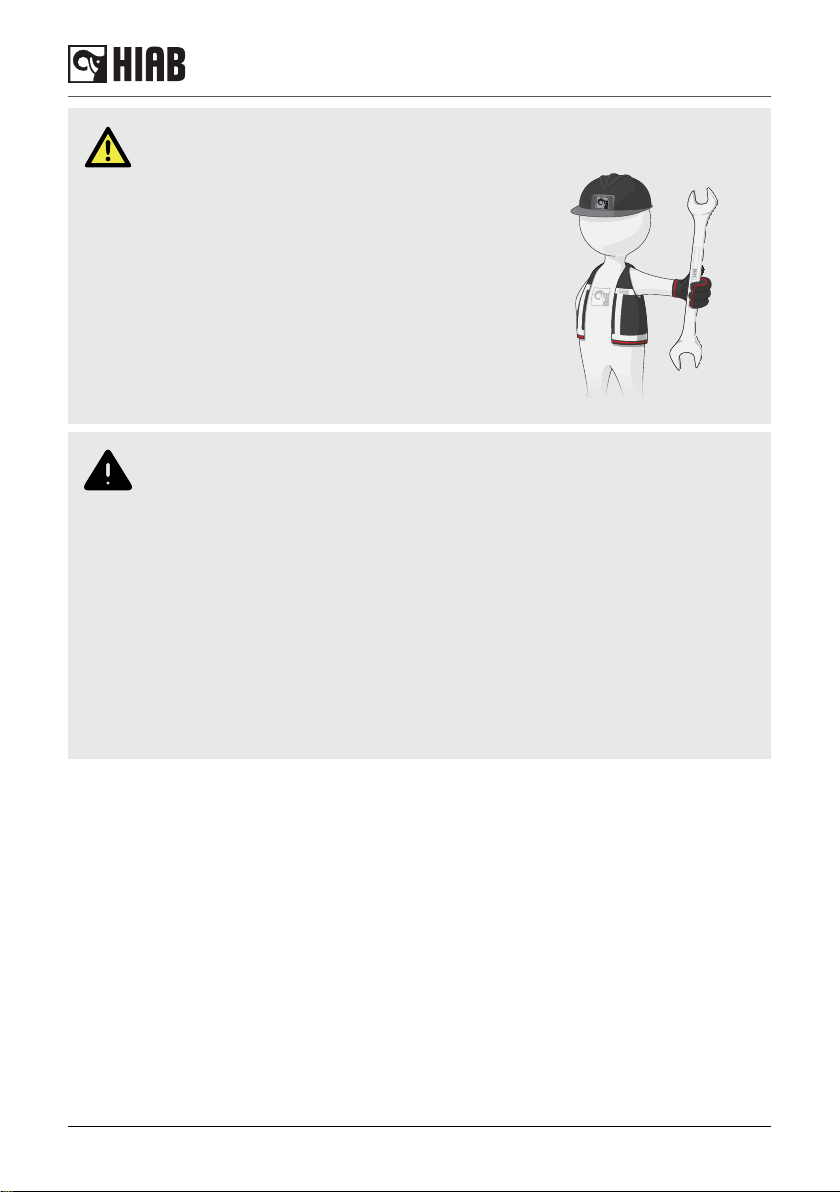
DANGER
• Carry out yourself only the service and
maintenance work you have the requisite
knowledge and experience of.
• All other maintenance work may only be
carried out by a HIAB service workshop.
• Ensure that every defect is rectified
immediately, according to the instructions.
• Follow the instructions exactly!
• All other work to rectify faults must be
performed by personnel in a HIAB service
workshop!
WARNING
• Never clean the electronic system, plastic components, signs or bearings with a
high-pressure jet cleaner. It could cause damage.
• Never expose the electronic system to high electrical voltages. This could
damage the control system.
• Never immerse the controller in water or other liquid. This will make the
controller unusable.
If your crane is equipped with add-on lifting equipment (hoist, rotator, etc.):
• The operation of the crane with add-on lifting equipment can differ from the
operation as described in this manual.
• You should therefore study the Operating Manual for the add-on equipment
carefully, before you use the crane.
• Take particular note when placing the crane in to or out of transport position.
Introduction
10 HIAB K-HiPro 285-425 X4
2. Structure and parts of the HIAB crane
2.1. Main groups
The HIAB crane consists of the following main groups:
• Crane base with column and slewing system
• Stabiliser system
• Boom system
• Operating system - hydraulic components
Some accessories can be fitted depending on your crane configuration:
• Add-on lifting accessories [option]
• Hooks [option]
• Separate lifting accessories [option]
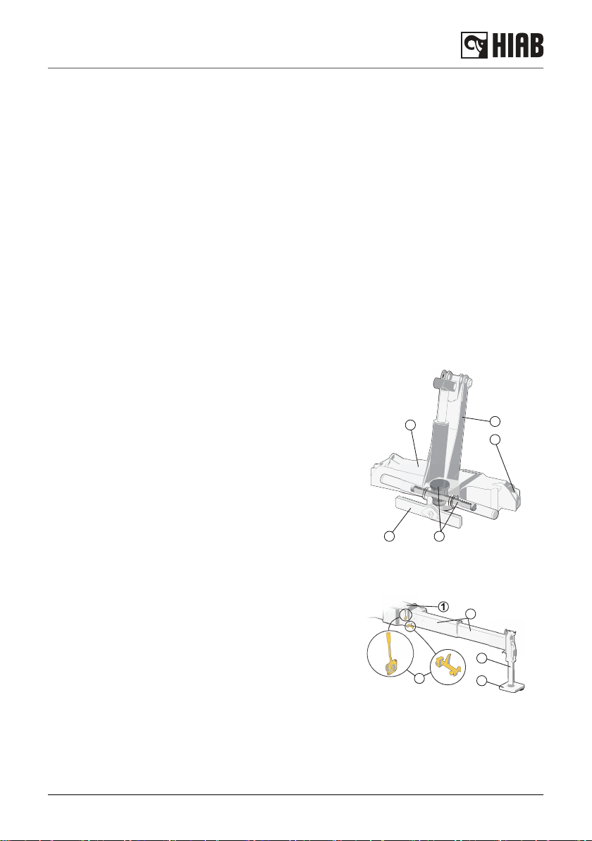
2.2. Crane base with column and slewing system
The crane base, column and the slewing system consist of
the following components:
(1) Crane base
with stabiliser beams (2) and three-point bridge (3)
(4) Column
fitted to the crane base
(5) Rack and pinion slewing system
2.3. Stabiliser system
Every HIAB crane is equiped with two stabiliser extensions
and two stabiliser legs. Auxiliary stabiliser systems may be
needed for heavy cranes. The stabiliser system consists of:
(1) Stabiliser beam
(2) Stabiliser extensions
(3) Stabiliser legs
(4) Stabiliser locking devices [option]
(5) Extra support plates
1
2
3
4
5
1
2
3
4
5
Structure and parts of the HIAB crane
HIAB K-HiPro 285-425 X4 11
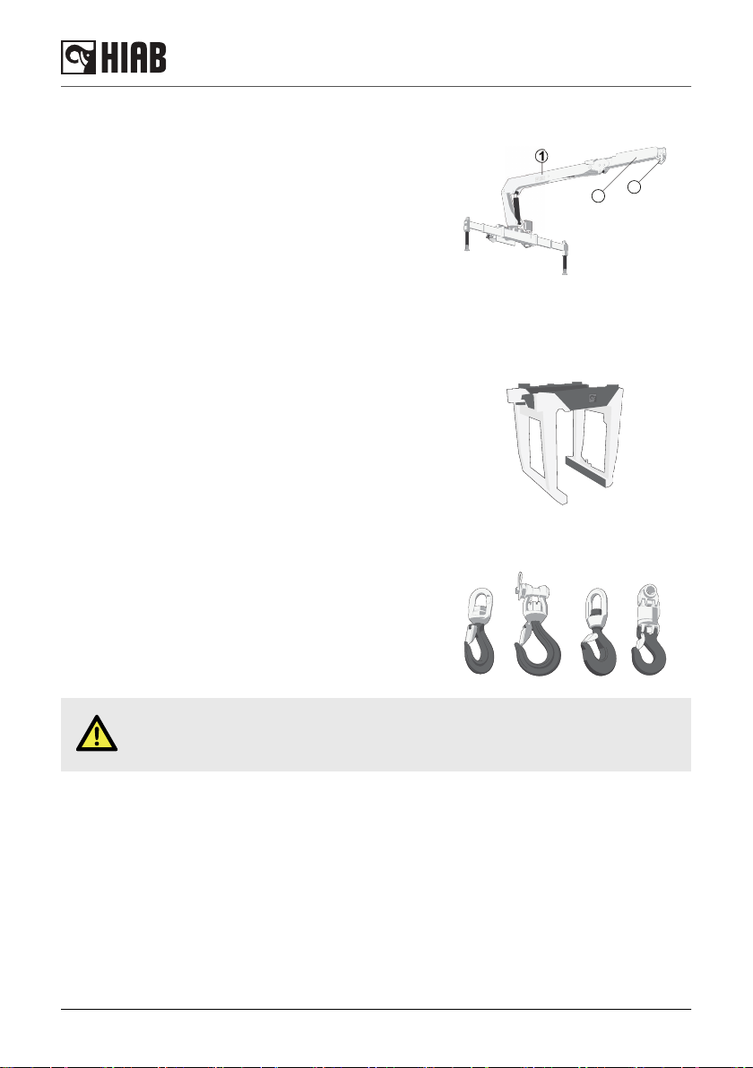
2.4. Boom system
The boom system consists of the following components:
(1) 1st boom
(2) 2nd boom
(3) Hydraulic extensions
The extensions are operated by hydraulic cylinders placed
inside the extensions.
2.5. Accessories on the boom system
Add-on lifting accessories [option]
Add-on lifting accessories are placed between the boom tip
and the load (e.g. brick grapple, rotator) or on the crane
(hoist).
Hooks [option]
Different hooks can be mounted depending on the crane
model.
DANGER
Never exceed the maximum permissible loading of the hook.
1
23
Structure and parts of the HIAB crane
12 HIAB K-HiPro 285-425 X4

Separate lifting accessories [option]
Separate lifting accessories, help to make or use a slinging
device: eye-hooks, shackles, eye-bolts etc.
Structure and parts of the HIAB crane
HIAB K-HiPro 285-425 X4 13
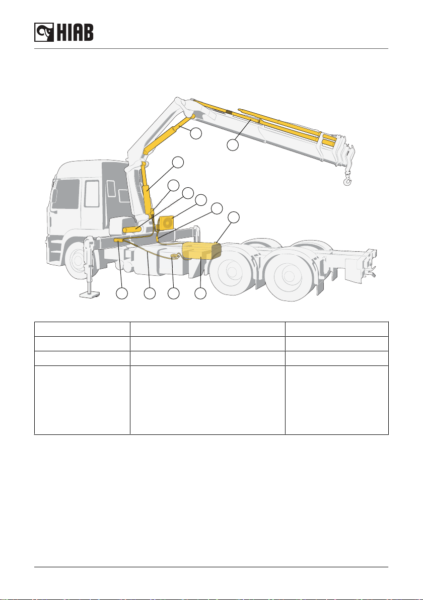
2.6. Operating system - hydraulic components
The operating system consists of the following hydraulic components:
12
3
4
5
6
7
8
9
10
11
12
(1) Oil tank (5) Stabiliser control valve [option] (11) Return filter
(2) Hydraulic pump (6) Hydraulic hoses and lines (12) Load holding valve
(3) Oil cooler [option] (7) Slewing cylinders / Motor reducers Pressure filter [option]
(4) Main control valve Actuators:
(8) First boom cylinder
(9) Second boom cylinder
(10) Extension cylinder/s
Structure and parts of the HIAB crane
14 HIAB K-HiPro 285-425 X4

2.7. LHV Load holding valves
All cylinders are equipped with load-holding valves as a
safety device. After a crane movement they hold the crane
in position, also in the unlikely event of a burst hose.
If there is a leak or a component fractures, such as a pipe,
hose or a coupling, the load-holding valves will stop the
booms from collapsing down, even when the hydraulic
system is switched off, and you operate a particular crane
function.
To operate a hydraulic cylinder equiped with a load holding
valve, an opening pressure is required.
2.8. Description of HIAB K-HiPro 285-425
The HIAB K-HiPro 285-425 are compact, fully hydraulically operated goods cranes.
Lifting capacity:
• HIAB K-HiPro 285 = 25.5 tonne metres (184 400 ft-lbs)
• HIAB K-HiPro 425 = 34 tonne metres (245 900 ft-lbs)
The crane is supplied in many versions from:
• HIAB K-HiPro 285-2 reach: 13.6 metres (44' 5" ft)
• HIAB K-HiPro 285-3 reach: 16.1 metres (52' 10" ft)
• HIAB K-HiPro 425-4 reach: 19.1 metres (62' 8'' ft)
The control valve V200, a controller (CombiDrive or XSDrive) and the SPACE X4 safety system are
standard equipment on the HIAB K-HiPro 285/425.
The crane type and the manufacturer are marked on the serial number plate.
NOTE
The exact technical information for your crane is shown in the Technical Data.
Structure and parts of the HIAB crane
HIAB K-HiPro 285-425 X4 15

3. Safety precautions and warnings
3.1. Operating conditions
You may only use the crane under the following conditions:
• In the open air, or in spaces with sufficient ventilation.
• With a mean wind velocity less than 13.3 m/sec (approx. 29.7 mph). See the wind speed table.
DANGER
• If you use the crane in a confined space you could suffocate from the exhaust
gases from the vehicle.
• Never use the crane in a high wind or storm. When the mean wind velocity
exceeds 13.3 m/sec (approx. 29.7 mph) the crane will behave unpredictably.
Never use the crane during a thunderstorm.
•Never use the crane at temperatures below -40°C (-40°F), as the steel's
properties deteriorate below this temperature.
WARNING
• At temperatures below 0°C (32°F):
Do not touch the operating levers during
the first few minutes.
• When starting in cold weather, the wear on
the hydraulic system is greater than at
normal working temperatures.
To get a good function of the crane, it should
be started as follows:
• Engage the power take-off at low rpm.
• Allow the system to idle for a few minutes.
• Operate stabiliser legs up and down for
one minute, in order to warm up the oil.
Safety precautions and warnings
16 HIAB K-HiPro 285-425 X4

3.2. Wind speeds
Wind speed averaged over 10 minutes at a height of 10 m
Wind
Force
Above flat ground Characteristics
m/s Wind type
0 0.0 - 0.2 Calm Calm, smoke rises vertically or nearly
vertically
1
2
0.3 - 1.5
1.6 - 3.3
Slight breeze Wind direction recognisable from smoke
plumes, the wind begins to be noticeable on
the face; leaves begin to rustle and weather
vanes can start to move.
3
4
3.4 - 5.4
5.5 - 7.9
Moderate wind Leaves and twigs in continuous movement,
small branches begin to move. Dust and
paper begin to move over the ground.
5 8.0 - 10.7
Fairly strong
wind
Small leaved branches make swaying
movements; crested waves form on lakes
and canals.
6 10.8 - 13.8
Strong wind Large branches move; you can hear the
wind whistling in telephone wires; umbrellas
can only be held with difficulty.
7 13.9 - 17.1 Severe wind Entire trees move; the wind causes difficulty
when you walk into it.
8 17.2 - 20.7 Stormy wind Twigs break off, walking is difficult.
9 20.8 - 24.4
Storm Causes superficial damage to buildings
(chimney pots, roof-tiles, and TV antennae
are blown off).
10 24.5 - 28.4 Severe storm Uprooted trees; considerable damage to
buildings etc. (occurs infrequently on land).
11 28.5 - 32.6 Very severe
storm
Causes extensive damage (occurs very infre
quently on land).
12 > 32.6 Hurricane
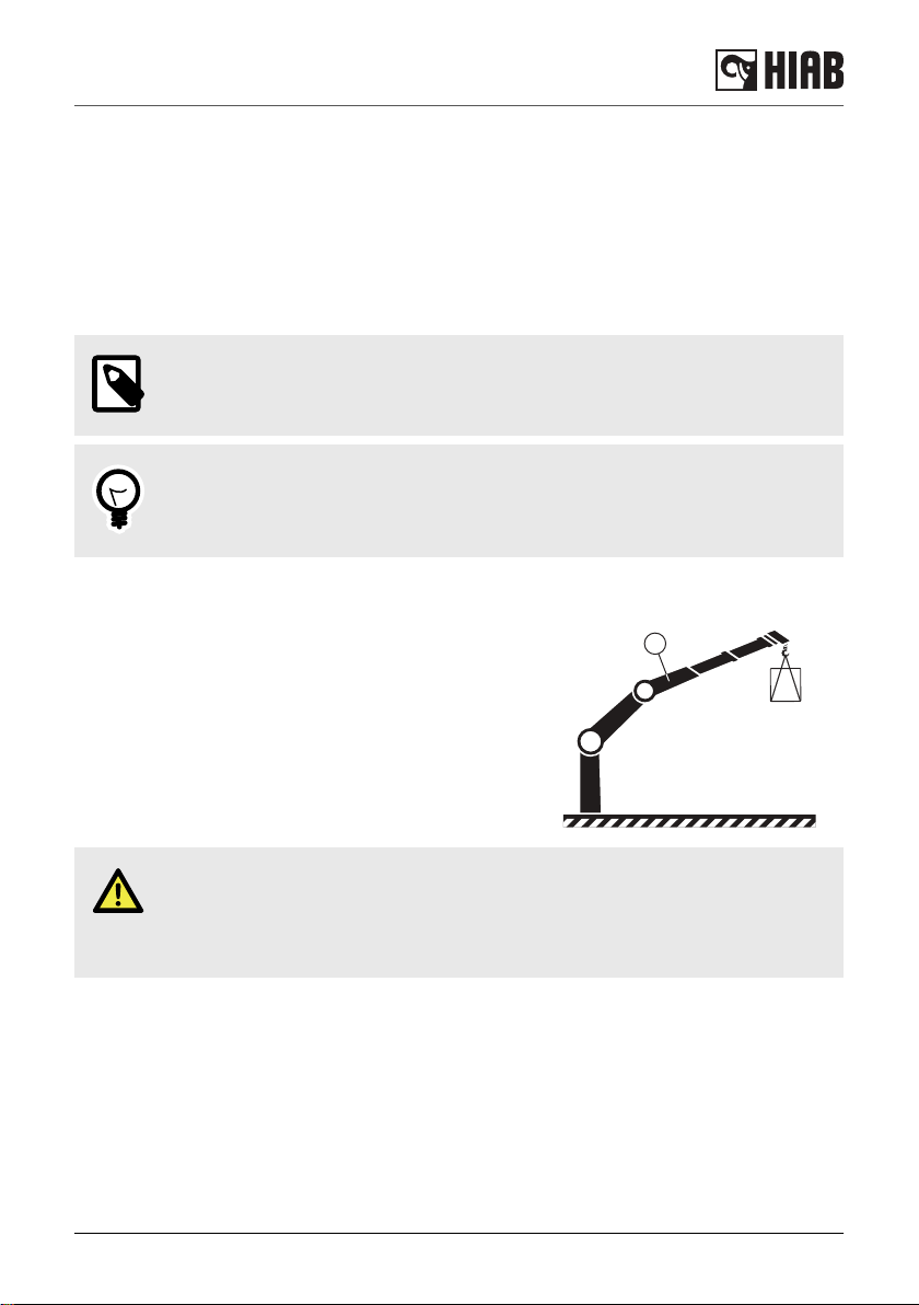
3.3. Definition of a HIAB loader crane
Usage of the crane
The HIAB loader crane is used to lift and move loads in the working area permitted by the load
plate and the load diagram. The cranes are normally mounted on a vehicle but they can also be
mounted on a fixed base plate. The crane can be equipped with a number of accessories.
Loader cranes are designed for loading and unloading the vehicle, as well as for other duties as
specified:
Safety precautions and warnings
HIAB K-HiPro 285-425 X4 17

Permitted duties:
• Loading and unloading cargo from/to a vehicle
• Lifting of loads from the ground/vehicle to a higher place
• Installation work (beams, concrete plates, windows...) in building constructions
• Lifting construction material (wall boards, bricks, blocks…) on a pallet fork to a building, taking
the material from the vehicle on which the crane is mounted, from another vehicle or from the
ground
• Hoisting, e.g. beams, concrete plates and any other material and equipment used in building
construction
• With a bucket, moving filling material at a construction site
• Handling large loads (containers, boats, machinery, vehicles…)
• Collection of waste and recycling material (glass, paper, cardboard, plastic…)
• Installation of informative posts, road signs, notice boards, traffic lights, street lights…
Forbidden duties:
• Crane mounted onboard ships or floating structures, only permitted in cases authorized by HIAB
• Continuous use as a production crane in assembly lines, foundries…, except for cranes prepared
for that purpose
• Handle loads, work with submerge boom system or accessories, in strong currents such as
rivers
• Loading cargo that is partially loaded or fastened by other means, without making sure the
capacity of the crane is enough for the entire load
• Any duty which implies:
◦ Pressure against the ground, unless the crane is specifically prepared for this
◦ Push/pull with the boom system against any type of obstacle (wall, ground…)
DANGER
Lifting people with a crane is never allowed unless it is a MEWP crane.
3.3.1. Noise declaration
The following values for emitted noise may be taken as general and conservative values for
ordinary installations of loader cranes on normal diesel engine powered trucks. Declared dual-
number noise emission values in accordance with ISO 4871:
• Emitted A-weighted sound power level for basic loader cranes in accordance with ISO 3744:
LwA = 103 dB (Uncertainty: KwA = 2 dB).
• Emitted A-weighted sound power level for loader cranes with hoist in accordance with ISO 3744:
LwA = 107 dB (Uncertainty: KwA = 2 dB).
• A-weighted sound pressure level at loader crane control stations in accordance with ISO 11201:
LpA = 95 dB (Uncertainty: KpA = 4 dB).
Particular installations can be quieter, in which case a post installation noise measurement in
accordance with clause 6.3 of EN 12999:2011 may be used to prove this.
Safety precautions and warnings
18 HIAB K-HiPro 285-425 X4
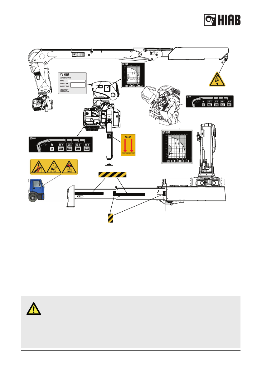
3.3.2. Signs on the crane
3.3.3. Maximum load [AR+]
Lifting capacity
Your crane has a certain lifting capacity, expressed in kNm, tm or fts-lbs. This lifting capacity is also
known as the load moment. The lifting capacity is: the payload at hook multiplied by the outreach in
metres that the crane can operate at different positions. The lifting capacity of your crane
determines the maximum load your crane may lift within its working zone. However take careful
note; the greater the operating radius of the crane, the lower the lifting capacity will be because of
the weight of the boom system itself. The load plate and the load diagram on your crane show the
maximum loads you may lift in the operating reach of your crane.
DANGER
• Overloading could result in damage to the crane or in the worst case, personal
injury or death.
• Never increase a hanging load, since that may cause a load holding valve to
open and/or the vehicle to turn over.
• Never use the crane with the OLP system switched off.
Safety precautions and warnings
HIAB K-HiPro 285-425 X4 19

NOTE
The extra weight of the lifting accessories has to be added to the load. Thus, with
lifting accessories the load you can lift is less heavy
Load plate
You will find the load plate next to the control valve. On the
plate is the maximum weight that you may lift at a given
reach, with the 1st boom in the optimum position. In
chapter Technical Data in this manual you will find these
values for your crane.
Optimum position
The weight that your crane can lift will be determined by:
• Stabilty test of your crane on vehicle [if VSL as option]
• Stabiliser extensions positioned and legs pressed to ground.
• The reach at which you are working and the optimum position of the boom.
• The optimal position for your crane is on the load plate.
DANGER
Never exceed the maximum weight on the load plate.
Load diagram
The load diagrams are placed on the column and show the maximum loads your crane may lift in
the entire working zone. The load diagram drawing will also be found in the enclosed Technical
Data.
The white area is the working zone of the crane.
The load curves show the maximum load that may be lifted at a given reach and height. For a
given maximum load, the possible working zone is to the left of the load curve. The lifting capacity
for some cranes is limited in the high lifting area.
XXXX XXXX XXXX XXXX
XXXX XXXX
XX´X´´ XX´X´´ XX´X´´ XX´X´´
XXXX XXXX
Safety precautions and warnings
20 HIAB K-HiPro 285-425 X4
Table of contents
Other HIAB Construction Equipment manuals

HIAB
HIAB 335K HiPro CD CE User manual

HIAB
HIAB K-HiPro 505 X4 User manual

HIAB
HIAB HIAB T-HiDuo 013 CE User manual

HIAB
HIAB X-HiPro 358-408-418 X4 User manual

HIAB
HIAB 322 HiPro CD User manual

HIAB
HIAB 422-477 HiPro CD User manual

HIAB
HIAB X-Duo 044 User manual

HIAB
HIAB J14S User manual

HIAB
HIAB 335K HiPro CD CE User manual

HIAB
HIAB 160TM Guide


