Network Devices ND-88-18GB User manual

8x8 HDMI 18Gbps Matrix with
Audio De-embedded
VER 1.0

1/12
Thank you for purchasing this product
Surge protection device recommended
Table of Contents
For optimum performance and safety, please read these instructions caref-
ully before connecting, operating or adjusting this product. Please keep this
manual for future reference.
This product contains sensitive electrical components that may be damaged
by electrical spikes, surges, electric shook, lighting strikes, etc. Use of surge
protection systems is highly recommended in order to protect and extend the
life of your equipment.
1. Introduction.........................................................................................
2. Features...............................................................................................
3. Package Contents..............................................................................
4. Specifications......................................................................................
5. Operation Controls and Functions....................................................
5.1. Front Panel..................................................................................
5.2. Rear Panel..................................................................................
6. Detail description of display mode...................................................
7. Remote Control...................................................................................
8. Web GUI User Guider..........................................................................
9. Application Example..........................................................................
2
2
2
3
4
4
5
6
8
9
12
1/12

1. Introduction
2. Features
3. Package Contents
The 8x8 HDMI Matrix supports the transmission of video (up to 4K2K@60Hz
YUV 4:4:4, 18Gbps, HDCP 2.2) and multi-channel digital audio from 8 HDMI
sources to 8 HDMI displays. Audio de-embedded is supported from 8 HDMI
output ports. Control is via button, IR, RS-232, LAN and Web GUI.
☆HDMI 2.0b, HDCP 2.2 and HDCP 1.4 compliant
☆Up to 4K2K@60Hz (YUV 4:4:4) on all HDMI ports
☆Supports pass-through audio up to 7.1 channels of High Definition audio
(LPCM, Dolby TrueHD, and DTS-HD Master Audio)
☆Audio de-embedded is supported via coax port
☆HDR, CEC and smart EDID management supported
☆Control is via on-panel Button, IR, RS-232, LAN and Web UI
☆1U rack mounted design with aluminum front panel
①1x 8x8 HDMI Matrix
②1x 12V/3A Locking Power Adaptor
③1x Remote Control
④1x Wideband IR Receiver cable
⑤1x RS-232 male to female serial cable
⑥1x User Manual
2/12

4. Specifications
Technical
HDMI Compliance HDMI 2.0b
HDCP Compliance HDCP 2.2 and HDCP 1.4
Video Bandwidth 18Gbps
4K2K@60Hz (YUV 4:4:4)
Color Depth 8-bit, 12-bit
HDMI Audio
Formats
Connections
Outputs
Mechanical
3.35kg
Input: AC100~240V 50/60Hz, Output: DC12V/3A
(US/EU standards, CE/FCC/UL certified)
26.5W (max)
0°C ~ 40°C / 32°F ~ 104°F
-20°C ~ 60°C / -4°F ~ 140°F
ESD Protection Human-body Model:
±8kV (Air-gap discharge) , ±4kV (Contact discharge)
Power Supply
Dimensions
Weight
Metal Enclosure
Operating
Temperature
Storage
Temperature
Relative Humidity 20~90% RH (non-condensing)
Power
Consumption
Color Black
483mm (W)×253mm (D)×44.5mm (H)
Housing
Video Resolutions
Color Space RGB, YUV4:4:4
LPCM, Dolby TrueHD, and DTS-HD Master Audio
Inputs
8x HDMI Type A [19-pin female]
1x LAN [RJ45, Control]
1x RS-232 [9-pin D-sub, Control]
1x IR EXT [3.5mm Stereo Mini-jack]
8x HDMI Type A [19-pin female]
8x Audio Output [3.5mm Stereo Mini-jack]
3/12

5. Operation Controls and Functions
5.1 Front Panel
4
Number Name Function descriptions
1 OLED diaplay Display system status including input/output status,
EDID management and matrix IP address.
2 IR Window
3
IR receiver window, it receives IR remote control
signal to control this device.
4/12
12 3 4
Left/Right/Up/
Down/Menu
Buttons
After system power up, the OLED default displays
the mappig of the input and output.
A) On the initial OLED display, you can press the
‘Left’ or ‘Right’ button firstly to select the output port,
then press the ‘up’ or ‘down’ button to select the input
port, then press the ‘Menu’ button to confirm this
operation.
B) On the initial OLED display, you can press the ‘Up’
or ‘Down’ button to check each input EDID setting,
pressing the ‘Menu’ button go back to the initial
OLED display.
C) On the initial OLED display, you can press ‘Menu’
button to operate the following functions by the
combination of these five buttons, press ‘Up’ or
‘Down’ button to select function:
1. Select EDID: Press the ‘Right’ button, then press
the ‘Up’ or ‘Down’ button to select EDID as showed in
the below table. Once you complete EDID selection,
press the ‘Right’ button then press the ‘Left’ or ‘Right’
button to select your chosen EDID to copy to which
input port, press the ‘Right’ button to confirm this
operation.
2. PTP Set: Press the ‘Right’ button to set PTP mode
(point to point, means IN1-OUT A, IN2-OUT B, IN3-
OUT C...).
3. Save Preset: Press the ‘Right’ button to save
current configuration to preset, press ‘Up’ or ‘Down’
button to select storage location, press the

5/12
‘Right’ button to confirm this operation.
4. Recall Preset: Press the ‘Right’ button to recall
previous preset, press ‘Up’ or ‘Down’ button to select
preset you want, press the ‘Right’ button to confirm
this operation.
5. View IP: Press the ‘Right’ button to check IP
address and DHCP status.
The EDID table:
EDID Mode EDID Description
1
2
3
4
5
6
7
8
9
10
11
12
13
14
15
16
17
720P 2.0 CH
1080P 2.0 CH
1080P 5.1 CH
1080P 7.1CH
1080I 2.0 CH
1080I 5.1 CH
1080I 7.1CH
3D 2.0 CH
3D 5.1 CH
3D 7.1 CH
4K*2K@30 2.0 CH
4K*2K@30 5.1 CH
4K*2K@30 7.1 CH
4K60_420 2.0CH
4K60_420 5.1CH
4K60_420 7.1CH
4K*2K@60 2.0 CH
4Power and
Power LED
Long press this button to power on/off device. The
LED will illuminate in green when power is on and
show in red when this device is standby.
18
19
20
4K*2K@60 5.1 CH
4K*2K@60 7.1 CH
21
22
23
24
Copy HDMI Out A
Copy HDMI Out B
Copy HDMI Out C
Copy HDMI Out D
Copy HDMI Out E

5.2 Rear Panel
6/12
25
26
27
Copy HDMI Out F
Copy HDMI Out G
Copy HDMI Out H
AUDIO OUTPUT
OUTPUT
1234
567
4
Number Name Function descriptions
1 HDMI INPUT Connect to the HDMI input source devices such as
a DVD player or Set-top Box.
2HDMI OUTPUT Connect to the HDMI output source devices such
as a TV player or monitor.
3 IR EXT
If the front IR sensor of unit is obstructed or the
unit is installed in a closed area out of infrared line
of sight, the IR receiver cable can be inserted to
this IR EXT port to extend IR signal.
4 DC 12V Plug the 12V/3A adapter to AC wall outlet for
power supply.
5CONTROL
LAN: connects to an active Ethernet link by an
RJ-45 cable.
RS-232: Connect to a PC or control system by D-
Sub 9-pin cable to control the matrix with RS-232
commands.
6 AUDIO OUTPUT Connect to audio amplifiers or speakers.
7 GND Connect the GND port to the ground.

7. Remote Control
Input
1 2 3 4
5 6 7 8
Output
5 8
6 7
All
HDMI Matrix Remote
8. Web GUI User Guide
The Matrix can be controlled via Web GUI through LAN port. You must know
current Matrix IP address. The static IP address is 192.168.1.100. You can
connect PC Web GUI through dynamic IP adress. Generally speaking, you
can get IP address from two ways. The first way gets the IP address via PC
Controller . The second way gets IP address via on-panel button. Then you
should set the IP address to your PC or laptop or mobile device is within the
same IP address segment with the Matrix. After above, you can enter the
Matrix IP address in the web browser to access Web GUI.
7/12
1 2 3 4
: Power on or set it to standby status.
Input 1/2/3/4/5/6/7/8: Press these button to
select input signal source.
: Press these button to select the last or
the next input signal source.
Output 1/2/3/4/5/6/7/8: Press these button to
select output signal source.
All: Press this button to select all output signal
source simultaneously.
Operating instructions: User need select output
button firstly and then select input button to select
output display corresponding input signal source.

8/12
The first way: The Matrix gets IP address via PC Controller. Firstly, opening
Matrix PC Controller software, as following picture.
Selecting the “TCP Control Mode” port, then click the “Search” button. At this
moment, you can get current IP address. You can set the IP address to your
PC/laptop/mobile Internet Explorer and click “Search” to enter Web GUI page.
The second way: The Matrix gets IP address via on-panel button. On the
initial OLED display, you can press “Menu” button enter to function page.
Then press “Up” or “Down” button to select function. When select the “View
IP” function, then press the “Right” button to check current IP address and
DHCP status. At this moment, you can get current IP address. You can set
the IP address to your PC/laptop/mobile Internet Explorer and click “Search”
to enter Web GUI page. Press the “Left” button will back to function page.
9/12
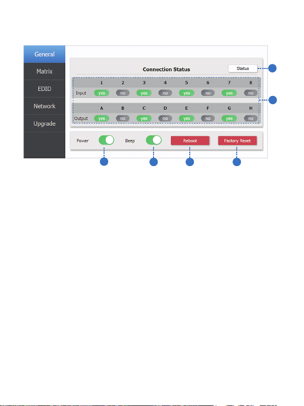
The Web GUI likes below:
2
1
34 5 6
①Click this button to check current the Matrix connection status.
②Display currently the Matrix input and output port status. The “yes”
have connected input or output source and “no” represent not connection.
③Power switch. The Matrix will work when open this switch. Otherwise, the
Matrix will standby.
④Beep switch. Open this switch, press the Matrix on-panel button will have
voice. Close this switch, it will mute.
⑤Click this button will reboot device.
⑥Click this button will set it to factory reset.
General page

10/12
①Select to the OUTPUT A input source. (Tab ① to other output port have
similar function.)
1
2
3
4
①Select EDID mode to input source, then click “Set” button.
②Copy EDID from output display to input source, then click “Set” button.
③Open EDID file to input source.
④Display the input source EDID mode status.
Matrix page
EDID page
11
11/12
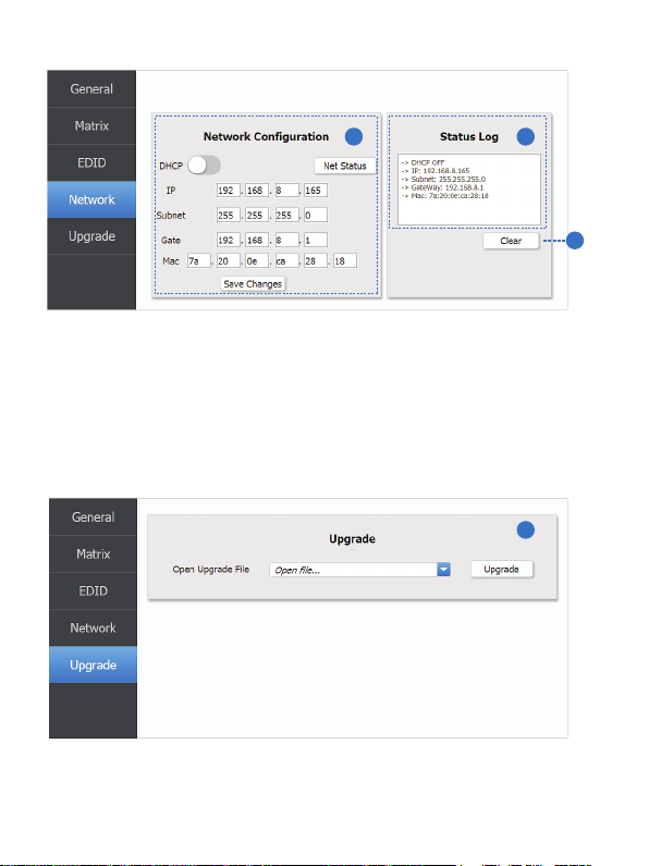
Network page
①Network Configuration
DHCP switch, Net Status button: Obtian the network configuration
information, including IP address, Subnet, Gate and Mac address, then
click “Save Changes” button.
②Status Log: Display the Net configuration information.
③Clear button: Click this button to clear the Status Log information.
21
3
Upgrade page
1
①Open upgrade file, then click the “Upgrade” button.

9. Application Example
12/12
AUDIO OUTPUT
OUTPUT
LAN
Table of contents
Other Network Devices Matrix Switcher manuals


