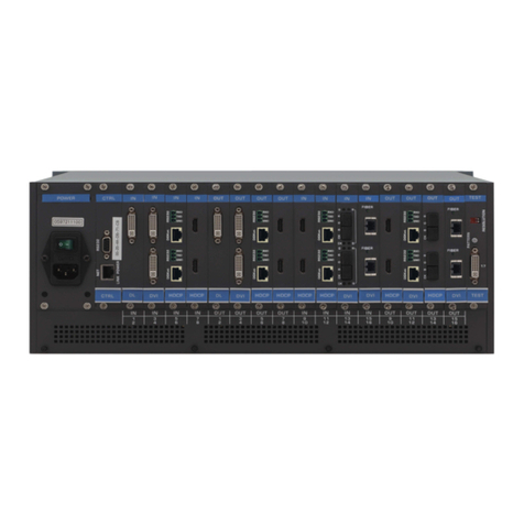
Network Devices ND-66-B70 User manual

3
ND-66-B70
6×6 HDMI 18Gbps
over HDBaseT™Matrix with Audio
Matrixing
VER 2.1

4
Thank you for purchasing this product
For optimum performance and safety, please read these instructions carefully before
connecting, operating or adjusting this product. Please keep this manual for future
reference.
Surge protection device recommended
This product contains sensitive electrical components that may be damaged by
electrical spikes, surges, electric shock, lightning strikes, etc. Use of surge protection
systems is highly recommended in order to protect and extend thelife of your
equipment.
Table of Contents
1. Introduction..................................................................................................... 5
2. Features........................................................................................................... 5
3. Package Contents ............................................................................................. 6
4. Specifications................................................................................................... 6
5. Operation Controls and Functions..................................................................... 7
6. PC control software and Web GUI................................................................... 13
7. Connection Diagram....................................................................................... 18

5
1. Introduction
The6x6 HDMI/HDBaseT matrix supports the transmissionof video(resolutions up to
4K2K@60Hz 4:4:4, HDCP 2.2, HDMI2.0) and multi-channeldigital audio from 6 HDMI
sources to 4 HDBaseT outputs and2 independentHDMI2.0 outputs. HDBaseT
outputs allow transmissionvia a single CAT5e/6/7 cable up to 230 feet/70meters and
the independent HDMIoutputs support cable lengths of up to 33 feet/10 meters.
This matrix built-in an independent 18x12 digital audio matrix with volume/delay
tuning and also supports highresolution digital audio formats such as LPCM
7.1CH,Dolby TrueHD,Dolby Digital Plus, Dolby Atmos and DTS-HD Master Audioas
well as 3Dvideo content pass-through. The matrix can be easily controlled via the
front panel button, IR, RS-232, Telnet and Web GUI.
2. Features
HDMI 2.0b (18Gbps), HDCP 2.2 and DVI compliant
Routes 6 HDMI sources to 6 displays including4 HDBaseT outputs and2
independent or mirrored HDMI outputs
Supports resolutions up to 4K@60 (YUV 4:4:4) on all HDMI ports
Supports automatic 4K@60 (YUV 4:4:4) to 4K@60 (YUV 4:2:0) conversion for all
HDBaseT outputs
4K/2K & 4K UHD signals can be transmitted up to 130 feet/40meters and 1080P
up to 230 feet/70 meters viaCAT5e/6/7
Supports pass-through of HD audio formats: LPCM 2/5.1/7.1CH,Dolby Digital
2/5.1CH, Dolby Digital Plus, Dolby TrueHD, DolbyAtmos, DTS-HD Master Audio
and DTS X
Built-in independent audio matrix with Volume, Mute, and Audio delay
adjustment for lip-sync (LPCM only)
HDR10, Dolby Vision, ARC, CEC and smart EDID management supported
24V POC on all HDBaseT ports
Control is via on-panel Button, IR, RS-232, Telnet and Web GUI
1U rack mounted design with aluminum front panel housing

6
3. Package Contents
1 x 6x6 Matrix Unit
4 x 70M HDBaseT Receivers
7 x Wideband IR Blaster cables
8 x Wideband IR Receiver cables
1 x RS-232 male to female cable
1 x AC power cable
1x Remote Controller
1 x User Manual
4. Specifications
Technical
HDMI Compliance
HDMI 2.0b
HDCP Compliance
HDCP 2.2 and HDCP 1.4
Video Bandwidth
Up to 18 Gbps
Video Resolutions
up to 4K2K@50/60Hz(YUV4:4:4),4K2K@30Hz,1080P@120Hz,
and 1080P 3D@60Hz
Color Space
RGB, YCbCr 4:4:4, YCbCr 4:2:2
Color Depth
10-bit, 12-bit
HDMI Audio Formats
(Pass-through)
LPCM 2/5.1/7.1CH, Dolby Digital, DTS 5.1, Dolby Digital+, Dolby
TrueHD, DTS-HD Master Audio, Dolby Atmos, DTS:X
Audio Formats
(Optical/Coaxial In)
LPCM 2/5.1/7.1CH, Dolby Digital, DTS 5.1, Dolby Digital+
Audio Formats
(Analog/Coaxial Out)
LPCM 2CH up to 192KHz sample rate
L/R Audio Formats
Analog Stereo 2CH
Infrared Frequency
20KHz - 60KHz
ESD Protection
Human body model —±8kV (air-gap discharge) & ±4kV (contact
discharge)
Connections
Inputs
6x HDMI Type A [19-pin female]
2x L/R Audio In [3.5mm Stereo Mini-jack]
2x Optical Audio In [S/PDIF]
2x Coaxial Audio In[S/PDIF]
8x IR In [3.5mm Stereo Mini-jack]
4x RS-232 [3pin Phoenix Jack]
1x TCP/IP[RJ45]

7
Outputs
2x HDMI Type A [19-pin female]
4x HDBaseT Out [RJ45]
6x L/R Audio Out [3.5mm Stereo Mini-jack]
6x Optical Out [S/PDIF]
7x IR Out[3.5mm Stereo Mini-jack]
Mechanical
Housing
Metal Enclosure
Color
Black
Dimensions
483 mm [W] x 303 mm [D] x 44.5 mm [H]
Weight
2110g
Power Supply
Input: AC100 - 240V 50/60Hz
Power Consumption
60W(Max)
Operation
Temperature
32 - 104°F / 0 - 40°C
Storage temperature
-4 - 140°F / -20 - 60°C
Relative Humidity
20 - 90% RH (no condensation)
5. Operation Controls and Functions
5.1 Front Panel
1. OLED Display: Displays the information of each input and output status, EDID
management and the matrix’s IP address.
2. IR Receiver Window: Receive IR signal.
3. Left/Right /Up/Down/Menu Buttons: After system power up, the OLED default
displays the map of the input and output, then you can operate the following
functions by the combination of these five buttons, included five Setup

8
Menu:Select EDID、PTP Set、Save Preset、Recall Preset、View IP and Set up the
map of input and output and Inquire each input's EDID status.
a. Select EDID: On the initial OLED display you can press “Menu”button to
enter Setup Menu page. You can press the “Up”and “Down”buttons into
select EDID mode page, the EDID table as showed in the below table, you
can press “Right”buttons into the EDID table and press "Up" or "Down"
buttons to select your chosen EDID, then you press "Right" button into
which selected inputs page and press "Up" or "Down" to select which
inputs copied the chosen EDID , pressing the “Menu”or "Right" button to
confirm this operation finally. If success the screen will go back to initial
OLED display.
The EDID table:
1
720p,Stereo Audio 2.0
2
1080p,Stereo Audio 2.0
3
1080p,Dolby/DTS 5.1
4
1080p,HD Audio 7.1
5
1080i,Stereo Audio 2.0
6
1080i,Dolby/DTS 5.1
7
1080i,HD Audio 7.1
8
3D,Stereo Audio 2.0
9
3D,Dolby/DTS 5.1
10
3D,HD Audio 7.1
11
4K2K30_444,Stereo Audio 2.0
12
4K2K30_444,Dolby/DTS 5.1
13
4K2K30_444,HD Audio 7.1
14
4K2K60_420,Stereo Audio 2.0
15
4K2K60_420,Dolby/DTS 5.1
16
4K2K60_420,HD Audio 7.1
17
4K2K60_444,Stereo Audio 2.0
18
4K2K60_444,Dolby/DTS 5.1
19
4K2K60_444,HD Audio 7.1
20
Copy EDID from HDMI output A
21
Copy EDID from HDMI output B
22
Copy EDID from HDMI output C
23
Copy EDID from HDMI output D
24
Copy EDID from HDMI output E
25
Copy EDID from HDMI output F
b. PTP Set: On the initial OLED display you can press “Menu”button to enter

9
Setup Menu page. You can press the "Up" or "Down" into the PTP Set
page. and press the "Right" to confirm this operation.
If success the screen will go back to PTP Set page, you can press "Left"
button to go back the initial OLED display.
c. Save Preset: On the initial OLED display you can press “Menu”button to
enter Setup Menu page. You can press the "Up" or "Down" buttons into
the Save Preset page, and press the "Right" button into the Save Preset.
There are five groups(Save to #1 or #5),you can press "Up" or "Down"
buttons to select which group you want to save all current settings on it.
Pressing the "Right" button to confirm this operation finally, If successful
the screen will go back to Save Preset page, you can press "Left" button to
go back the initial OLED display.
d. Recall Preset: On the initial OLED display you can press “Menu” button to
enter Setup Menu page. You can press the "Up" or "Down" buttons into
the Recall Preset page. and press the "Right" button into the ReCall Preset.
There are five groups (ReCall #1 or #5), you can press "Up" or "Down"
buttons to select which group you want to Recall all save settings from it.
Pressing the "Right" button to confirm this operation finally. If success the
screen will go back to Recall Preset page, you can press "Left" button to
go back the initial OLED display.
e. View IP: On the initial OLED display you can press “Menu” button to enter
Setup Menu page. You can press the "Up" or "Down" buttons into the
View IP page. Pressing the "Right" button to confirm this operation finally.
If success the screen will show the matrix IP address. You can press "Left"
button to go back the initial OLED display.
f. Selecting Input/output: On the initial OLED display you can press the
“Left”and “Right” buttons to select the output then press the “Up”and
“Down”buttons to select the input port, then press the “Menu”button to
confirm this operation.
g. EDID Status: On the initial OLED display you can press the “Up”and
“Down”button to check each input’s EDID setting, pressing the “Menu”
button go back to the initial OLED display.
4. Power Button: This button allows users to power on or standby the matrix.
5.Bi-Colors LED: The LED indicates the matrix status, Red color indicates the matrix
in standby mode and Green color indicates the matrix under normal working.

10
5.2 Rear Panel
1. HDMI In: Connect to HDMI source devices such as Blu-ray DVD or PS4.
2. 2 HDMI and 4 HDBaseT Out: 2 HDMI out connect to HDMI display devices and
4 HDBaseT connect to the HDBaseT receivers.
3.This is a two-way transmission port. The label C/D/E/F is corresponding to
HDBaseT C/D/E/F port. When the port connects another device, you can control
the device through PC from RS-232 port on the receiving end. When the port
connects PC, you can control far-end device through PC when the device
connects the RS-232 port on the receiving end.
4. LAN and RS-232 Control Port:
LAN port is for the TCP/IP control; connect to an active Ethernet link with an
RJ45 terminated cable.
RS-232 port connects to a PC or control system with DB9 cable for the
transmission of RS-232 commands.
The two ports also can be used for upgrading the matrix firmware.
5. AC Power Input: Connect to AC power supply.
6. IR EXT: If the unit is installed in a closed area out of infrared line of sight, IR EXT
port at the rear of unit can extend the matrix control IR by an external IR receiver
cable.
7. IR Input: Receiving the remote control signal andsending it to Receiver side.
8. IR Output: Sending the remote control signal from Receiver side.
9. Audio Input: Including two 3.5mm analog audio, two coaxial audio and two
optical audio inputs.
10. Audio Output: Six channels audio output ports, each channel has one 3.5mm
analog and one mirrored coaxial audio output.
11. GND Shielding: Connect to environment GND for better GND Shielding.

11
5.3 HDBaseT Receiver Panel
1. POWER LED: The LED will illuminate after the receiver is powered on.
2. DC 24V: In the matrix system, the jack doesn’t be used because of the power
from matrix POC output.
3. HDBaseT IN: Connect to the matrix HDBaseT output port.
4. HDMI OUT: Connect to the display device such as TV or projector.
5. IR IN: Connect to an IR receiver cable and the IR signal transmits through the
HDBaseT receiver to HDBaseT transmitter.
6. IR OUT: Connect to an IR Blaster cable and the IR signal transmits from matrix IR
In.
7. RS-232: Connect to PC or third-party RS-232 controller to control the matrix or
output from matrix’s RX-232 C/D/E/F port.
8. SERVICE: This port is used to upgrade the firmware of receiver device.
5.4 Matrix Remote Controller Introduction
Below introduces the matrix remote controller:
1. Power button
Click it the matrix will enter the standby or normal work mode.
2. Video Input Selection button
3. Video Output Selection button
How to use the video selection button?
Firstly, press the output A/B/C/D/E/F or ALL port
Then press the input 1/2/3/4/5 or 6 port.
For example if you want output C port to input 3, click output “C”
button, thenClick input “3”button to complete operation.
5.5 IR Pin Definition

12
IR Receiver and Blaster pin’s definition as below:
5.6 IR and RS-232 Instructions
The above connection diagram shows the IR and RS-232 connections:
1. IR Connection:
A. The IR INPUT / OUTPUT (1/2/3/4/5/6) of the matrix is associated with the IR
OUTPUT / INPUT of each HDBaseT receiver , and form the IR matrix port together.
The logic of the IR matrix follows the video map of the matrix at the same time.
For example: if video HDMI IN1 is selected to HDBaseT Out C, the matrix's IR
INPUT1 signal can be output from Receiver's IR out, and Receiver's IR IN can be
output from the matrix's IR output1,this Receiver is connected with the HDBaseT
OutC.
B. IR EXT: This port is used for controlling the matrix self.
C. IR ALL IN: This port is used for all HDBaseT Receiver IR out
It means that IR ALL IN port signal can be output from all HDBaseT
receiver's IR out

13
D. IR ALL OUT: This port is used for all HDBaseT Receiver IR in
It means that all HDBaseT receiver's IR in signal can be output from the
matrix's this port.
2. RS-232 Connection:
The matrix RS-232 (C/D/E/F) port is corresponding to each HDBaseT receiver’s
RS-232 port.
For example: The matrix C port's RS232 only Be transmitted in both directions
from HDBaseT Out C port receiver's RS-232 port.
5.7 Audio Matrix Instructions
This matrix incorporates an independent audio matrix with18 audio inputs
(including 6 HDMI de-embedding audio, 6 external audio sources and 6 ARC
audio), and 12 audio outputs (including 6 HDMI embedding audio to the
HDBaseT and HDMI outputs, 6 direct audio breakouts A-F).
In addition, Volume, Mute, Delay for Lip-Sync correction are available on all direct
audio outputs (PCM 2.0 audio only).
Audio sample rate supports up to 192 kHz.
Audio Volume is adjustable from 0dB to-50dB.
Delay value is adjustable from 0 to 2000ms.
Note: If you select the ARC audio as audio matrix input source, it doesn’t support
Volume/Mute/Delay adjustment and just pass-through without any audio
processing.
6. PC control software and Web GUI
6.1 PC control software user guide
The matrix can link with the PC control software by UART or TCP/IP mode:
1. UART mode
You need select the “COM Control Mode”in PC control software and the right
COM port of your PC or laptop, then click the connection button.

14
UART
mode
2. TCP/IP mode
a. The matrix default DHCP is enabling, after powering up 3 minutes if network
router doesn’t assign an IP address to the matrix, it will use an IP address
(192.168.1.100) as default IP.
b. The matrix and the PC on the same network IP segment with network router
and the matrix work on the DHCP status. You need search IP and click the
connect button.
c. Configure the IP address manually, you can set others IP address and be
sure your PC is the same IP segment with Matrix. You can connect the matrix via
PC host software.

15
TCP/IP mode
6.2 Web GUI
Before accessing matrix Web GUI, you should know current matrix IP address, you
can get it from the front OLED panel “Menu”->“View IP”page. Then you should set
the IP address of your PC or laptop or mobile device is within the same IP address
segment with the matrix. After above, you can enter the matrix IP address in the web
browser to access Web GUI.
Google Chrome, IE and Firefox browser are supported.
Web GUI each page as below:

16

17

18
7. Connection Diagram
Table of contents
Other Network Devices Matrix Switcher manuals

