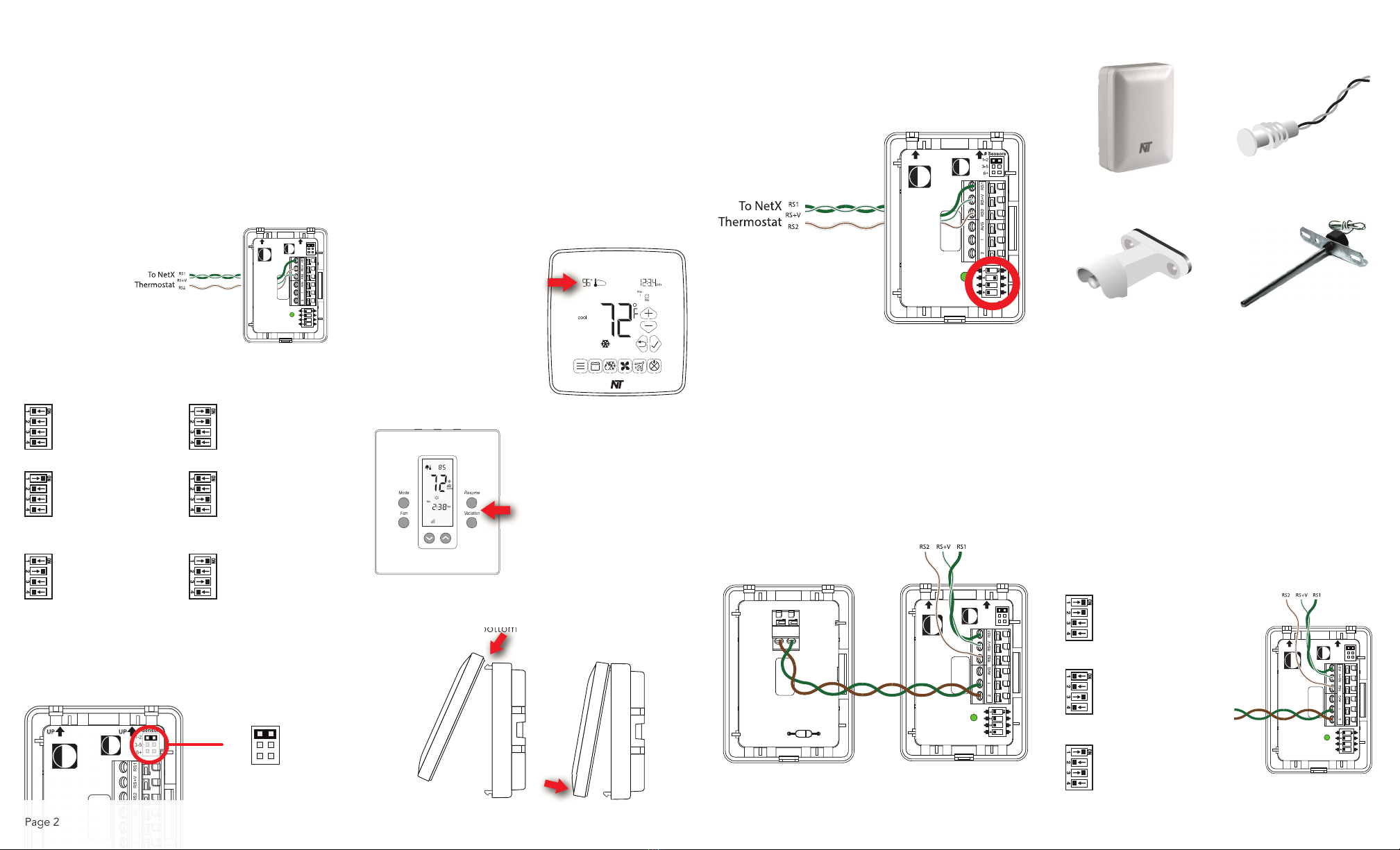
MULTIPLE INDOOR SENSOR
CONFIGURATION
You can connect up to six (6) NT-URS sensors to provide
INDOOR temperature averaging in a large area or several
zones being controlled by the same system. Maximum
distance for all sensors is 300 ft. (90m). Follow the instructions
and diagrams to connect the additional INDOOR sensors.
ANOTE:: Only ONE (1) NT-URS sensor congured as an
INDOOR sensor can be added in this manner. Additional
INDOOR sensors may be added by using the AVG terminals.
1. Wire the rst sensor using the single sensor instructions.
CCAUTION: Make sure there is no power to the sensors
by removing the thermostat from its backplate.
2. Connect wires to each additional sensor in the following
manner.
X-SERIES UP32/US32
3. Set #SENSORS jumper to 1-2 for ALL additional sensors
used for averaging.
4. Reinstall the thermostat faceplate on to its backplate. Check
proper operation by watching the LED blink pattern as
outlined in the LED Status section. Repeat for each sensor.
ONE (1) YEAR LIMITED WARRANTY
Network Thermostat™ warrants to the original purchaser that
this product will be free from defects in workmanship and
materials for a period of ve years from the date of purchase
with proof of purchase.
Warranty Limitations
This warranty begins on the date of purchase.
Warranty is Void if:
●The date code or serial number is defaced or removed.
●The product has a defect or damage due to product
alteration, connection to an improper electrical supply,
shipping and handling, accident, re, ood, lightning or other
conditions beyond the control of the manufacturer.
●The product is not installed according to the manufacturers
instructions and specications.
Owner’s Responsibility
●Provide proof of purchase.
●Provide normal care and maintenance.
●Pay for freight, labor and travel.
●Return any defective product.
●In no event shall the manufacturer be liable for incidental or
consequential damages.
This warranty gives you specic legal rights and you may have
others which vary by state and/or province. For example, some
states and/or provinces do not allow the exclusion or limitation of
incidental or consequential damages, so this exclusion may not
apply to you. The manufacturer’s continuing commitment to quality
products may require a change in specications without notice.
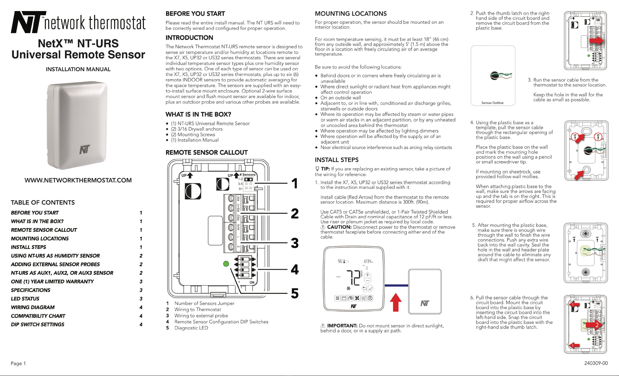
SPECIFICATIONS
Rated Voltage:
20V to 30VAC, 24VAC nominal
Internal Temp Sensor Range:
+28°F to 119°F in 1° steps (-2°C to 48°C in 1° steps)
External Temp Sensor Range:
Outdoor: -54°F to +119°F (-48°C to +48°C);
Auxiliary Temp Sensor Range:
AUX1, AUX2, AUX3: -40°F to +200°F (-40°C to +93°C)
Internal Humidity Sensor Range:
5% to 95% Relative Humidity, Non-condensing
Measurement Accuracy:
Temperature: ± 1.0°F (±0.5°C);
Humidity: 0-90%RH (±3%) ; 20-80% RH (±2%)
Terminations:
RS1 - Data, RS+V – Power, RS2 – Return, 1 & 2 – External Temp
Sensor Leads, 1-2, 3-5, 6+ Sensors
Dimensions:
2.1”H x 2.85”W x 1.0”D (53mm x 73mm x 25.4mm)
Approved Cable Types:
CAT5 or CAT5e unshielded, or 1-Pair Twisted Shielded Cable
with Drain and nominal capacitance of 12pF/ft or less. Use riser
or plenum jacket as required by local code.
Maximum 300ft Total Sensor Cable Length per Thermostat
LED STATUS
The NT-URS includes a Diagnostic LED that can help you
troubleshoot your installation and sensor operation.
LED Off:
LED OFF indicates no power to the NT-URS or thermostat.
Check wiring of your sensor and the thermostat for problems.
Fix as necessary.
LED On Solid During Power-Up:
On power-up the LED will turn on solid until the NT-URS
successfully communicates with the thermostat. If the
connection is successful, the LED will blink according to its
conguration. If the remains on, there is a communication
problem. Check wiring and x as necessary.
LED On Solid After Power Up:
If the NT-URS loses connection with the thermostat for 60
seconds, the LED will turn on solid. Check the wiring and x as
necessary. Cycle power cycle power and recheck the LED
status.
LED Slow Blink (Onboard Sensor Operation):
If the NT-URS is congured to use its internal sensor
(temperature or humidity) the LED will blink each time the
thermostat requests data. This occurs approximately every 16-
20 seconds.
LED Double Blink (Onboard Sensor Averaging):
If the NT-URS is congured to INDOOR temperature and an
additional sensor is connected to the AVG connection, the LED
will blink twice each time the thermostat requests data. This
occurs approximately every 16-20 seconds.
LED Triple Blink (External Probe Operation)
If the NT-URS is congured to use an external probe
connected to the 2-screwless terminals, the LED will blink three
times the thermostat requests data. This occurs approximately
every 16-20 seconds.
LED Fast Continuous Blink (Lost External Probe)
If the NT-URS is congured to use an external probe and the
NT-URS loses communication with the probe, the LED will
continually blink fast. Check wiring and external probe and x
as necessary.
ANOTE: In this condition, the NT-URS will stop reporting until
the communication with the external probe is xed.
Page 3
OFF ON
# Sensors
1-2
3-5
6+
UP UP
OFF ON
# Sensors
1-2
3-5
6+
UP UP
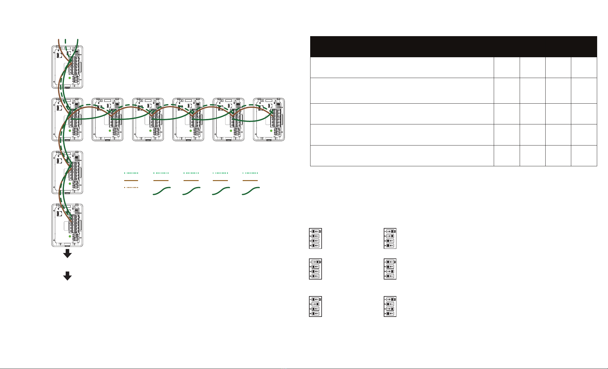
NT-URS
Additional NT-URS Sensors
Set as Indoor Sensor for
Temperature Averaging
NT-URS
First NT-URS in chain
Set as Indoor Sensor
OFF ON
# Sensors
1-2
3-5
6+
UP UP
NT-URS
First NT-URS in chain
Set as Indoor Sensor
Wiring To
Next Sensor
Up to 4
additional NT-
URS Sensors
can be added
to this chain.
X-SERIES UP32/US32
ANOTE: See
Page 2 Step 10 for
proper settings
ANOTE: Always
set additional
sensors to 1-2