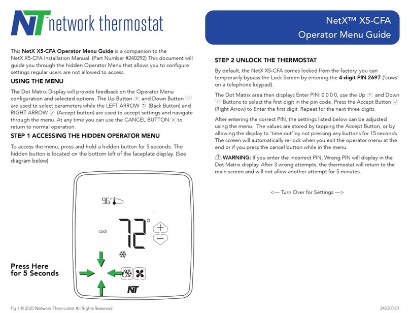
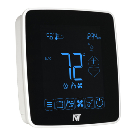
BUTTON PRESS COMBINATIONS
Single Press
• MODE Changes from HEAT to COOL to AUTO
to OFF.
• FAN Sets the fan ON (continuous), or AUTO
(operates with the equipment), or CIRC
(recirculation).
• RESUME Cancels Temporary or Vacation overrides
and resumes normal operating schedule.
• VACATION Starts the Vacation (or extended) override.
• UP Increments the blinking numerical or icon
segments of the display.
• DOWN Decrements the blinking numerical or icon
segments of the display.
Multi-Press
• UP & DOWN Toggles between °F and °C.
• RESUME & Displays Outdoor Temperature
VACATION (if thermostat is connected to the internet)
for 30 seconds.
Press and Hold (for 12 seconds)
• MODE Resets the thermostat to factory defaults.
Press and hold the MODE button for 12
seconds to evoke the number of resets.
Press the MODE button a second time to
reset the defaults.
NOTE: All schedules will be reset.
• FAN Enters thermostat sensor de-calibration
mode. Allows a temperature offset of up
to +/-3°F. To remove the de-calibration,
press and hold the MODE button.
• MODE & FAN Enter Address Mode (change thermostat
communications address)
• RESUME & Allows for adjustment of High and Low
MODE balance points when displaying outdoor
temperature (hold for 5 seconds).
NOTE: The thermostat must be connected
to the internet for this feature to be available.
• FAN & VACATION Sets desired time period for a temporary
temperature override.
FEATURES AND SETTINGS, con’d
Override Timer Conguration
You will be able to adjust the length of a temporary override
condition from 15 minutes to 8 hours, in 15 minute increments.
To display/set the Override time, press and hold the FAN and
VACATION buttons for 12 seconds, then press the UP or DOWN
button. Future ‘overrides’ to the schedule will hold the setpoint
for the desired time and then return to the pre-programmed
schedule.
COVER LOCK
You also may lock the cover down to prevent unauthorized ac-
cess to the thermostat by adding the clear plastic lock (included
in the installation bag). To install, remove the thermostat from
the backplate and place the clear plastic lock in the backplate
as shown below. Replace the thermostat and close the cover.
The cover now is locked. To open, simply use a screwdriver
to carefully push the lock back, allowing the cover to open. To
remove the lock, open the cover, remove the thermostat from the
backplate, and then remove the lock.
REPLACING THE THERMOSTAT ON
THE BACKPLATE
1. Position the thermostat on the hinged tabs located at the top
of the backplate.
2. Gently swing the thermostat down and press on the bottom
center edge until it snaps in place.
FEATURES AND SETTINGS
LED #1 (GREEN): Filter Indicator
The green (left) LED may be used together with the FILTER icon
to indicate the HVAC system’s air lter(s) need to be changed.
LED #2 (YELLOW): Service Indicator
The yellow (right) LED may be used together with the WRENCH
icon to indicate there is a problem with the HVAC system.
LED #3 (RED): Auxiliary/Emergency Heat Indicator
The red (center) LED will illuminate when the thermostat has
engaged a heat pump system into either auxiliary heat mode or
emergency heat mode.
Note: The green, yellow and red LEDs may also be used to
indicate Off-Peak, Mid-Peak and On-Peak time of use (TOU)
energy rate pricing plans as dened by your electric utility
provider. This feature is only available when the thermostat is
connected via communications to your utility company’s network.
While NetworkThermostat has included these LEDs to be
accessible by utility companies, use of this feature may require
upgraded rmware or communications hardware, yet to be
dened by NetworkThermostat or your utility company.
Add-On (Dual-Fuel) Heat Pump Control
If needed, the thermostat will perform the function of a fossil
fuel kit. When in this mode, the thermostat will turn off the
compressor with a call for AUX heat. When Switch 1 and
Switch 5 are in the ON position, the thermostat allows the
compressor and the AUX heat to be on simultaneously.
Random Restart
After a power failure, the thermostat will delay the heating/
cooling equipment start-up by 8-40 seconds. When multiple
Net/X™ RP32-NX thermostats are used, this minimizes the ‘in
rush’ current (electric power usage) as it reduces the number of
HVAC units that will be turned on simultaneously.
High & Low Balance Point Conguration
If the thermostat is being used as a Heat Pump thermostat
(Dip Switch #1 in the ON position), and outdoor temperature
information is available by using an Internet connection, the
thermostat can be congured to disable the use of auxiliary
heat during warmer weather and to lock out the compressor
during colder weather.
To display/set the High and Low balance points:
1. Press RESUME and VACATION together to show the outdoor
temperature.
2. Press and hold the MODE and RESUME buttons for 5 seconds
to evoke the High and Low balance point temperatures.
The display will indicate the high or low balance point and the
selected temperature. Press the UP or DOWN button to adjust
the balance point temperature. Pressing the MODE button again
will toggle to the alternate balance point.
NOTE: Refer to the heat pump equipment manual for
temperature cut-offs on the equipment.
DESCRIPTION OF THE DIP SWITCH FUNCTIONS
DIP Switch 1: GE/HP Operation
Place DIP Switch 1 in the OFF position for Gas/Electric furnace
operation.
Place DIP Switch 1 in the ON position for Heat Pump operation.
DIP Switch 2: Adaptive Setpoint Recovery
Place DIP Switch 2 in the OFF position for Adaptive Setpoint
Recovery operation. When this is enabled, the thermostat will
anticipate when to turn on the heating or cooling system prior to
the start of a schedule in order to achieve the desired setpoint
temperature by the beginning of the schedule.
DIP Switch 3: 2 Minute or 4 Minute Minimum On/Off Times
When DIP Switch 3 is in the ON position, the minimum ON/OFF
time is 2 minutes. The system will operate for a minimum of 2
minutes or 4 minutes, and allow equipment recovery for 2 or 4
minutes before turning on again. This is also known as short
cycle protection.
DIP Switch 4: Unlocked/Locked Keypad
When DIP Switch 4 is in the ON position, all buttons are disabled
with the exception of the UP, DOWN and MODE button. Users
will be restricted to either a +/-3°F or +/-5°F range from the
scheduled setpoints as dened by Dip Switch #7 for the
programmed override time. Users will still be able to cycle
between HEAT and COOL.
DIP Switch 5: Plenum Fan Switch /Add-On Heat Pump
DIP Switch 5 is used to determine when the fan needs to be
turned on.
Place DIP Switch 5 to OFF and DIP Switch 1 to OFF to have the
fan turn on immediately when there is a call for heat. (Required
with electric heat.)
Place DIP Switch 5 to ON and DIP Switch 1 to OFF to have the
plenum switch operate the fan.
Place DIP Switch 5 to OFF and DIP Switch 1 to ON for normal
heat pump operation.
Place DIP Switch 5 to ON and DIP Switch 1 to ON for Add-On
(Dual-Fuel) Heat Pump operation.
DIP Switch 6 :
Multi-Stage System Operation Place DIP Switch 6 to OFF
position for single-stage applications.
(single-stage compressors and heaters)
Place DIP Switch 6 to ON position for multi-stage applications.
(two-stage compressors and heaters)
DIP Switch 7 : Temporary Override Adjustment Range
Place DIP Switch 7 to OFF to limit temporary adjustments to
+/- 3°F.
Place DIP Switch 7 to ON limit temporary adjustments to +/- 5°F.
DIP Switch 8 : Not Used
Keep OFF.
6 7 85
