manuals.online logo
Brands
  1. Home
  2. •
  3. Brands
  4. •
  5. Seitron
  6. •
  7. Thermostat
  8. •
  9. Seitron TA S05M User manual

Seitron TA S05M User manual

TAS05M0001AN 031288 051218
Fig. 5
6
5
4
1
Fig. 1
1
2
Fig. 3
Fig. 2
3
3
Fig. 4
Cable Aperture
38 mm
10 mm
43 mm
82 mm
60 mm
41 mm
82 mm
8
TERMOSTATO ELETTRONICO AMBIENTE PER SISTEMI DI RISCALDAMENTO
CON MODALITA' DI 'RIDUZIONE NOTTURNA'
ELECTRONIC ROOM THERMOSTAT FOR HEATING SYSTEM WITH NIGHT SET BACK MODE
THERMOSTAT ELECTRONI UE D'AMBIANCE POUR SYSTÈMES DE CHAUFFAGE AVEC
RÉDUCTION NOCTURNE
TERMOSTATO ELECTRÓNICO DE AMBIENTE PARA SISTEMAS DE CALEFACCIÓN CON MODALIDAD
DE REDUCCIÓN NOCTURNA
Fig. 6
7
9 8
0
+4
-4
Fig. 7 Fig. 8
NIGHT SET BACK (NSB):
Contatto orologio per attivazione modalità 'Riduzione notturna' / Time switch contacts for operation of 'night setback' mode / Contact
horologe pour activation de la 'rédiction nocturne' / Contacto reloj para activación modalidad 'Reducción nocturna'.
TAS05M0001AN 029756 150218
2
- ITALIANO -
sensore interno. Nel caso in cui l'installazione preveda un montaggio
con sonda a distanza, è necessario rimuovere il connettore jumper JP1
(9 di Fig. 6 , e collegare una sonda di tipo NTC da 4700 Ohm a 25°C
con adeguato valore per il parametro beta ai morsetti 7 e 8. In caso di
dubbio sul tipo di sonda da collegare si prega di consultare il
costruttore.
IMPOSTAZIONE OFFSET SU SENSORE INTERNO / SONDA
REMOTA
Tramite un trimmer interno (
8
di Fig. 6 , posto vicino al trimmer per la
regolazione della temperatura ambiente, è possibile impostare il valore
dell’offset sul sensore interno o sonda remota nel range -4°C .. +4°C.
- Se il trimmer e completamente ruotato in senso antiorario (minimo
l’offset è impostato -4°C.
- Se il trimmer e completamente ruotato in senso orario (massimo
l’offset è impostato a +4°C.
- Se il trimmer e ruotato nel mezzo (posizione centrale l’offset è
impostato a 0°C.
Il termostato esce dalla fabbrica con il trimmer impostato su 0°C.
CARATTERISTICHE TECNICHE
Alimentazione: TA S05M: 230V~ 50Hz
TA S052: 24V~ 50Hz
Potenza assorbita:
TA S05M: 5,3VA
TA S052: 0,3VA
Campo di regolazione: 6°C .. 30°C
Riduzione notturna: 2°C .. 7°C regolabile (Default 4,5°C
Offset sensore interno /
sonda remota: -4°C .. +4°C (Default 0°C
Differenziale: 0,5°C
Tipo di sensore interno: NTC 4,7kΩ@ 25°C
Sonda remota: NTC 4,7kΩ@ 25°C
(opzionale
Portata contatti: 5(1 A 250V~ SPDT
Grado di protezione: IP 30
Tipo di azione: 1
Grado di inquinamento: 2
Categoria di sovratensione: II
Classe di protezione contro
le scosse elettriche: II
Tensione impulsiva nominale: 2500V
Indice di tracking (PTI : 175
Numero di cicli manuali:: 50.000
Numero di cicli automatici: 100.000
Classe del software: n.a.
Tensione prove EMC: 230V~
Corrente prove EMC: 25mA
Tolleranza distanza esclusione
modo guasto ‘corto’: ±0,15mm
Temperatura prova sfera: 75°C
Temp. di funzionamento: 0°C .. 40°C
Temp. di stoccaggio: -10°C .. +50°C
Umidità relativa: 20% .. 80% RH (non condensante
Contenitore: Materiale: ABS V0 autoestinguente
Colore: Bianco segnale (RAL9003
Dimensioni: 85x85x31 mm (L x A x P
CLASSIFICAZIONE SECONDO REGOLAMENTO 2013.811.CE
Classe: I
Contributo all’efficienza energetica: 1%
GARANZIA
Nell'ottica di un continuo sviluppo dei propri prodotti, il costruttore si
riserva il diritto di apportare modifiche a dati tecnici e prestazioni senza
preavviso. Il consumatore è garantito contro i difetti di conformità del
prodotto secondo la Direttiva Europea 1999/44/c nonché il documento
sulla politica di garanzia del costruttore.
Su richiesta è disponibile presso il venditore il testo completo della
garanzia.
GENERALITA'
Questo dispositivo è un termostato elettronico per sistemi di
riscaldamento particolarmente adatto alla regolazione, in maniera precisa
ed affidabile, della temperatura di ambienti, case, scuole, sale, officine
etc. La rilevazione della temperatura ambiente può essere effettuata dal
sensore interno oppure da una sonda remota (opzionale .
FUNZIONAMENTO
Quando la temperatura ambiente rilevata è inferiore a quella impostata
con la manopola, il termostato attiva il relè e contemporaneamente si
accende il LED rosso posto sul frontale.
IMPOSTAZIONE TEMPERATURA AMBIENTE
Tramite la manopola di regolazione è possibile impostare la temperatura
attorno a cui verrà effettuato il controllo della temperatura, come indicato
al paragrafo precedente, nel range 6°C .. 30°C.
BLOCCO MANOPOLA
E' possibile ridurre il campo entro cui ruota la manopola eseguendo i
seguenti passi:
1. Sollevare la manopola facendo leva con un cacciavite nell'apposito
invito (2.
2. Prelevare i cavalieri meccanici (4 parcheggiati a lato della sede
manopola e posizionarli (5 come nell'esempio di Fig. 5. In questo
modo il campo di rotazione (6 è ridotto come nell'arco indicato.
INSTALLAZIONE
a
ATTENZIONE
-
Per una corretta regolazione della temperatura ambiente si
consiglia di installare il termostato a circa 1,5 metri dal
pavimento, lontano da fonti di calore, correnti d'aria o da pareti
particolarmente fredde (ponti termici). Se si usa una sonda a
distanza la nota va applicata alla sonda e non al termostato.
-
Per i collegamenti della sonda usare cavi di sezione minima 1,5
mm² e di lunghezza massima di 25 m. Non passare i cavi della
sonda nelle canaline della rete.
-
Collegare l'apparecchio alla rete di alimentazione tramite un
interruttore onnipolare conforme alle norme vigenti e con
distanza di apertura dei contatti di almeno 3 mm in ciascun polo.
- L'installazione ed il collegamento elettrico del termostato
devono essere eseguiti da personale qualificato ed in
conformità alle leggi vigenti.
- Prima di effettuare qualsiasi collegamento accertarsi che
l’alimentazione di rete sia scollegata.
Per installare il dispositivo eseguire le seguenti operazioni:
1. Sollevare la manopola facendo leva con un cacciavite nell’apposito
invito (2.
2. Rimuovere la calotta plastica spostando verso l'interno, con l'aiuto
di un utensile, i due dentini plastici (3 posti sul fianco destro.
3. Fissare la base del termostato alla parete tramite le due sedi per viti
con interasse 60 mm (Fig. 4 .
4. Eseguire i collegamenti elettrici, facendo passare i fili tramite
l’apertura rettangolare (8, seguendo lo schema di collegamento di
Fig. 7 o Fig. 8.
5. Richiudere il termostato posizionando la calotta attentamente in
modo che il LED entri nel foro apposito e successivamente
esercitando una pressione che faccia scattare i quattro dentini
plastici di fissaggio. Quindi reinserire la manopola.
RIDUZIONE NOTTURNA (Night Set Back)
Al morsetto 6 (Fig. 7 e 8 è possibile collegare un contatto esterno che
consente di attivare la modalità di 'Riduzione Notturna' (Night Set
Back . Questa modalità consente di ridurre la temperatura impostata
con la manopola di un valore pari a quello impostato sul trimmer interno
(7) di Fig. 6, nel range 2°C .. 7°C. Il termostato esce dalla fabbrica con
il trimmer impostato su 4,5°C.
SELEZIONE SONDA INTERNA / ESTERNA
Il termostato esce dalla fabbrica predisposto per il funzionamento con
TAS05M0001AN 031288 051218
OVERVIEW
This device is an electronic room thermostat for heating systems
suitable for reliable and accurate temperature regulation in commercial
and industrial premises as well as for home installation.
The room temperature can be sensed by the internal sensor or a remote
sensor (optional .
OPERATION
When the measured room temperature is below the value set on the dial
the thermostat turns the relay on and, at the same time, turns the red
LED on.
SETTING THE ROOM TEMPERATURE
The user can set the room temperature by moving the dial to any
desired temperature, as explained in the former paragraph, between
6°C and 30°C.
KNOB ROTATION LIMITATION
It is possible to limit the rotation range for the set-point knob by
following these steps:
1. Remove the knob by tilting it, eventually with the help of a
screwdriver placed in the slot (2.
2. Pick up the plastic pins (4 parked at one side of the knob area and
set them (5 as in the example of Fig. 5. In this example the rotation
range (6 is reduced as in the shown angle.
INSTALLATION
a
WARNING
- To adjust properly room temperature, install the thermostat
about 1.5m from floor level, far from heat sources, airstreams
or particularly cold walls (thermal bridges). When the remote
sensor is used in conjunction with the thermostat, then this
note is to be applied to the remote sensor itself.
- For remote version all wirings must be made using wires with
1,5 mm² minimum cross section and no longer than 25 m. Do
not use same duct for signal wires and mains.
-
The appliance must be wired to the electric mains through a
switch capable of disconnecting all poles in compliance with the
current safety standards and with a contact separation of at least
3 mm in all poles.
- Installation and electrical wirings of this appliance must be
made by qualified technicians and in compliance with the
current standards.
- Before wiring the appliance be sure to turn the mains power
off.
For installation the thermostat follow these steps:
1. Remove the knob by tilting it, eventually with the help of a
screwdriver placed in the slot.
2. Remove plastic cover by moving to the inner side, through the use of
a tool (Fig. 2 , the two plastic teeth (3 located on the left side
(Fig. 3 of the thermostat.
3. Fix the thermostat base plate to the wall through the two screw
holes with distance between axes of 60 mm.
4. Make the electrical connections, routing the wires through the
rectangular opening (8 and following to the diagram of Fig. 7 or 8.
5. Close the thermostat by carefully positioning the cover so that the
LED matches the relevant hole and then by slightly pressing the
cover in order to make the four plastic teeth snapping.
Then insert the knob.
NIGHT SET BACK
In order to select the 'Night Set Back' feature an external dry contact
can be connected to terminal 6 (Fig. 7 and 8 . This mode results in
reducing the temperature set with the external dial by an amount set
with the internal trimmer (7 in Fig. 6, in the range 2°C .. 7°C.
The thermostat leaves the factory with the trimmer set on 4.5°C.
SELECTION INTERNAL/EXTERNAL SENSOR
The thermostat leaves the factory configured by default for operation
- ENGLISH -
3
with the internal temperature sensor. If it is planned to install a remote
sensor, remove the jumper connector JP1 (9 of Fig. 6 and connect an
NTC type sensor (4700 ohm@ 25°C with a suitable beta value to
terminals 7 and 8. In case of doubt as to the type of sensor to connect,
please consult the manufacturer.
OFFSET SETTING ON THE INTERNAL SENSOR / REMOTE
SENSOR
Using an internal trimmer (8 of Fig. 6 , placed near the trimmer for the
regulation of the room temperature, it is possible to set the offset value
on the internal sensor or the remote sensor, within the range
-4°C .. +4°C.
- If the trimmer is completely rotated in counter clock wise direction
(minimum the offset is set to -4°C.
- If the trimmer is completely rotated in clockwise direction (maximum
the offset is set to +4°C.
- If the trimmer is rotated centrally (middle position the offset is set to
0°C.
The thermostat comes by default with the trimmer set on 0°C.
TECHNICAL FEATURES
Power supply: TA S05M: 230V~ 50Hz
TA S052: 24V~ 50Hz
Power absorption: TA S05M: 5,3VA
TA S052: 0,3VA
Regulation range: 6°C .. 30°C
Night set back: 2°C .. 7°C adjustable
(Default 4,5°C
Offset internal sensor /
remote sensor: -4°C .. +4°C (Default 0°C
Differential: 0,5°C
Internal sensor type: NTC 4,7kΩ@ 25°C
Remote sensor optional: NTC 4,7kΩ@ 25°C
(optional
Contact rating: 5(1 A 250V~ SPDT
Protection grade: IP 30
Type of action: 1
Pollution degree: 2
Overvoltage category: II
Class of protection against
electric shock: II
Rated impulse voltage: 2500V
Tracking Index (PTI : 175
Number of manual cycles: 50.000
Number of automatic cycles: 100.000
Software class: n.a.
EMC test voltage: 230V~
EMC test current: 25mA
Distances tolerances fault
mode ‘short’ exclusion: ±0,15mm
Ball pressure test temperature:
75°C
Operating temperature: 0°C .. 40°C
Storage temperature: -10°C .. +50°C
Humidity limits: 20% .. 80% RH (non condensing
Case: Material: ABS self extinguishing V0
Color: Signal white (RAL 9003
Size: 85x85x31 mm (W x H x D
CLASSIFICATION UNDER REG. 2013.811.EC
Class: I
Contribution to energy efficiency: 1%
WARRANTY
The manufacturer is committed to the continual development of its
products and hence reserves the right to change technical
specifications and performance features without notice. Consumers are
provided with a warranty against product non-conformity in accordance
with European Directive 1999/44/c and the manufacturer’s guarantee
policy. The complete text of the warranty is available on request from
the seller.
TAS05M0001AN 029756 150218
GÉNÉRALITÉ
Ce thermostat électronique pour systèmes de chauffage est
particulièrement adapté au réglage de la température de manière
précise et fiable pour les habitations, salles, écoles, ateliers, etc. Le
relevé de la température ambiante peut être effectué soit par le capteur
intérieur, soit par la sonde à distance (en option .
FONCTIONNEMENT
Quand la température relevée est inférieure à celle qui est programmée
avec le bouton de réglage, le thermostat active le relais et un LED rouge
positionné frontalement s'allume.
PROGRAMMATION TEMPÉRATURE
Grâce au bouton de réglage, il est possible de régler la température dont
le contrôle sera effectué comme indiqué ci-dessus, champ de réglage
6°C .. 30°C.
BLOCAGE DU BOUTON
Il est possible de réduire le champs de réglage du bouton:
1. Soulever le bouton en faisant levier avec un tourne-vi
(
2
.
2. Extraire les cavaliers mécaniques (4 situés sur les côtés du bouton
et les positionner (5 comme dans l'exemple de la Fig. 5.
De cette façon, le champs de rotation (6 est réduit dans l'arc choisi.
INSTALLATION
a
ATTENTION
-
Pour un réglage correct de la température, il est conseillé
d'installer le thermostat à environ 1,5 m du sol, éloigné des sources
de chaleur, courants d'air ou des parois particulièrement froides
(ponts thermiques). Si une sonde à distance est utilisée, cette note
est appliquée à la sonde et non au thermostat.
- Dans les versions avec sonde à distance, éviter de les placer en
contact avec les câbles de puissance. Utiliser un câble isolé
bipolaire avec mèche libre de section minimum 1,5 mm² (max.
25 m).
- Brancher l'appareil au réseau d'alimentation avec un
interrupteur omnipolaire conforme aux normes en vigueur et
avec une distance d'ouverture des contacts d'au moins 3 mm à
chacun des pôles.
- L'installation et le branchement électrique du dispositif doivent
être réalisés par un personnel qualifié et en conformité aux lois
en vigueur.
- Avant d'effectuer tout type de branchement, s'assurer que le
réseau électrique soit hors tension.
Pour installer le thermostat effectuer les opérations suivantes:
1. Soulever le bouton en faisant levier dans l’emplacement prévu (2.
2. Retirer la calotte de plastique en appuyant vers l'intérieur sur les
deux petites dents de plastique (3 situées sur les côtés.
3. Fixer la base du thermostat au mur au moyen des deux trous prévus
pour les vis avec un interaxe 60 mm (Fig. 4 .
4.
Effectuer les raccordements électriques en faisant passer les fils à
travers l’ouverture rectangulaire (
8
, selon le schéma de la Fig. 7 ou 8.
5. Refermer le thermostat en repositionnant soigneusement la calotte
de sorte que le LED se positionne sur l'emplacement prévu à cet
effet et effectuer une légère pression afin d'enclencher les 4 petites
dents de fixation. Enfin repositionner le bouton de réglage.
RÉDUCTION NOCTURNE (Night Set Back)
Pour activer la modalité 'Réduction Nocturne' (Night Set Back , il faut
connecter un contact externe à la borne 6 (Fig. 7 ou 8 . Cette fonction
permet de réduire la température fixée manuellement par le bouton
d’une valeur égale à celle qui est programmée sur le trimmer interne (7
de Fig. 6, sur une plage entre 2°C .. 7°C. Le thermostat sort de l’usine
avec le trimmer programmé sur 4,5°C.
SÉLECTION SONDE INTÉRIEURE / EXTÉRIEURE
Le thermostat sort d’usine prêt à fonctionner avec une sonde intérieure.
Si l’installation prévoit un montage avec sonde à distance, extraire le
connecteur à bretelle JP1 (9 di Fig. 6 puis brancher une sonde NTC de
- FRANÇAIS -
4
4700 ohm à 25 °C, avec une valeur adéquate pour le paramètre bêta,
aux bornes 7 et 8. En cas de doutes sur le type de sonde à brancher,
consulter le fabricant.
RÉGLAGE OFFSET SUR CAPTEUR INTERNE / SONDE À
DISTANCE
Par un potentiomètre interne (8 de Fig. 6 , placé près du potentiomètre
pour le réglage de la température ambiante, on peut régler la valeur de
l’offset sur le capteur interne ou sur la sonde à distance dans la plage
de -4°C .. +4°C.
- Si le potentiomètre est à l’extrémité de sa rotation anti-horaire
(minimum l’offset est réglé sur -4°C.
- Si le potentiomètre est à l’extrémité de sa rotation horaire (maximum
l’offset est réglé sur +4°C.
- Si le potentiomètre est au milieu (position centrale l’offset est réglé
sur 0°C.
Le thermostat sort d’usine avec le potentiomètre réglé sur 0°C.
CARACTÉRISTI UES TECHNI UES
Alimentation : TA S05M : 230V~ 50Hz
TA S052 : 24V~ 50Hz
Puissance électrique :
TA S05M : 5,3VA
TA S052 : 0,3VA
Champs de réglage : 6°C .. 30°C
Réduction nocturne : 2°C .. 7°C réglable
(Default 4,5°C
Offset capteur interne /
Sonde á distance:
-4°C .. +4°C (Default 0°C
Différentiel : 0,5°C
Type de capteur intérieur : NTC 4k7 ohm @ 25°C
Sonde à distance : NTC 4k7 ohm @ 25°C
(en option
Portée des contacts : 5(1 A 250V~ SPDT
Degré de protection : IP 30
Type d’action : 1
Degré de pollution : 2
Catégorie de surtension : II
Classe de protection contre les
chocs électriques : II
Tension impulsive nominale : 2500V
Indice de localisation (PTI : 175
Nombre de cycles manuel : 50.000
Nombre de cycles automatiques :
100.000
Classe du software : n.a.
Tension essai EMC : 230V~
Courant essai EMC : 25mA
Tolérance distance d’exclusion
mode panne ‘court-circuit’ : ±0,15mm
Température essai sphère : 75°C
Temp. de fonctionnement : 0°C .. 40°C
Temp. de stockage: -10°C .. +50°C
Limite d'humidité : 20% .. 80% RH
(sans condensation
Boîtier: Matière: ABS V0 auto extinctible
Couleur: Blanc de sécurité (RAL9003
Dimensions : 85x85x31 mm (LxHxP
CLASSEMENT SELON LE RÈGLEMENT 2013.811.EC
Classe : I
Contribution à l’efficacité énergétique : 1%
GARANTIE
Dans l’optique d’un développement continu de ses produits, le
constructeur se réserve le droit d’apporter sans préavis, des
modifications aux données techniques et aux prestations de ces
derniers. Selon la Directive Européenne 1999/44/c et le document qui
reporte la politique de garantie du constructeur, le consommateur est
protégé contre les défauts de conformité du produit. Le texte complet
de la garantie est disponible auprès du vendeur sur demande.
TAS05M0001AN 031288 051218
GENERALIDADES
Este termostato electrónico para sistemas de calefacción es apropiado
para la regulación precisa y confiable de la temperatura de ambientes
como, casas, escuelas, salas, oficinas etc. El control de la temperatura
ambiente puede ser efectuado por el sensor interno o bien por la sonda
remota (opcional .
FUNCIONAMIENTO
Cuando la temperatura ambiente detectada es inferior a la ajustada con
el mando giratorio, el termostato activa el relé y contemporaneamente
se enciende el LED rojo ubicado en el frontal.
AJUSTE TEMPERATURA AMBIENTE
Mediante el mando de regulación es posible establecer una temperatura
en torno a la cual será efectuado el control de la temperatura, como
indica el párrafo anterior, en el rango 6°C .. 30°C.
BLO UEO MANDO
Es posible reducir el campo en el que rueda el mando siguiendo los
siguientes pasos:
1. Levantar el mando haciendo palanca con un destornillador en la
embocadura (2.
2. Retire los interruptores de corredera mecánicos (4 ubicados al
costado del asiento del mando y posiciónelos (5 como en el ejemplo
de la Fig. 5.
De este modo el campo de rotación (6 estará reducido como en el
arco indicado.
INSTALACIÓN
a
ATENCIÓN
-
Para una correcta regulación de la temperatura ambiente se
aconseja instalar el termostato a más o menos 1,5 del piso, lejos de
fuentes de calor, corrientes de aire o de paredes particularmente
frías (peuntes térmicos). Si se usa una sonda a distancia la nota
anterior se aplica a la sonda y no al termostato.
- Para la conexión de la sonda usar cables de sección minima 1,5
mm² y longitud max. de 25 m. No pasar los cables de la sonda
en las canaletas de la red eléctrica.
-
Conectar el aparato a la red de alimentación mediante un
interruptor omnipolar conforme a las leyes vigentes y con una
distancia de apertura de los contactos de al menos 3 mm en cada
uno de los polos.
- La instalación y la conexión eléctrica deben ser realizadas por
personas cualificadas y en conformidad con las leyes vigentes.
- Antes de efectuar cualquier conexión asegúrarse que la red
eléctrica esté desconectada.
Para instalar el termostato realizar las siguientes operaciones:
1. Levantar el mando giratorio haciendo palanca con un destornillador
en la embocadura pertinente (2.
2. Sacar la tapa desplazando los dos dientes de plástico (3 ubicados
en el costado derecho del aparato ayudándose con un utensilio.
3. Fijar la base del termostato en la pared mediante con 2
tornillos a una distancia entre ellos de 60 mm (Fig. 4 .
4. Realizar las conexiones eléctricas, haciendo pasar los cables a
través de la apertura rectangular (8, siguiendo el esquema de la
Fig. 7 o 8.
5. Cerrar el termostato posicionando la tapa atentamente de modo que
el LED entre en el orificio y posteriormente ejercite una presión
hasta sentir el chasquido de los dientes de fijación.
REDUCCIÓN NOCTURNA (Night Set Back)
Al borne 6 (Fig. 7 o 8 es posible conectar un contacto externo que
permite activar la modalidad de 'Reducción Nocturna' (Night Set Back .
Esta modalidad permite de reducir la temperatura ajustada con el
mando giratorio de un valor par al ajustado en el trimmer interno (7) de
Fig. 6, en el rango 2°C .. 7°C. El termostato sale de fábrica con el
trimmer ajustado a 4,5°C.
SELECCIÓN SONDA INTERNA / EXTERNA
El termostato sale de fábrica predispuesto para el funcionamiento con
- ESPAŇOL -
5
sonda interna. Si la instalación prevé un montaje con sonda a distancia,
es necesario extraer el conector jumper JP1 (9 di Fig. 6 y conectar una
sonda de tipo NTC de 4700 ohm a 25°C con un adecuado valor para el
parámetro beta a los bornes 7 y 8. Si se tiene dudas respecto el tipo de
sonda que se debe conectar, se aconseja, consultar al constructor.
AJUSTE OFFSET EN SENSOR INTERNO/SONDA REMOTA
Mediante un trimmer interno (8 de Fig. 6 , ubicado cerca del trimmer
para la regulación de la temperatura ambiente, es posible ajustar el
valor del offset en el sensor interno o sonda remota en el rango -4°C ..
+4°C.
- Si el trimmer está completamente girado en el sentido anti-horario
(mínimo el offest está ajustado en -4°C.
- Si el trimmer está completamente girado en el sentido horario
(máximo el offset está ajustado en +4°C.
- Si el trimmer está girado en el medio (posición central el offset está
ajustado en 0°C.
El termostato sale de la fábrica con el trimmer ajustado en 0°C.
CARACTERÍSTICAS TÉCNICAS
Alimentación: TA S05M: 230V~ 50Hz
TA S052: 24V~ 50Hz
Absorción: TA S05M: 5,3VA
TA S052: 0,3VA
Campo de regulación: 6°C .. 30°C
Reducción nocturna: 2°C .. 7°C ajustable
(Default 4,5°C
Offset sensor interno /
sonda remota: -4°C .. +4°C (Default 0°C
Diferencial: 0,5°C
Tipo de sensor interno: NTC 4,7kΩ@ 25°C
Sonda remota: NTC 4,7kΩ@ 25°C
(opcional
Capacidad contactos: 5(1 A 250V~ SPDT
Grado de protección: IP 30
Tipo de acción: 1
Grado de contaminación: 2
Categoría de sobretensión: II
Clase de protección contra
descargas eléctricas: II
Tensión impulsiva nominal: 2500V
Índice de tracking (PTI : 175
Nombre de cycles manuels: 50.000
Número de ciclos automáticos:
100.000
Clase del software: n.a.
Tensión pruebas EMC: 230V~
Corriente pruebas EMC: 25mA
Tolerancia distancia exclusión modo mal
funcionamiento ‘cortocircuito’:
±0,15mm
Temperatura prueba esfera: 75°C
Temp. de funcionamiento: 0°C .. 40°C
Temp. de almacenamiento: -10°C .. +50°C
Límite de humedad: 20% .. 80% RH (no condensable
Caja: Material: ABS V0 autoextinguible
Color: Blanco señal (RAL 9003
Dimensiones: 85x85x31 mm (A x H x P
CLASIFICACIÓN SEGÚN EL REGLAMENTO 2013.811.EC
Calse: I
Contribución a la eficiencia energética: 1%
GARANTÍA
En la óptica de un continuo desarrollo de los propios productos, el
fabricante, se reserva el derecho de aportar modificaciones a los datos
técnicos y prestaciones sin previo aviso.
El consumidor está garantizado contra defectos de conformidad del
producto según la Directiva Europea 1999/44/c y con el documento
sobre la políitica del constructor.
A pedido del cliente se encuentra disponible en el negocio vendedor el
texto completo de la garantía.
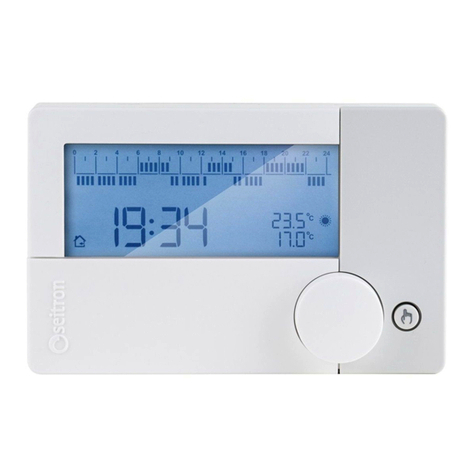
This manual suits for next models

1

Other Seitron Thermostat manuals

Seitron freetime evo User manual

Seitron

Seitron freetime evo User manual

Seitron FREETIME PLUS VIA RADIO User manual

Seitron

Seitron FREETIME PLUS VIA RADIO User manual

Seitron T RD02B User manual

Seitron

Seitron T RD02B User manual

Seitron T.HYGROS THW02B User manual

Seitron

Seitron T.HYGROS THW02B User manual

Seitron Wi-Time WiFi User manual

Seitron

Seitron Wi-Time WiFi User manual

Seitron wi-time User manual

Seitron

Seitron wi-time User manual

Seitron TAG02M User manual

Seitron

Seitron TAG02M User manual

Seitron wi-time User manual

Seitron

Seitron wi-time User manual

Seitron hygge home User manual

Seitron

Seitron hygge home User manual

Seitron TFA01M User manual

Seitron

Seitron TFA01M User manual

Seitron freetime evo User manual

Seitron

Seitron freetime evo User manual

Seitron DCPA80BC Quick guide

Seitron

Seitron DCPA80BC Quick guide

Seitron wi-time User manual

Seitron

Seitron wi-time User manual

Seitron freetime evo User manual

Seitron

Seitron freetime evo User manual

Seitron DTP F85 BC0 0SE User manual

Seitron

Seitron DTP F85 BC0 0SE User manual

Seitron hygge home User manual

Seitron

Seitron hygge home User manual

Seitron TA D01B User manual

Seitron

Seitron TA D01B User manual

Seitron TBM01M User manual

Seitron

Seitron TBM01M User manual

Seitron freetime evo User manual

Seitron

Seitron freetime evo User manual

Seitron TCD01B User manual

Seitron

Seitron TCD01B User manual

Seitron TA D02B User manual

Seitron

Seitron TA D02B User manual

Seitron T.HYGROS THW01B User manual

Seitron

Seitron T.HYGROS THW01B User manual

Seitron FREETIME PLUS User manual

Seitron

Seitron FREETIME PLUS User manual

Seitron i-10 User manual

Seitron

Seitron i-10 User manual

Popular Thermostat manuals by other brands

Comfort Stat BLU2810 owner's manual

Comfort Stat

Comfort Stat BLU2810 owner's manual

CORAB TSTPHA01, COR 5 owner's manual

CORAB

CORAB TSTPHA01, COR 5 owner's manual

Alarmcom ADC-T2000 product manual

Alarmcom

Alarmcom ADC-T2000 product manual

eControls Comfort365 C365T21WF user manual

eControls

eControls Comfort365 C365T21WF user manual

System air TControl POD Operation manual

System air

System air TControl POD Operation manual

Pro 1 IAQ T855S Operation manual

Pro 1 IAQ

Pro 1 IAQ T855S Operation manual

CTC Union ULTIMATE Series Installer manual

CTC Union

CTC Union ULTIMATE Series Installer manual

Johnson Controls T8680 Owner's manual and installation instructions

Johnson Controls

Johnson Controls T8680 Owner's manual and installation instructions

Server EZ-TOPPER 12B Series manual

Server

Server EZ-TOPPER 12B Series manual

Energate Pioneer Z100 Smart Thermostat OPERATING AND INSTALLATION Manual

Energate

Energate Pioneer Z100 Smart Thermostat OPERATING AND INSTALLATION Manual

BVF Heato9 user manual

BVF

BVF Heato9 user manual

HYSEN HY08AC manual

HYSEN

HYSEN HY08AC manual

Drayton RF700/22090 User instructions

Drayton

Drayton RF700/22090 User instructions

Carrier edge Performance TP PHP01 A Series owner's manual

Carrier

Carrier edge Performance TP PHP01 A Series owner's manual

Perel CTH406 user manual

Perel

Perel CTH406 user manual

Hive HAH2PMZ installation guide

Hive

Hive HAH2PMZ installation guide

Johnson Controls NXT-INT-01 installation guide

Johnson Controls

Johnson Controls NXT-INT-01 installation guide

Danfoss TP5000 si range User instructions

Danfoss

Danfoss TP5000 si range User instructions

manuals.online logo
manuals.online logoBrands
  • About & Mission
  • Contact us
  • Privacy Policy
  • Terms and Conditions

Copyright 2025 Manuals.Online. All Rights Reserved.