Networkfleet 5500 User manual

5500 Diagnostic Hardware (Light/Medium/Heavy Duty) | 5200 Non-Diagnostic Hardware (Universal)
www.networkeet.com | Customer Care: 866.227.7323 customercare@networkeet.com
Networkfleet 5000 Product Line
Installation Guide

Table of Contents
Getting Started
Registration form ...............................................................................................................................................3
5000 Product Line
Unit Overview....................................................................................................................................................4
Harness Options for the 5000 Product Line ...............................................................................................5-6
Installation Instructions
Light/Medium Duty OBD-II Harness Installation ....................................................................................7-9
Heavy Duty Harness Installation ..................................................................................................................10
Universal Harness Installation..................................................................................................................11-12
Verifying Successful Installation....................................................................................................................13
Creating Tamper Evidence.............................................................................................................................. 14
Completing Installation...................................................................................................................................15
Securing the Device .........................................................................................................................................16
Optional Accessories
Optional Window-Mount GPS Antenna Installation Instructions ........................................................... 17
Optional Sensor Installation Instructions ...............................................................................................18-20
Optional Garmin® Installation Instructions ................................................................................................ 21
Optional NMEA Feed Installation Instructions........................................................................................... 22
Verifying Successful Installation/LED Behavior....................................................................................23-24
Appendix
Troubleshooting Light Indicators .............................................................................................................25-26
Frequently Asked Questions .......................................................................................................................... 27
Contacting Networkeet.................................................................................................................Back Cover
2
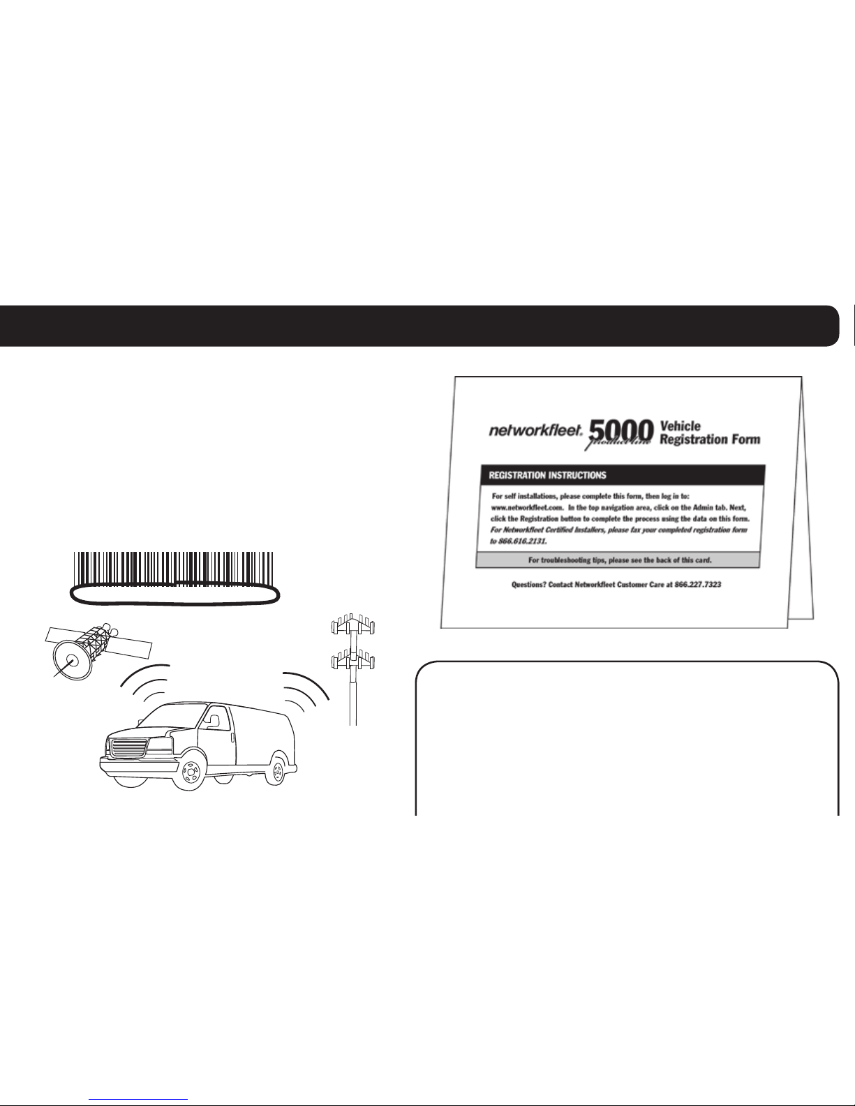
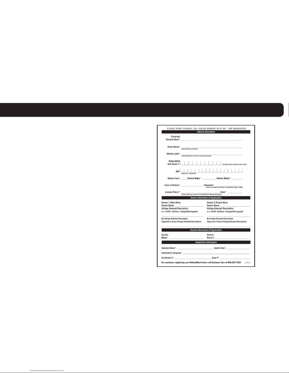
Registration Form
Fill out the enclosed registration form
before completing installation.
Record the following information:
•VehicleIdenticationNumber(VIN)
•LicensePlate•Year•Make
•Model•Unit’sSerialnumber(10digits)
5000915003
Installation Tip: Metal walls and tall buildings may
interfere with the reception from GPS satellites and
the cellular network. Perform installation when the
vehicleisinclearviewofthesky.Conductnal
installationvericationafterthevehiclehasbeen
running outside for 15 minutes.
3
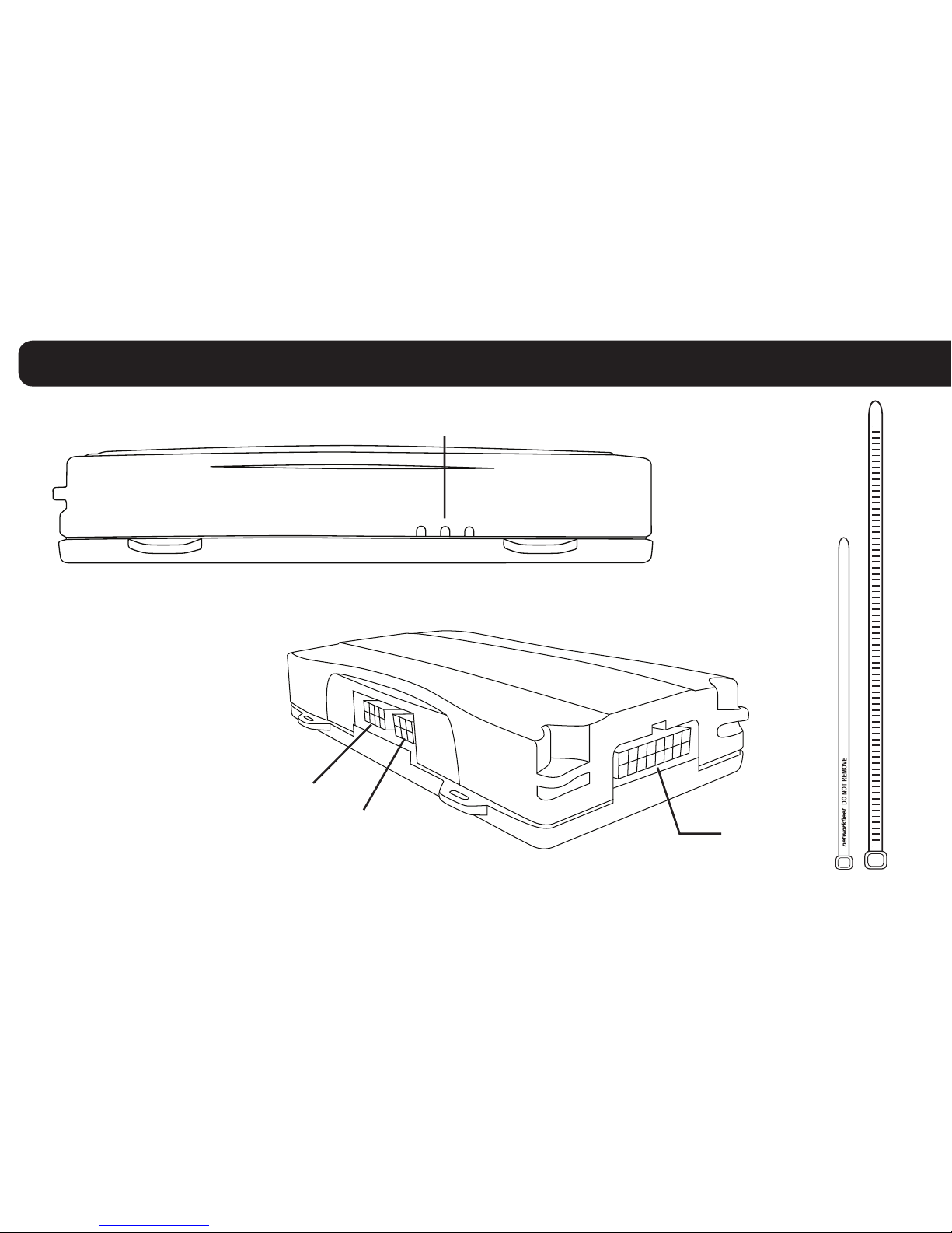
5000 Product Line Unit Overview
ZipTies(X4)
Data Port
Serial Port
LED Indicator Lights
Side of Unit
Sensor Port
Note: All 5500 and 5200 units
are shipped with a knock-out
panel covering the sensor/
serial ports. In order to access
those ports, you must use an
X-ACTOknifetosliceoff2of
the 3 tabs in order to remove
the knock-out panel.
4

Prior to installation, you must select
and order the appropriate harness for
your vehicle type. The Light/Medium
Duty OBD-II Harness and the Heavy
Duty Harnesses are compatible with
both the 5500 and 5200 hardware
devices. Please refer to the list below
to verify harness compatibility for
each of the 5000 series devices:
5500(DiagnosticCapableHardware)
• Light/MediumDutyOBD-IIHarness
• HeavyDutyHarnesses
(6-pin,9-pin,or9-pin“D”)
5200(Non-DiagnosticHardware)
• UniversalHarness
• Light/MediumDutyOBD-IIHarness
• HeavyDutyHarnesses
(6-pin,9-pin,or9-pin“D”)
Harness Options for the 5000 Product Line
HarnessAdaptersfortheLight/MediumDutyOBD-IIHarness(X8)
Core Connector for the
Light/Medium Duty
OBD-IIHarness(X1)
Bypass
Connector
OBD-II Replacement Connector
Harness
Connector
Harness
Connector
Light/Medium Duty OBD-II Harness Universal Harness (5200 Only)
5

Harness Options for the 5000 Product Line
There are 3 different
harness options for Heavy
Duty vehicle installations:
6-pin Harness, 9-pin Harness,
and9-pin“D”Harness.
6-pin Harness 9-pin Harness
Heavy Duty Harnesses
9-pin“D”Harness
6
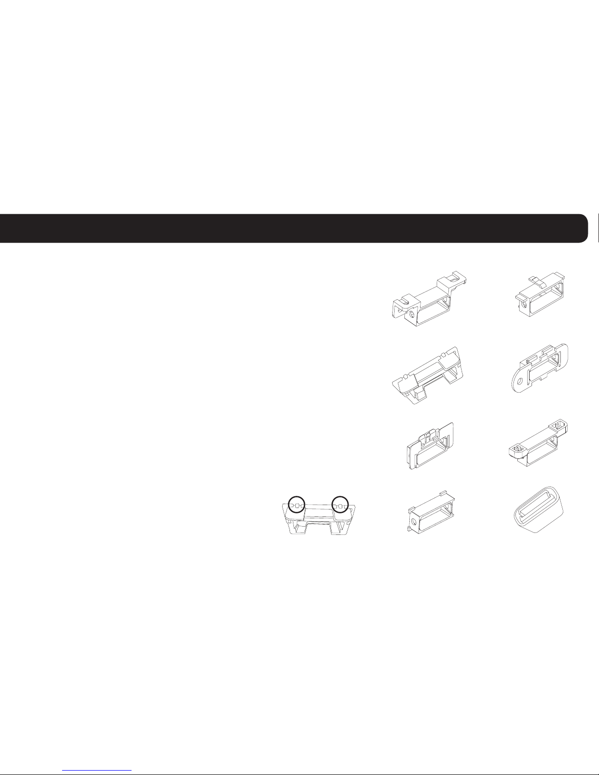
Select an Adapter that most resembles the shape of the
OBD-II port of the vehicle. Use these guidelines to match
anadaptertothevehicleitismostlikelytot(eachadapter
isstampedwithanumber).
Ford, GM (1), (6), or (8)
Honda, Lexus, Toyota, Chrysler (2)
Toyota*, Chrysler* (2a)
GM, Saturn (3)
Mercedes, BMW (4)
Porsche, Audi, Volkswagen (5)
Volvo (6)
Saab (7)
* For certain Toyota and Chrysler vehicles,
you may need to adjust the #2 adapter by
removing the clips on the top and bottom
of the adapter. To the right is an example
of the adjusted adapter labeled (2a).
(1)
(2)
(3)
(4)
(2a)
(5)
(6)
(7)
(8)
Light/Medium Duty OBD-II Harness Installation
Heavy Duty Harnesses
7

Core Connector Assembly
1. Snap the selected plastic adapter
to the back of the Core Connector.
2. Attach the Core Connector to the
OBD-II Replacement Connector.
Data Port Connection
1. Connect the Harness
Connector to the Data Port. Bypass
Connector
Networkeet Unit
Harness
Connector
Data Port
OBD-II Replacement
Connector
Light/Medium Duty OBD-II Harness Installation
Adapter
Core
Connector
8

Connecting to the OBD-II Port
1.Withthevehicle’sengineOFF,removethevehicle’sOBD-IIport.
•TheOBD-IIConnectormaybehiddenbehindahushpanel.
•Toremovetheconnector,youmayneedtoremovescrewsordepresstheclips.
2.ConnecttheBypassConnectortothevehicle’sOBD-IIportthatwas
previously removed.
3. Attach the Core Connector to the position where the original
OBD-II connector was installed. Secure it with the screws or
clipsremovedfromtheOBD-IIConnector’soriginal
position(ifapplicable).
Light/Medium Duty OBD-II Harness Installation
to vehicle
Networkeet Unit
Dashboard
Core Connector
Bypass Connector
Original OBD-II Port
9
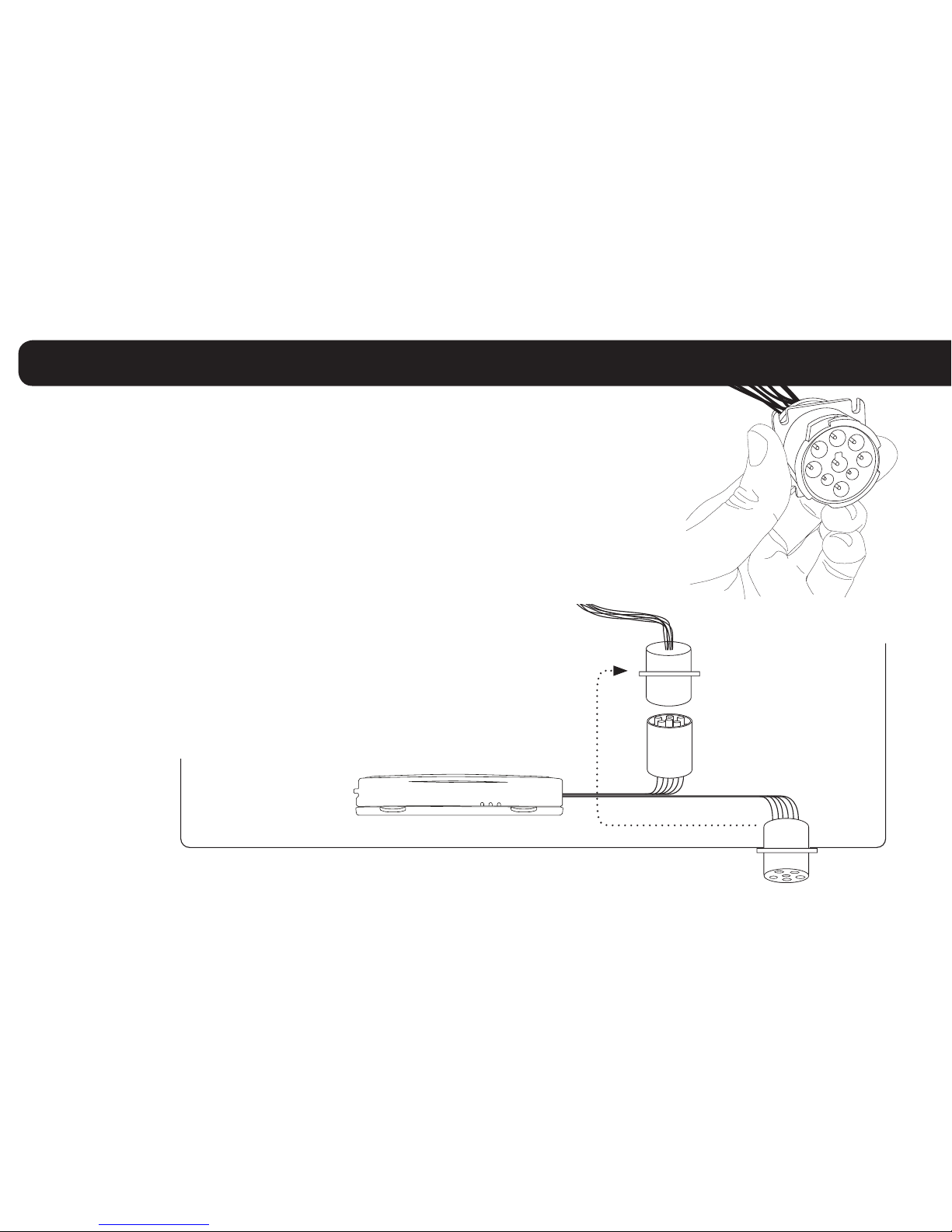
Heavy Duty Harness Installation
Connecting to the Diagnostic Link Connector (DLC) Port
1.Withthevehicle’sengineOFF,unscrewtheDLCportfromitspositionunder
the dashboard*. In most cases, the DLC port is located under the dashboard
on the left side of the steering wheel, facing toward the oorboard.
2. Plug the Bypass Connector of the harness into the DLC port that was
previously removed from the vehicle in step 1. For the 9-pin connector,
turn the rotating cap clockwise to lock into place.
3. Mount the Core Connector of the harness into the place
in which the DLC port originally resided.
*Note: DLC Port Connector may also be located near or
behind the driver seat.
to vehicle
Networkeet Unit
Dashboard
Core Connector
Bypass Connector
Original DLC Port
10

Connecting to Ground and Power
Black Wire - Ground
•Withthevehicle’sengineOFF,attachtheBlackWire
directlytoachassisgroundpointortoagroundline(chassisground)bysplicingdirectlytoa
groundleadorbyusingawiretap(recommended).
Red Wire - Continuous Power
•Withthevehicle’sengineOFF,usethevoltmetertolocatea12-voltBATTERYleadandattach
theRedWirebysplicingdirectlytotheleadorbyusingawiretap(recommended).Ifattaching
toafusedleadorusinganinlinefuse(notnecessary),verifythatitisatleast5amps.
•Becarefulnottoconfusea“RetainedAccessoryPower(RAP)”linewithatrue
ContinuousPowerline(12volt,alwaysONline).
•To determine a true Continuous Power source:
1)EnsuretheDriverDoorisOPEN
2)Selectawire
3)Withvehicle’sengineOFF,useavoltmetertomeasuretheDCvoltageonthewire.
It should show 12 VDC or higher.
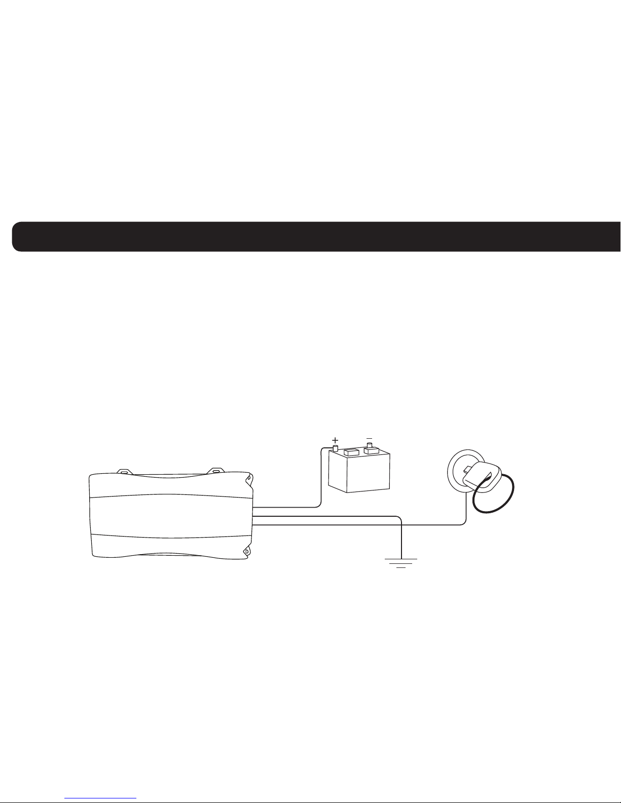
Universal Harness Installation
Note: Please ensure that the Driver
Door is OPEN during the ENTIRE
installation process.
11
Blue Wire - Switched Power
•Withthevehicle’sengineOFF,usethevoltmetertolocateanIGNITIONlinewithswitchedpowerand
attachtheBlueWiretothelinebysplicingdirectlytotheleadorbyusingawiretap(recommended).
•DoNOTuseaninlinefuseonthisline.
•DoNOTuseaccessoryPower.
•Todetermineaswitchedpowersource:
1)EnsuretheDriverDoorisOPEN
2)Selectawire
3)WithengineOFF,usevoltmetertomeasuretheDCvoltageonthewire.Itshouldshow0VDC.
4)Starttheengineandconrmthatthevoltageofthesamewireis13.1VDCorhigher
5)Turnthevehicle’sengineOFFandconrmthatthevoltageofthesamewireis0VDC
Networkeet Unit
ConstantPower(Battery) Switched Power
Red Wire
Blue Wire
Black Wire
Ground
Universal Harness Installation
12
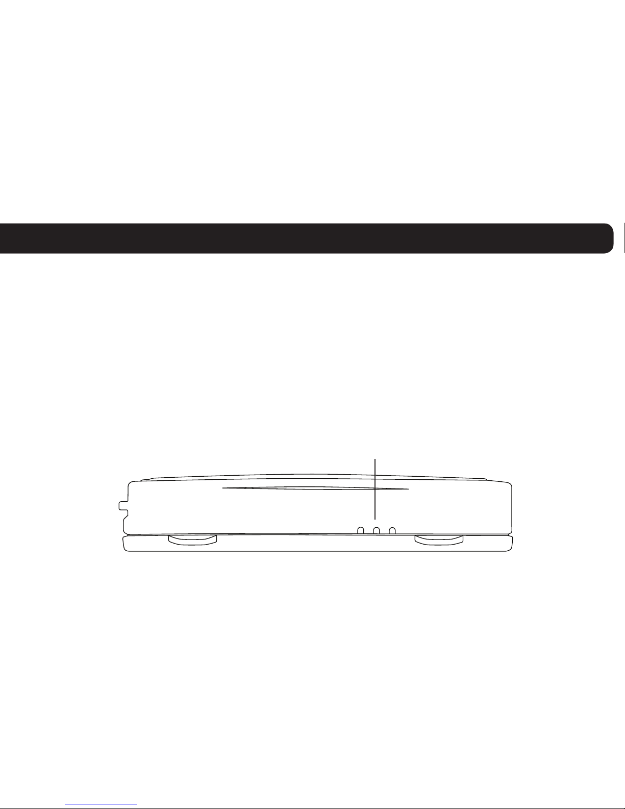
Verifying Successful Installation
1.Startthevehicle’sengine.Alllights(Red,Yellow,andGreen)onthedeviceshouldturnon
solidfor15secondsandthenbeginblinkingrapidly(twiceasecond).
2. The device is operating normally when the rapid blinking ceases and the Green and
Yellowlightsbegintoblinkinaslowpattern(ONfor5secondsandOFFfor1second).
The Red light pattern will continue to vary and should not be used to verify installation.
3. The vehicle must be idled or driven for at least 15 minutes to reach normal operating mode
and ensure activation is complete.
Side of Unit
LED Light Indicators
13

Once the vehicle harness is plugged in,
slide the Networkeet branded yellow zip
ties through the two slots provided on the
harness connector. Once the zip ties are
in place, tighten and remove the excess
plastic. If possible, position the zip ties so
thatthe“DONOTREMOVE”messageis
showing.
Creating Tamper Evidence
14
Before securing the device under
the dashboard, make sure that you
have recorded the VIN, hardware
serial number, and odometer reading
on the registration form. Also verify
that you have checked the light
indicators. After installation, provide
the registration form to the eet
manager for delivery to Networkeet
orifyouareaNetworkeetCertied
Installer, please fax to 866.616.2131 or
email to installs@networkeet.com.
Completing Installation 15

Securing the Device
Use zip ties to fasten the hardware securely to a
stable bracket or wire bundle under the dash.
IMPORTANT: The device must be installed high
in the dashboard area and secured with the top of
theunitfacingthesky(thesideoftheunitwiththe
Networkeetlogo).Alsoverifythatthedeviceis
not covered by metal and check that the green LED
isblinkinginaslowpattern,whichveriesthatthe
unitisgettingGPSdata(asexplainedonpage13).
To avoid damage from condensation,
ensure that the unit is not at the lowest
point of the installation and secure it
away from moving parts.
16

To Install
1.Unitsareshippedwithaknock-outpanelcoveringthesensor/serialports.First,useanX-ACTOknifetosliceoff2of
the 3 tabs in order to remove the knock-out panel.
2. Use enclosed alcohol preparation pad to clean the inside windshield where the antenna is to be placed. For proper
operation,theantennashouldbeplacedonat,clearglassonthedriver’ssideinteriorlowercornerofthewindshield.
Ensure that the antenna does not extend more than 4 ½ inches from the bottom of the interior windshield and is located
outside the area swept by the windshield wipers.
Do NOT place the antenna in the following areas - Behind stickers or decals already on the glass, on the shade band of
theglass,onacurvedareaoftheglass,onamoistordampareaoftheglass,oronanareathatwillobstructthedriver’sview
3. Connect the window-mount GPS antenna to the serial port on the side of the unit.
4. Run the cables up the door seam or up through the dashboard.
5. Remove the protective strip from the antenna to expose the adhesive.
6.CarefullyafxtheantennatotheglassthatwaspreppedinStep2.Pressthe
antennarmlytotheglasswhilebeingcarefulnottodamagetheantenna.
Note: The optional window-mount GPS antenna may be used simultaneously with either of the
Garmin cables or the NMEA cable. The NMEA and Garmin cables may not be used simultaneously.
Installation Tip: Please note that the ideal temperature range to
performtheinstallationisbetween70°Fto100°F(21°Cto38°C)
withaminimumsuggestedapplicationtemperatureof60°F(15°C).
Window-Mount
GPS Antenna
Windshield
4 ½ inches
max
Optional Window-Mount GPS Antenna Installation Instructions 17

The 5500 and 5200 devices include a sensor port for monitoring various voltage events
occurring within the vehicle such as: PTO engagement/disengagement, secondary engine
on/off, and door open/close.
Please review prior to performing sensor installation:
• Installershalluseonlyadigitalmulti-metertoverifythatlineVoltageandAmperagearewithinthe
product tolerances.
• Installershalluse24gauge(minimum)wiresforinstallation.
• Electricalconnectorsmustbeusedwhenattachingsensorwires.
• Voltagetestingshouldalwaysbeperformedwithavehicledooropentoavoidretainedaccessory
power issues.
The 5500/5200 comes equipped with two sensor inputs. Each sensor will be associated with a pair of
inputwires.Onepairofwires(Purple,Black)willbeassociatedwithSensor1andtheotherpairofwires
(Blue,Black)willbeassociatedwithSensor2.
Use the Black wire of each pair to make a secure vehicle ground connection. Then, connect the other wire
(BlueorPurple)ofeachpairtothedesiredsignaltobemonitored.
Optional Sensor Installation Instructions
18

Ifonlyonewirepair(sensorinput)istobeused,theotherpairmustbetwistedtogetherandinsulatedvia
heat shrink or some other secure means to prevent contact with any vehicle structures and to ensure it does
not interfere with any moving parts in the vehicle.
Thesignaltobemonitoredshouldhavetwovoltagestates:Onewherethereisnovoltage(i.e.zerovolts
whenreferencedtoground)andanotherthatfallsintherange+5to+24or-5to-24volts.Thesignalbeing
monitored should be capable of supplying 3 mA when a voltage is present. It is important that the voltage
signalbetestedtoensureitiscontinuouslyprovidingthenecessaryvoltageandcurrentwheninthe“on”
or“active”position.
The following table shows how the signals are interpreted.
Note:Ifyou’rereplacingapreviouslyinstalled3500/SSEMwithsensorinput(s)witha5000seriesunit,
you must reinstall the sensor inputs using the Sensor Input Harness available for the 5000 series unit.
The SSEM sensor harness is NOT compatible with the 5000 series units.
Optional Sensor Installation Instructions (cont.)
WireA(Black) GroundorreferenceforwireB
WireB(BlueorPurple) Off(-3V<x<+3V)
On(-24V<x<-5Vor+5V<x<+24V)
Undened(-5V<x<-3Vor+3V<x<+5V)
19

To Install
1. Unitsareshippedwithaknock-outpanelcoveringthesensor/serialports.First,useanX-ACTOknifetosliceoff2
of the 3 tabs in order to remove the knock-out panel.
2. Connect the Sensor Input Harness to the Sensor Port on the 5500 or 5200 device.
3. VerifyinstallationbycheckingtheLEDbehaviorofthedevice(seepage23)andcallCustomerCareat866.227.7323
and select Option 5.
4. Before secvvuring the device under the dashboard, make sure you have recorded the appropriate information on the
Sensor Installation Card included with the Sensor Input Harness. Once all information is recorded, follow the
instructions detailed on the card to update your eet on www.networkeet.com.
Optional Sensor Installation Instructions (cont.)
Data Port
Serial Port
Sensor Port
Sensor Input
Harness
(Blue&Purple)
Note: The optional window-mount GPS antenna may be used simultaneously with either of the Garmin cables or the
NMEA cable. The NMEA and Garmin cables may not be used simultaneously.
20
This manual suits for next models
1
Table of contents


