Netzer VLX-60 User manual
User Manual
Absolute Position Rotary Electric Encoder™|VLX-60
VLX-60 | July 2018 | Ver. 02
Corporate Headquarters
Netzer Precision Motion Sensors Ltd. | Misgav Industrial Park, P.O. Box 1359 | D.N. Misgav, 2017400 Israel
Tel : +972 4 999 0420 | global-info@netzerprecision.com | www.netzerprecision.com
Moving. Precisely. With You.
1
USER MANUAL
All specifications are subject to change without notice
User Manual
Absolute Position Rotary Electric Encoder™|VLX-60
VLX-60 | July 2018 | Ver. 02
Corporate Headquarters
Netzer Precision Motion Sensors Ltd. | Misgav Industrial Park, P.O. Box 1359 | D.N. Misgav, 2017400 Israel
Tel : +972 4 999 0420 | global-info@netzerprecision.com | www.netzerprecision.com
Moving. Precisely. With You.
2
Contents |Preface |Safety |Product Overview |Unpacking |Electrical Connection
Software Installation |Mounting Verification |Calibration |Mechanical ICD |Mounting options
1. Preface
1.1 Version : 2.0 July 2018
1.2 Applicable documents
•VLX-60 Electric Encoder data sheet
2. Safety
2.1 Safety issues
2.2 ESD notes
Although the VLX-60 Electric Encoder is insensitive to ESD
and parasitic capacitive coupling from adjacent AC voltages,
we highly recommend to enable a discharge path with <20
kΩ between the machine shaft and the electronics ground.
Shielding: the internal ground (return) path of the 5V power
supply IS NOT CONNECTED to the cable shielding. We highly
recommend grounding the cable shielding through the
connector body or by other means.
3. Product Overview
3.1 Overview
The VLX-60 absolute position Electric Encoder™ is a
revolutionary position sensor originally developed for harsh
environment critical applications. Currently it performs in a
broad range of applications, including defense, homeland
security, aerospace, and medical and industrial automation.
The Electric Encoder™ non-contact technology relies on
an interaction between the measured displacement and a
space/time modulated electric field.
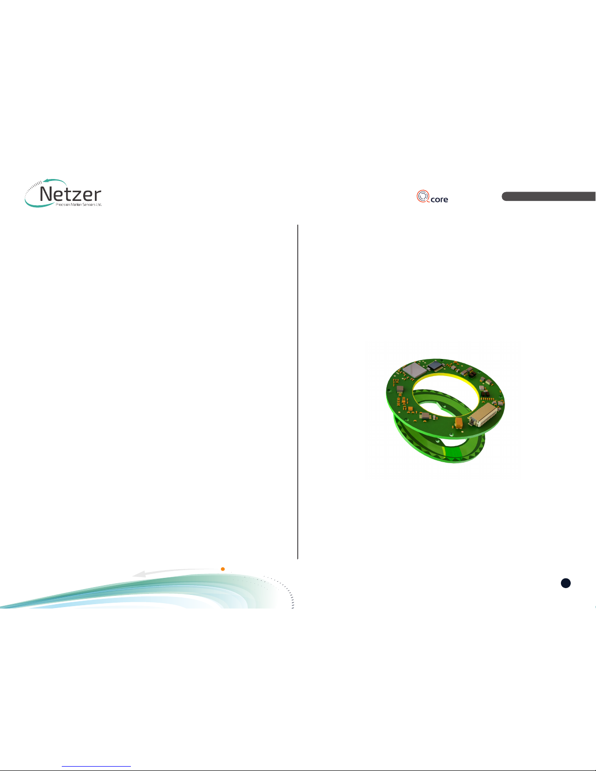
The VLX-60 Electric Encoder™ is semi-modular, i.e., its rotor
and stator are separate, with the stator securely housing the
rotor.
(1) Encoder stator
(2) Encoder rotor
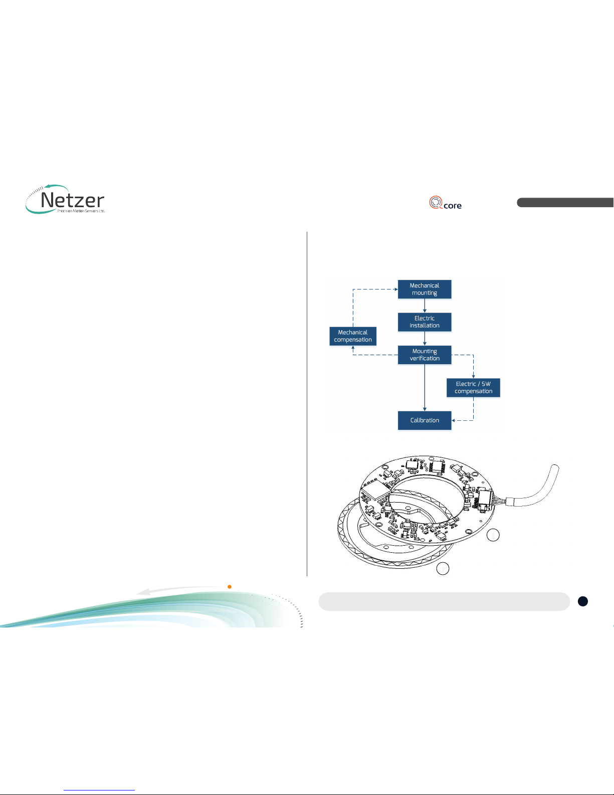
3.2 Installation flow chart
1
2
User Manual
Absolute Position Rotary Electric Encoder™|VLX-60
VLX-60 | July 2018 | Ver. 02
Corporate Headquarters
Netzer Precision Motion Sensors Ltd. | Misgav Industrial Park, P.O. Box 1359 | D.N. Misgav, 2017400 Israel
Tel : +972 4 999 0420 | global-info@netzerprecision.com | www.netzerprecision.com
Moving. Precisely. With You.
3
Contents |Preface |Safety |Product Overview |Unpacking |Electrical Connection
Software Installation |Mounting Verification |Calibration |Mechanical ICD |Mounting options
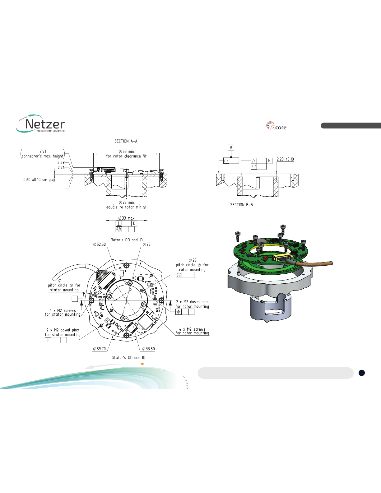
Typical encoder installation includes:
•Encoder Stator & Rotor mounting screws (3)
Socket Head Cup Screw 8 x M2
•Encoder Stator & Rotor mounting dowel pins
(4) , 4 x M2
3.3 Encoder Mounting
3
4
4
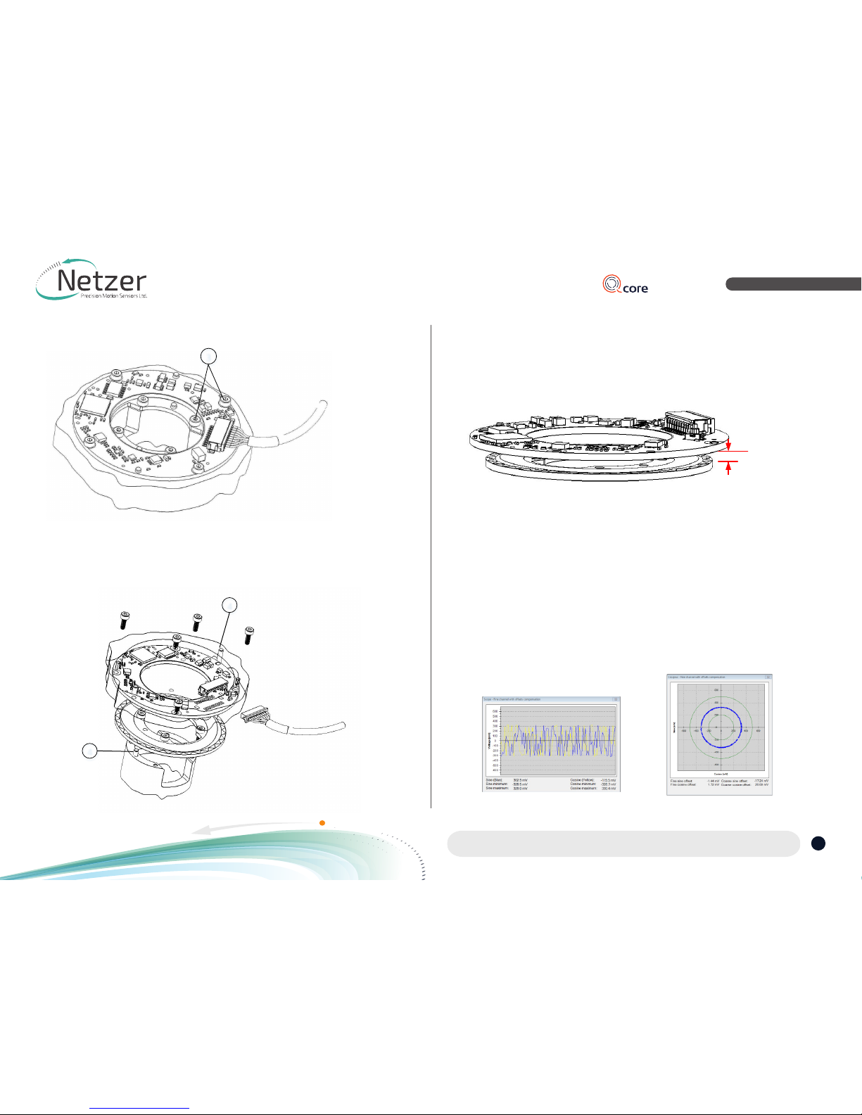
Encoder Stator / Rotor relative position
For proper performance the air gap should
be 0.6 mm +/- 0.1mm.
0.6 mm
Proper rotor mounting can be verified by
using the Encoder Explorer tools “signal
analyzer” or “Mechanical installation
verification”
Proper mounting will ensure correct
amplitude level of:
Fine channel 200 - 500mV
Coarse channel 200 - 500mV
User Manual
Absolute Position Rotary Electric Encoder™|VLX-60
VLX-60 | July 2018 | Ver. 02
Corporate Headquarters
Netzer Precision Motion Sensors Ltd. | Misgav Industrial Park, P.O. Box 1359 | D.N. Misgav, 2017400 Israel
Tel : +972 4 999 0420 | global-info@netzerprecision.com | www.netzerprecision.com
Moving. Precisely. With You.
4
Contents |Preface |Safety |Product Overview |Unpacking |Electrical Connection
Software Installation |Mounting Verification |Calibration |Mechanical ICD |Mounting options
4. Unpacking
4.1 Standard Order
The package of the standard VLX-60
contains the encoder Stator & Rotor.
Optional Accessories:
(1) Cables CB-00088-250 & CB-00088-500
(2) CNV-0003, RS-422 to USB converter
(with USB internal 5V power supply path)
5. Electrical interconnection
This chapter reviews the steps required to
electrically connect the VLX-60 with digital
interface (SSi or BiSS-C).
Connecting the Encoder
The VLX-60 operates has two operational
modes:
(i) i. Absolute Position over SSi or BiSS-C:
This is the power-up default mode.
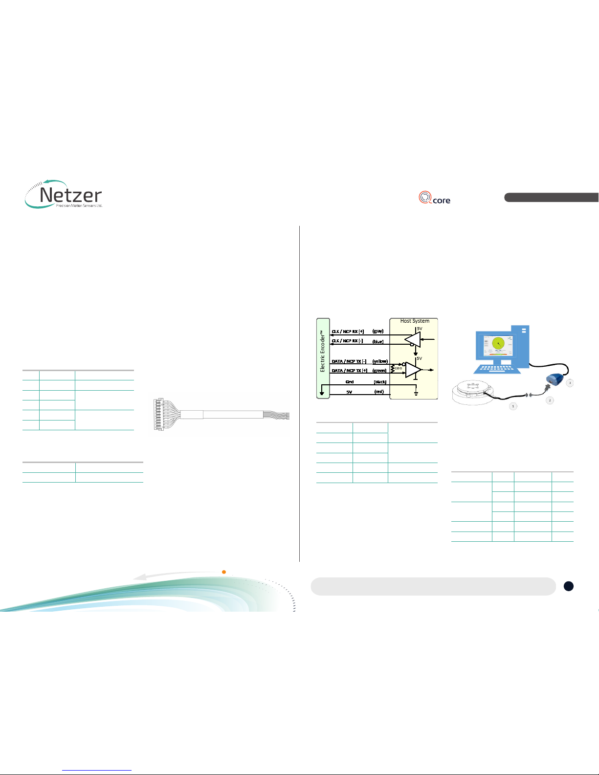
SSi / BiSS interface wires color code
Clock + Grey Clock
Clock - Blue
Data - Yellow Data
Data + Green
GND Black Ground
+5V Red Power supply
(ii) Configuration and setup mode:
This service mode provides access via
USB to a PC running Netzer Encoder
Explorer application (on MS Windows 7/8).
Communication is via Netzer Communication
Protocol (NCP) over RS-422 using the same
set of wires.
Use the following pin assignment to connect
the encoder to a 9-pin D-type connector to
the RS-422/USB converter CNV-0003.
Electric Encoder interface,
D Type 9 pin Female
Description Color Function Pin No
SSi Clock /
NCP RX
Gray Clock / RX + 2
Blue Clock / RX - 1
SSi Data /
NCP TX
Yellow Data / TX - 4
Green Data / TX + 3
Ground Black GND 5
Power supply Red +5V 8
(1) DF-60 encoder with SSi / BiSS interface.
(2/3) RS-422 / USB converter
(CAT No. CNV-00003)
Interconection - connector HRS DF13-10S-1.25
# SSi / BiSS Remarks
8 5V P.S.
7 GND GND /RTN
6 Data+ Data / NCP TX
5 Data-
4 Clock- Clock / NCP RX
3 Clock+ 1 -
SSi / BiSS Remarks
CB-00088-250 AWG30, 250 mm
CB-00088-500 AWG30, 500 mm
Accessories - cables, optional
User Manual
Absolute Position Rotary Electric Encoder™|VLX-60
VLX-60 | July 2018 | Ver. 02
Corporate Headquarters
Netzer Precision Motion Sensors Ltd. | Misgav Industrial Park, P.O. Box 1359 | D.N. Misgav, 2017400 Israel
Tel : +972 4 999 0420 | global-info@netzerprecision.com | www.netzerprecision.com
Moving. Precisely. With You.
5
Contents |Preface |Safety |Product Overview |Unpacking |Electrical Connection
Software Installation |Mounting Verification |Calibration |Mechanical ICD |Mounting options
6. Software Installation
The Electric Encoder Explorer (EEE)
software:
•Verifies Mechanical Mounting
Correctness
•Offsets Calibration
•Sets up general and signal analysis
This chapter reviews the steps associated
with installing the EEE software application.
6.1 Minimum Requirements
•Operating system: MS windows 7 , 32 /
64 bit
•Memory: 4MB minimum
•Communication ports: USB 2
•Windows .NET Framework , V4 minimum
6.2 Installing the Software
Run the Electric Encoder™ Explorer file
found on our website:
Encoder Explorer Sw Tools.
5.3 Electrical connection and grounding
The VLX-60 does NOT come with specified
cable and connector, however, do observe
grounding consideration:
(1) The cable shield does not connect to the
power supply return line.
(2)
Ground the host shaft to avoid
interference from the host system, which
could result in encoder internal noise.
Note: 4.75 to 5.25 VDC power supply required
7. Mounting Verification
Perform mounting verification before
calibration to ensure optimal performance
by selecting [Verification] on the main
screen of the Encoder Explorer or by using
the signal analyzer under “Tools.”
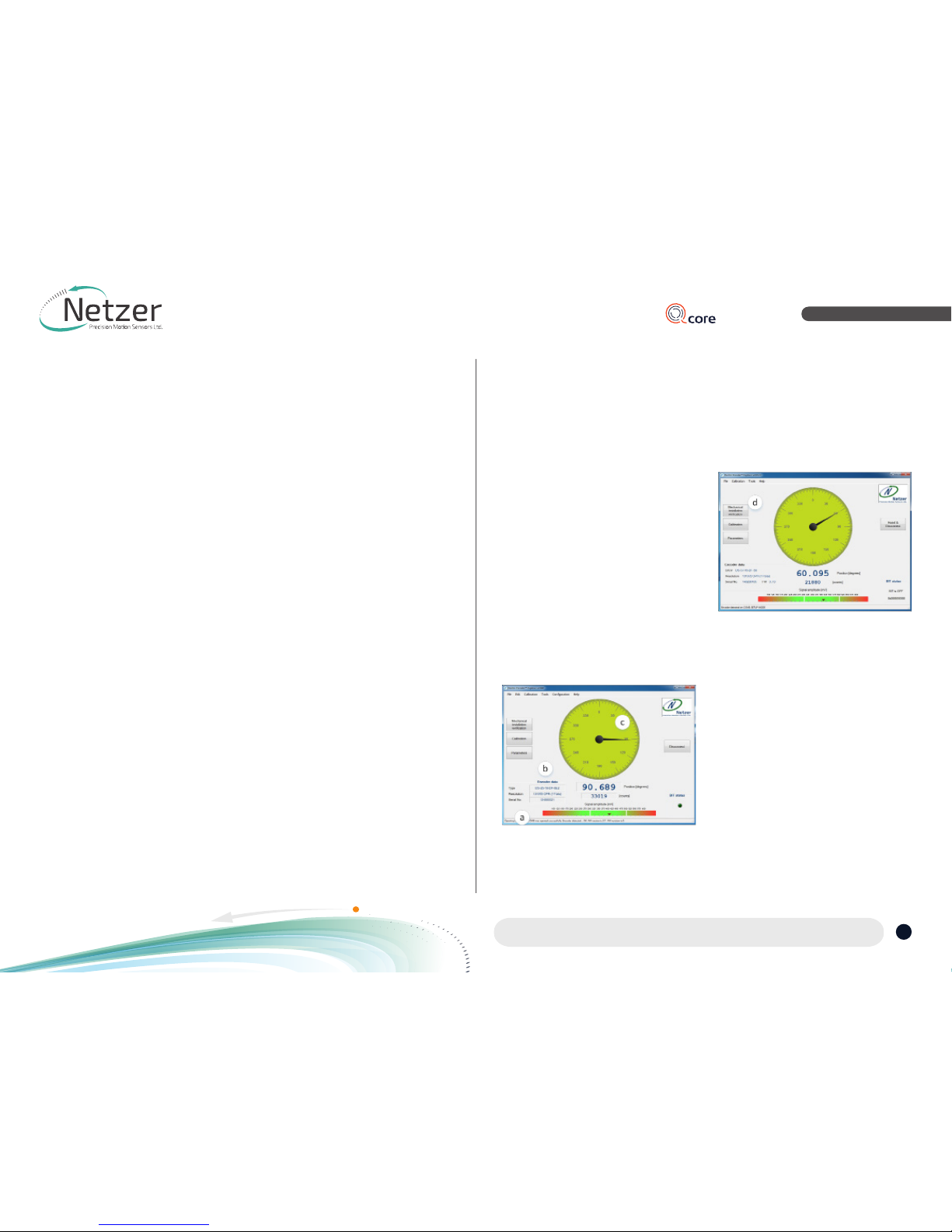
7.1 Starting the Encoder Explorer
Make sure to complete the following tasks
successfully:
•Mechanical Mounting
•Electrical Connection
•Connecting Encoder for Calibration
•Encoder Explore Software Installation
•Run the Electric Encoder Explorer tool
(EEE).
Ensure proper communication with the
encoder:
(a) The status bar indicates successful
communication.
(b) Encoder data displays in the Encoder
data area. (CAT No., serial No.)
(c) The position dial display responds to
shaft rotation.
7.2 Mechanical Installation Verification
The Mechanical Installation Verification
provides procedures to ensure proper
mechanical mounting by collecting raw
data of the coarse and fine channels during
rotation.
(d) Select [Mechanical Mounting Verification]
on the main screen.

User Manual
Absolute Position Rotary Electric Encoder™|VLX-60
VLX-60 | July 2018 | Ver. 02
Corporate Headquarters
Netzer Precision Motion Sensors Ltd. | Misgav Industrial Park, P.O. Box 1359 | D.N. Misgav, 2017400 Israel
Tel : +972 4 999 0420 | global-info@netzerprecision.com | www.netzerprecision.com
Moving. Precisely. With You.
6
Contents |Preface |Safety |Product Overview |Unpacking |Electrical Connection
Software Installation |Mounting Verification |Calibration |Mechanical ICD |Mounting options
(e) Select [Start] to initiate the data
collection.
(f) Rotate the shaft for data collecting of
the fine/coarse channels.
(g) At the end of successful verification, SW
shows “Correct Mechanical Installation.
(h) If SW indicates “Incorrect Mechanical
Installation,” place the mechanical
shims below the rotor, as presented in
paragraph 3.3 - “Rotor Relative Position.”
(i) Tools --> Signal analyzer , amplitude fine
tuning option with the UP / DOWN keys to the
nominal amplitude level , save the level by the
“set” option. This process available for the fine /
coarse and medium channels.
In case the reading data (blue dots) are not
evenly distributed on a thin circle, you may
experience “noise” in your installation (check
shaft/stator grounding).

User Manual
Absolute Position Rotary Electric Encoder™|VLX-60
VLX-60 | July 2018 | Ver. 02
Corporate Headquarters
Netzer Precision Motion Sensors Ltd. | Misgav Industrial Park, P.O. Box 1359 | D.N. Misgav, 2017400 Israel
Tel : +972 4 999 0420 | global-info@netzerprecision.com | www.netzerprecision.com
Moving. Precisely. With You.
7
Contents |Preface |Safety |Product Overview |Unpacking |Electrical Connection
Software Installation |Mounting Verification |Calibration |Mechanical ICD |Mounting options
8. Calibration
8.1 Offset Calibration
For optimal performance of the VLX-60
Electric Encoder, the inevitable DC offset
of the sine and cosine signals must be
compensated over the operational sector.
After successfully completing the Mounting
Verification procedure:
(a) Select [Calibration] on the main screen.
(b) Start the data acquisition while rotating
the shaft.
The progress bar (c) indicates the collection
progress.
Rotate the axis consistently during data
collection—covering the working sector
of the application end to end—by default
the procedure collects 500 points over 75
seconds. Rotation speed is not a parameter
during data collection. Data collection
indication shows for the fine/coarse
channels, a clear “thin” circle appears in the
center (d) (e) with some offset.
8.2 CAA Calibration
The following calibration aligns the coarse/
fine channel by collecting data from each
point of both channels.
Select [Continue to CAA Calibration]
In the CAA angle calibration window,
select the relevant option button from the
measurement range options (a):
•Full mechanical rotation – shaft
movement is over 10deg -
recommended.
•Limited section – define operation of
the shaft in a limited angle defined by
degrees in case of <10deg
•
Free sampling modes - define the number
of calibration points in the total number
of points in the text box. The system
displays the recommended number of
points by default. Collect a minimum of
nine points over the working sector.
•Click the [Start Calibration] button (b)
•The status (c) indicates the next required
operation; the shaft movement status;
the current position, and the next target
position to which the encoder should be
rotated.
•Rotate the shaft/encoder to the next
position and click the [Continue] button
(c) - the shaft should be in STAND STILL
during the data collection. Follow the
indication/interactions during the cyclic
process for positioning the shaft -->
stand still --> reading calculation.
•Repeat the above step for all defined
points. Finish (d)
•Click the [Save and Continue] button (e).
The last step saves the offsets CAA
parameters, completing the calibration
process.

User Manual
Absolute Position Rotary Electric Encoder™|VLX-60
VLX-60 | July 2018 | Ver. 02
Corporate Headquarters
Netzer Precision Motion Sensors Ltd. | Misgav Industrial Park, P.O. Box 1359 | D.N. Misgav, 2017400 Israel
Tel : +972 4 999 0420 | global-info@netzerprecision.com | www.netzerprecision.com
Moving. Precisely. With You.
8
Contents |Preface |Safety |Product Overview |Unpacking |Electrical Connection
Software Installation |Mounting Verification |Calibration |Mechanical ICD |Mounting options
8.3 Setting the Encoder Zero Point
•The zero position can be defined
anywhere in the working sector.
•Rotate the shaft to the desired zero
mechanical position.
•Select “Set Current Position” as zero
by using the relevant option, and click
[Finish].
8.4 Jitter test
Perform a jitter test to evaluate the quality
of the installation; the jitter test presents
the reading statistics of absolute position
readings (counts) over time. Common jitter
should be up +/- three counts; higher jitter
may indicate system noise.
8.5 Automatic calibration
The VLX-60 includes “on board” automatic
calibration option, eliminate the need for
external SW tools. CALL for support.
User Manual
Absolute Position Rotary Electric Encoder™|VLX-60
VLX-60 | July 2018 | Ver. 02
Corporate Headquarters
Netzer Precision Motion Sensors Ltd. | Misgav Industrial Park, P.O. Box 1359 | D.N. Misgav, 2017400 Israel
Tel : +972 4 999 0420 | global-info@netzerprecision.com | www.netzerprecision.com
Moving. Precisely. With You.
9
Contents |Preface |Safety |Product Overview |Unpacking |Electrical Connection
Software Installation |Mounting Verification |Calibration |Mechanical ICD |Mounting options
56.50
16
AA
0.1
A
0.1
A
0.05
A
A
0
1.60
0.05
0.1
A
0.05 0.05
0.05
UNLESS OTHERWISE SPECIFIED
Dimentions are in: mm
Surface Finish: N6
Linear Tolerances: ±0.5 deg
All Chamfer: 0.1 mm x 45°
Other manuals for VLX-60
1
Table of contents
Other Netzer Media Converter manuals


